US9869963B2 - Image forming apparatus with opening and closing member and reaction force generating mechanism - Google Patents
Image forming apparatus with opening and closing member and reaction force generating mechanism Download PDFInfo
- Publication number
- US9869963B2 US9869963B2 US15/246,831 US201615246831A US9869963B2 US 9869963 B2 US9869963 B2 US 9869963B2 US 201615246831 A US201615246831 A US 201615246831A US 9869963 B2 US9869963 B2 US 9869963B2
- Authority
- US
- United States
- Prior art keywords
- opening
- closing member
- reaction force
- main body
- image forming
- Prior art date
- Legal status (The legal status is an assumption and is not a legal conclusion. Google has not performed a legal analysis and makes no representation as to the accuracy of the status listed.)
- Active
Links
Images


Classifications
-
- G—PHYSICS
- G03—PHOTOGRAPHY; CINEMATOGRAPHY; ANALOGOUS TECHNIQUES USING WAVES OTHER THAN OPTICAL WAVES; ELECTROGRAPHY; HOLOGRAPHY
- G03G—ELECTROGRAPHY; ELECTROPHOTOGRAPHY; MAGNETOGRAPHY
- G03G21/00—Arrangements not provided for by groups G03G13/00 - G03G19/00, e.g. cleaning, elimination of residual charge
- G03G21/16—Mechanical means for facilitating the maintenance of the apparatus, e.g. modular arrangements
- G03G21/1604—Arrangement or disposition of the entire apparatus
- G03G21/1623—Means to access the interior of the apparatus
- G03G21/1633—Means to access the interior of the apparatus using doors or covers
-
- G—PHYSICS
- G03—PHOTOGRAPHY; CINEMATOGRAPHY; ANALOGOUS TECHNIQUES USING WAVES OTHER THAN OPTICAL WAVES; ELECTROGRAPHY; HOLOGRAPHY
- G03G—ELECTROGRAPHY; ELECTROPHOTOGRAPHY; MAGNETOGRAPHY
- G03G2215/00—Apparatus for electrophotographic processes
- G03G2215/01—Apparatus for electrophotographic processes for producing multicoloured copies
- G03G2215/0103—Plural electrographic recording members
- G03G2215/0119—Linear arrangement adjacent plural transfer points
- G03G2215/0122—Linear arrangement adjacent plural transfer points primary transfer to an intermediate transfer belt
- G03G2215/0125—Linear arrangement adjacent plural transfer points primary transfer to an intermediate transfer belt the linear arrangement being horizontal or slanted
- G03G2215/0132—Linear arrangement adjacent plural transfer points primary transfer to an intermediate transfer belt the linear arrangement being horizontal or slanted vertical medium transport path at the secondary transfer
Definitions
- the present invention relates to an image forming apparatus.
- an image forming apparatus including:
- FIG. 1 is a cross-sectional schematic diagram illustrating a construction of an inner portion of an image forming apparatus
- FIG. 2 is a perspective view illustrating the inner surface side of a rear cover of the image forming apparatus
- FIG. 3 is a cross-sectional schematic diagram of a main portion illustrating a state where the rear cover of the image forming apparatus is engaged to a main body of the apparatus at a closing position;
- FIG. 4 is a cross-sectional schematic diagram of a main portion illustrating a state where a rear cover is engaged to a main body of the apparatus at a closing position;
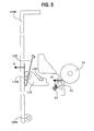
- FIG. 5 is a cross-sectional schematic diagram of a main portion illustrating a state where a rear cover is engaged to a main body of the apparatus at a closing position;
- FIG. 6 is a cross-sectional schematic diagram illustrating a force acting on an engaging member when a rear cover of a comparative example moves from an opening position to a closing position;
- FIG. 7 is a view illustrating a relationship between a drawing force and an internal reaction force acting when the rear cover of the comparative example moves from the opening position to the closing position;
- FIG. 8 is a view illustrating a relationship between a drawing force and an internal reaction force acting when the rear cover moves from the opening position to the closing position.
- the longitudinal direction is referred to as the X-axis direction
- the lateral direction is referred to as the Y-axis direction
- the vertical direction is referred to as the Z-axis direction.
- FIG. 1 is a longitudinal cross-sectional schematic diagram illustrating a construction of an inner portion of an image forming apparatus 1 according to an exemplary embodiment.
- the image forming apparatus 1 includes a control device 10 , a sheet feeding device 20 , a photoconductor unit 30 , a developing device 40 , an exposure device 50 , a transfer device 60 , and a fixing device 70 .
- An upper cover 80 that also serves as an exit tray to which the image recorded paper is discharged or in which the image recorded paper is received is provided to the upper surface (the Z direction) of the image forming apparatus 1 .
- a front cover 90 that allows the inner portion of the image forming apparatus 1 to be opened in the front direction (in the X direction) in a case of exchange of the consumables or the like is rotatably supported to the front surface of the image forming apparatus 1 .
- a rear cover 100 that allows the inner portion of the image forming apparatus 1 to be opened in the rear direction (in the ⁇ X direction) in a case of a paper jam, internal inspection, or the like is rotatably supported to the rear surface of the image forming apparatus 1 .
- the control device 10 includes a controller 11 of the image forming apparatus that controls an operation of the image forming apparatus 1 , a controller unit 12 that prepares image data according to a print processing request, an exposure controller 13 that controls the lighting of the light source of the exposure device 50 , a power supply device 14 , or the like.
- the power supply device 14 applies voltage to a charging roller 32 , a developing roller 42 , a transfer roller 62 , or the like, which are described below and supplies power to the exposure device 50 .
- the controller unit 12 converts image data which is input from an image reading apparatus (not illustrated) or print information which is input from an external information transmission apparatus (for example, a personal computer or the like) into image information for forming a latent image and then outputs a drive signal to the exposure controller 13 at the preset timing.
- the sheet feeding device 20 is provided in the bottom portion of the image forming apparatus 1 .
- the sheet feeding device 20 includes a paper cassette 21 . Paper P as plural recording mediums is stacked on the upper surface of the paper cassette 21 .
- the paper P of which the position in the width direction is determined by a regulation plate (not illustrated) is withdrawn one by one from the upper side in the rear direction (in the ⁇ X direction) by a paper withdrawal unit 22 and is transported to a contact portion of a pair of resist rollers 23 .
- the photoconductor unit 30 is provided at the upper side of the sheet feeding device 20 , and includes a photoconductor drum 31 which rotates to drive in the inside of a unit housing 35 .
- the charging roller 32 , the developing device 40 , the transfer roller 62 , and a cleaning blade 34 are disposed along the rotating direction of the photoconductor drum 31 .
- a cleaning roller 33 which cleans the surface of the charging roller 32 is disposed to face and be in contact with the charging roller 32 .
- the developing device 40 includes a developing housing 41 of which a developer is contained in the inner portion.
- a developing roller 42 which is disposed to face the photoconductor drum 31 and a pair of augers 44 and 45 which agitates and transports the developer to the developing roller 42 and is on the inclined lower side of the rear surface side of the developing roller 42 are provided in the developing housing 41 .
- a layer regulation roller 46 which regulates a layer thickness of the developer is disposed to be close to the developing roller 42 .
- the exposure device 50 includes a light emitting diode (LED) head in which plural LEDs are disposed in a linear shape along a main scanning direction and exposes the surface of the photoconductor drum 31 with a modulated light according to data of an image to be formed.
- LED light emitting diode
- the exposure device 50 moves with respect to the main body of the apparatus between a light exposing position at which the photoconductor drum 31 is exposed with light and a retracted position which is separated from the photoconductor drum 31 , in a state of being held in a holding member 51 by the opening and closing operation of the front cover 90 .
- the surface of the rotating photoconductor drum 31 is charged by the charging roller 32 and an electrostatic latent image is formed by the exposure device 50 .
- the electrostatic latent image formed on the photoconductor drum 31 is developed as a toner image by the developing roller 42 .
- the transfer device 60 includes the rear cover 100 which seperatably supports the transfer roller 62 to the photoconductor drum 31 and the transfer roller 62 which forms a nip with the photoconductor drum 31 .
- a transfer voltage from the power supply device 14 which is controlled by the controller 11 of the image forming apparatus is applied to the transfer roller 62 and the toner image on the photoconductor drum 31 is transferred on the paper P which passes through between the photoconductor drum 31 and the transfer roller 62 .
- a residual toner on the surface of the photoconductor drum 31 is removed by the cleaning blade 34 and is collected in the inside of the unit housing 35 which supports the photoconductor drum 31 . Subsequently, the surface of the photoconductor drum 31 is charged again by the charging roller 32 . Furthermore, the residue which is not removed by the cleaning blade 34 and thus is attached to the charging roller 32 is captured on the surface of the cleaning roller 33 which rotates while being in contact with the charging roller 32 and thus is temporarily stored in the charging roller 32 .
- the fixing device 70 includes a pair of heating module 71 and a pressuring module 72 .
- a fixing nip portion (fixing region) is formed by a pressure contact region of the heating module 71 and the pressuring module 72 .
- the paper P on which the toner image is transferred by the transfer roller 62 is transported to the fixing device 70 via a transport guide 64 in a state where the toner image is unfixed.
- the toner image is fixed to the paper P which is transported to the fixing device 70 by press contact and heating by the pair of the heating module 71 and the pressuring module 72 .
- the paper P on which the fixed toner image is formed is discharged from a pair of discharging rollers 74 to the upper cover 1 c of the upper surface of the image forming apparatus 1 .
- FIG. 2 is a perspective view illustrating the inner surface side of the rear cover 100 of the image forming apparatus 1
- FIG. 3 is a cross-sectional schematic diagram of a main portion illustrating a state where the rear cover 100 of the image forming apparatus 1 is engaged with the main body of the apparatus at the closing position.
- the rear cover 100 as an example of the opening and closing member which is rotatably supported to the left side of the image forming apparatus 1 is movably supported between an opening position at which the inner portion of the main body of the apparatus is opened and a closing position at which the inner portion of the main body of the apparatus is closed.
- a rotating shaft 100 a is formed on the lower end portion of the rear cover 100 , and the rear cover 100 is rotatably supported to the main body of the apparatus by the rotating shaft 100 a.
- a torsion spring 101 as an example of a reaction force generating mechanism is held to be wound in the rotating shaft 100 a so that one end of the torsion spring is fixed to the main body of the apparatus and the other end thereof is in contact with the inner surface of the rear cover 100 .
- a reaction force which urges toward the opening position acts on the rear cover 100 when the rear cover 100 moves from the opening position to the closing position.
- An engaging member 110 includes a guiding surface 111 which guides the engaging member 110 to the engaging position while being in contact with the engaging shaft 120 provided in the main body of the apparatus and a concave engaging portion 112 into which the engaging shaft 120 is fitted.
- the engaging member 110 is rotatably supported to the both sides in the lateral direction (in the Y direction, ⁇ Y direction) of the rear cover 100 while being urged in the rotating direction by the torsion spring (not illustrated) at the rotation center 110 a.
- the pair of resist rollers 23 which transports the paper P sent from the sheet feeding device 20 while aligning the paper P, the photoconductor unit 30 , and the fixing device 70 are disposed on the main body side of the apparatus of which the rear cover 100 is opened.
- the transfer roller 62 and the transport guide 64 which guides the paper P on which the toner image is transferred from the transfer roller 62 to the fixing device 70 are provided on the inner surface side of the rear cover 100 .
- the engaging member 110 is rotatably supported to the both sides of the rear cover 100 in the lateral direction, and the engaging member 110 is fitted into the engaging shaft 120 (illustrated in FIG. 3 ) as an engaged member provided in the main body of the apparatus and thus the left side of the main body of the apparatus becomes a closed state.
- FIG. 6 is a cross-sectional schematic diagram illustrating a force acting on the engaging member 110 when a rear cover 200 of a comparative example moves from the opening position to the closing position
- FIG. 7 is a view illustrating a relationship between a drawing force and an internal reaction force acting when the rear cover 200 of the comparative example moves from the opening position to the closing position
- FIG. 8 is a view illustrating a relationship between a drawing force and an internal reaction force acting when the rear cover 100 moves from the opening position to the closing position.
- the rear cover 200 of the comparative example includes a guiding surface 111 which guides the engaging member 110 to the engaging position while being in contact with the engaging shaft 120 provided in the main body of the apparatus, and a concave engaging portion 112 into which the engaging shaft 120 is fitted.
- the rear cover 200 includes the engaging member 110 which is rotatably supported while being urged in the rotating direction by the torsion spring (not illustrated) at the rotation center 110 a.
- the engaging shaft 120 is disengaged from the end portion of the guiding surface 111 and then is fitted into the concave engaging portion 112 (see dashed lines in FIG. 6 ).
- the rear cover 200 in the closing operation of the related rear cover 200 , a position at which the drawing force F2 based on the engaging force F1 and the internal reaction force (f1) are balanced is generated, and in a case where the closing operation of the rear cover 200 is stopped at the balanced position related and thus the rotation of the engaging member 110 is stopped, the rear cover 200 is substantially positioned at the closing position (an irregular position), since the concave engaging portion 112 of the engaging member 110 is started to be fitted into the engaging shaft 120 of the main body of the apparatus.
- the torsion spring 101 as an example of the reaction force generating mechanism is held to be wound around the rotating shaft 100 a so that one end of the torsion spring 101 is fixed to the main body of the apparatus and the other end thereof is in contact with the inner surface of the rear cover 100 .
- reaction force (f2) which urges toward the opening position acts on the rear cover 100 when the rear cover 100 moves from the opening position to the closing position.
- the internal reaction force (f1+f2) is normally greater than the drawing force F2 based on the engaging force F1 and is not balanced with the drawing force, in a case where the closing operation of the rear cover 100 is stopped and thus the rotation of the engaging member 110 is stopped, an urging force toward the opening position normally acts on the rear cover 100 , and thus the rear cover 100 is not stopped at an irregular position.
- FIG. 4 is a cross-sectional schematic diagram of a main portion illustrating a state where the rear cover 100 A according to the exemplary embodiment is engaged to the main body of the apparatus at the closing position.
- the rear cover 100 A includes a plunger 102 , as an example of the reaction force generating mechanism, which is movably supported to the moving direction of the rear cover 100 A in the rear cover 100 A and is pressed by the movement of the rear cover 100 A from the opening position to the closing position.
- a plunger 102 as an example of the reaction force generating mechanism
- the plunger 102 is provided at the center portion of the rear cover 100 A so that a front end side thereof protrudes in the moving direction of the rear cover 100 A toward the closing direction via a coil spring 104 in the case body 103 . Then, in a case where the closing operation is performed with respect to the rear cover 100 A, the front end portion of the plunger 102 is in contact with the main body of the apparatus, and the reaction force (f1+f2) to which the reaction force (f2) due to the coil spring 104 urging the plunger 102 is added acts on the rear cover 100 A.
- the internal reaction force (f1+f2) is normally greater than the drawing force F2 based on the engaging force F1
- an urging force toward the opening position normally acts on the rear cover 100 A, and thus the rear cover 100 A is not stopped at an irregular position.
- FIG. 5 is a cross-sectional schematic diagram of a main portion illustrating a state where a rear cover 100 B according to the exemplary embodiment is engaged to the main body of the apparatus at the closing position.
- the rear cover 100 B includes a leaf spring 105 , as an example of the reaction force generating mechanism, which is disposed on an inner surface of the rear cover 100 B and is pressed to be deformed by the movement of the rear cover 100 B from the opening position to the closing position.
- the front end portion of the leaf spring 105 is in contact with the main body of the apparatus, and the reaction force (f1+f2) to which the reaction force (f2) due to the leaf spring 105 is added acts on the rear cover 100 B.
- the internal reaction force (f1+f2) is normally greater than the drawing force F2 based on the engaging force F1
- an urging force toward the opening position normally acts on the rear cover 100 B, and thus the rear cover 100 B is not stopped at an irregular position.
Landscapes
- Physics & Mathematics (AREA)
- General Physics & Mathematics (AREA)
- Electrophotography Configuration And Component (AREA)
Abstract
Description
-
- an opening and closing member that is movably supported between an opening position at which an inner portion of a main body of the apparatus is opened and a closing position at which the inner portion of the main body of the apparatus is closed;
- an engaged portion that is provided in the main body of the apparatus;
- an engaging member that is provided in the opening and closing member and is engaged to the engaged portion; and
- a reaction force generating mechanism that is provided in the opening and closing member, and urges the opening and closing member toward the opening position when the opening and closing member moves from the opening position to the closing position.
Claims (7)
Applications Claiming Priority (2)
| Application Number | Priority Date | Filing Date | Title |
|---|---|---|---|
| JP2016036536A JP6699233B2 (en) | 2016-02-29 | 2016-02-29 | Image forming device |
| JP2016-036536 | 2016-02-29 |
Publications (2)
| Publication Number | Publication Date |
|---|---|
| US20170248901A1 US20170248901A1 (en) | 2017-08-31 |
| US9869963B2 true US9869963B2 (en) | 2018-01-16 |
Family
ID=59679514
Family Applications (1)
| Application Number | Title | Priority Date | Filing Date |
|---|---|---|---|
| US15/246,831 Active US9869963B2 (en) | 2016-02-29 | 2016-08-25 | Image forming apparatus with opening and closing member and reaction force generating mechanism |
Country Status (2)
| Country | Link |
|---|---|
| US (1) | US9869963B2 (en) |
| JP (1) | JP6699233B2 (en) |
Families Citing this family (3)
| Publication number | Priority date | Publication date | Assignee | Title |
|---|---|---|---|---|
| JP6882872B2 (en) * | 2016-09-21 | 2021-06-02 | 株式会社東芝 | Image forming device |
| JP7040438B2 (en) * | 2018-12-28 | 2022-03-23 | 沖電気工業株式会社 | Image forming device |
| US12158719B2 (en) * | 2022-06-13 | 2024-12-03 | Ricoh Company, Ltd. | Sheet laminator and image forming system incorporating the sheet laminator |
Citations (9)
| Publication number | Priority date | Publication date | Assignee | Title |
|---|---|---|---|---|
| US5999772A (en) * | 1997-09-08 | 1999-12-07 | Ricoh Company, Ltd. | Image forming apparatus with support member |
| US20070091387A1 (en) * | 2005-10-26 | 2007-04-26 | Masayuki Kakuta | Switching device |
| US20080175620A1 (en) * | 2007-01-24 | 2008-07-24 | Ricoh Company, Ltd. | Upper frame opening and closing mechanism, and image forming apparatus using the same |
| US20100239311A1 (en) * | 2009-03-23 | 2010-09-23 | Canon Kabushiki Kaisha | Electrophotographic image forming apparatus |
| US20100247142A1 (en) * | 2009-03-23 | 2010-09-30 | Canon Kabushiki Kaisha | Color electrophotographic image forming apparatus |
| JP2011127383A (en) | 2009-12-21 | 2011-06-30 | Mitsui Kinzoku Act Corp | Actuator for vehicle door latch device |
| JP2011127420A (en) | 2009-11-19 | 2011-06-30 | Aisin Kiko Co Ltd | Door latch device |
| US20120027422A1 (en) * | 2010-08-02 | 2012-02-02 | Brother Kogyo Kabushiki Kaisha | Image Forming Device Capable of Preventing Foreign Matters From Entering Developing Unit |
| US20150042108A1 (en) | 2013-08-07 | 2015-02-12 | Mitsui Kinzoku Act Coporation | Motor-vehicle door latch device |
Family Cites Families (9)
| Publication number | Priority date | Publication date | Assignee | Title |
|---|---|---|---|---|
| JP3366295B2 (en) * | 1998-10-12 | 2003-01-14 | コピア株式会社 | Image forming device |
| JP2003218550A (en) * | 2002-01-28 | 2003-07-31 | Mitsubishi Electric Corp | Door opening and closing mechanism |
| JP2006137110A (en) * | 2004-11-12 | 2006-06-01 | Canon Inc | Case opening / closing mechanism and image forming apparatus |
| JP2009300930A (en) * | 2008-06-17 | 2009-12-24 | Fuji Xerox Co Ltd | Image forming apparatus |
| JP5533401B2 (en) * | 2010-07-29 | 2014-06-25 | ブラザー工業株式会社 | Image forming apparatus |
| CN202230300U (en) * | 2011-09-26 | 2012-05-23 | 珠海赛纳打印科技股份有限公司 | Image forming device |
| EP2587314B1 (en) * | 2011-10-26 | 2020-09-23 | Hewlett-Packard Development Company, L.P. | Image forming apparatus |
| JP6116202B2 (en) * | 2012-11-21 | 2017-04-19 | キヤノン株式会社 | Image forming apparatus |
| JP6122791B2 (en) * | 2014-01-31 | 2017-04-26 | 京セラドキュメントソリューションズ株式会社 | Image forming apparatus |
-
2016
- 2016-02-29 JP JP2016036536A patent/JP6699233B2/en active Active
- 2016-08-25 US US15/246,831 patent/US9869963B2/en active Active
Patent Citations (11)
| Publication number | Priority date | Publication date | Assignee | Title |
|---|---|---|---|---|
| US5999772A (en) * | 1997-09-08 | 1999-12-07 | Ricoh Company, Ltd. | Image forming apparatus with support member |
| US20070091387A1 (en) * | 2005-10-26 | 2007-04-26 | Masayuki Kakuta | Switching device |
| US20080175620A1 (en) * | 2007-01-24 | 2008-07-24 | Ricoh Company, Ltd. | Upper frame opening and closing mechanism, and image forming apparatus using the same |
| US20100239311A1 (en) * | 2009-03-23 | 2010-09-23 | Canon Kabushiki Kaisha | Electrophotographic image forming apparatus |
| US20100247142A1 (en) * | 2009-03-23 | 2010-09-30 | Canon Kabushiki Kaisha | Color electrophotographic image forming apparatus |
| JP2011127420A (en) | 2009-11-19 | 2011-06-30 | Aisin Kiko Co Ltd | Door latch device |
| JP2011127383A (en) | 2009-12-21 | 2011-06-30 | Mitsui Kinzoku Act Corp | Actuator for vehicle door latch device |
| US20120256429A1 (en) | 2009-12-21 | 2012-10-11 | Nagaoka Tomoharu | Actuator in a vehicle door latch device |
| US20120027422A1 (en) * | 2010-08-02 | 2012-02-02 | Brother Kogyo Kabushiki Kaisha | Image Forming Device Capable of Preventing Foreign Matters From Entering Developing Unit |
| US20150042108A1 (en) | 2013-08-07 | 2015-02-12 | Mitsui Kinzoku Act Coporation | Motor-vehicle door latch device |
| JP2015031132A (en) | 2013-08-07 | 2015-02-16 | 三井金属アクト株式会社 | Door latch device for automobile |
Also Published As
| Publication number | Publication date |
|---|---|
| US20170248901A1 (en) | 2017-08-31 |
| JP6699233B2 (en) | 2020-05-27 |
| JP2017156360A (en) | 2017-09-07 |
Similar Documents
| Publication | Publication Date | Title |
|---|---|---|
| US9284143B2 (en) | Sheet transport device, and image forming apparatus | |
| US7756441B2 (en) | Process cartridge and electrophotographic image forming apparatus | |
| CN103941559B (en) | Sheet material conveyor | |
| US9482983B1 (en) | Image forming apparatus with moveable exposure device | |
| JP6658096B2 (en) | Image forming device | |
| US9869963B2 (en) | Image forming apparatus with opening and closing member and reaction force generating mechanism | |
| US10481551B2 (en) | Image forming apparatus with pivotable transfer unit positioning portion | |
| US10114332B2 (en) | Opening-closing mechanism and image forming apparatus | |
| CN108780295B (en) | Image forming apparatus with a toner supply device | |
| US7987971B2 (en) | Belt device and fixing device | |
| JP4613538B2 (en) | Image forming apparatus | |
| US10603935B1 (en) | Opening and closing mechanism and image forming apparatus | |
| JP2006030418A (en) | Image forming apparatus | |
| US10725425B2 (en) | Image forming apparatus | |
| JP2016206333A (en) | Image forming apparatus | |
| CN105739276B (en) | image forming apparatus | |
| JP2008268401A (en) | Image fixing unit and image forming device incorporating it | |
| US9487368B1 (en) | Image forming apparatus with rotatable paper conveyance assembly | |
| JP5895608B2 (en) | Paper transport device and image forming apparatus | |
| JP6515717B2 (en) | Image forming device | |
| JP2003186269A (en) | Image forming device | |
| JP5958358B2 (en) | Image forming apparatus | |
| JP2006056657A (en) | Image forming apparatus | |
| JP2005208075A (en) | Image forming apparatus | |
| JP2006030647A (en) | Image forming apparatus |
Legal Events
| Date | Code | Title | Description |
|---|---|---|---|
| AS | Assignment |
Owner name: FUJI XEROX CO., LTD., JAPAN Free format text: ASSIGNMENT OF ASSIGNORS INTEREST;ASSIGNOR:UESHIMA, AKIRA;REEL/FRAME:039539/0419 Effective date: 20160727 |
|
| STCF | Information on status: patent grant |
Free format text: PATENTED CASE |
|
| MAFP | Maintenance fee payment |
Free format text: PAYMENT OF MAINTENANCE FEE, 4TH YEAR, LARGE ENTITY (ORIGINAL EVENT CODE: M1551); ENTITY STATUS OF PATENT OWNER: LARGE ENTITY Year of fee payment: 4 |
|
| AS | Assignment |
Owner name: FUJIFILM BUSINESS INNOVATION CORP., JAPAN Free format text: CHANGE OF NAME;ASSIGNOR:FUJI XEROX CO., LTD.;REEL/FRAME:058287/0056 Effective date: 20210401 |
|
| MAFP | Maintenance fee payment |
Free format text: PAYMENT OF MAINTENANCE FEE, 8TH YEAR, LARGE ENTITY (ORIGINAL EVENT CODE: M1552); ENTITY STATUS OF PATENT OWNER: LARGE ENTITY Year of fee payment: 8 |