US9868330B2 - Leaf spring assembly for motor vehicles - Google Patents
Leaf spring assembly for motor vehicles Download PDFInfo
- Publication number
- US9868330B2 US9868330B2 US14/905,840 US201414905840A US9868330B2 US 9868330 B2 US9868330 B2 US 9868330B2 US 201414905840 A US201414905840 A US 201414905840A US 9868330 B2 US9868330 B2 US 9868330B2
- Authority
- US
- United States
- Prior art keywords
- leaf spring
- spring
- end portion
- receiving device
- spring assembly
- Prior art date
- Legal status (The legal status is an assumption and is not a legal conclusion. Google has not performed a legal analysis and makes no representation as to the accuracy of the status listed.)
- Active
Links
Images


Classifications
-
- B—PERFORMING OPERATIONS; TRANSPORTING
- B60—VEHICLES IN GENERAL
- B60G—VEHICLE SUSPENSION ARRANGEMENTS
- B60G11/00—Resilient suspensions characterised by arrangement, location or kind of springs
- B60G11/02—Resilient suspensions characterised by arrangement, location or kind of springs having leaf springs only
- B60G11/04—Resilient suspensions characterised by arrangement, location or kind of springs having leaf springs only arranged substantially parallel to the longitudinal axis of the vehicle
-
- B—PERFORMING OPERATIONS; TRANSPORTING
- B60—VEHICLES IN GENERAL
- B60G—VEHICLE SUSPENSION ARRANGEMENTS
- B60G11/00—Resilient suspensions characterised by arrangement, location or kind of springs
- B60G11/02—Resilient suspensions characterised by arrangement, location or kind of springs having leaf springs only
- B60G11/10—Resilient suspensions characterised by arrangement, location or kind of springs having leaf springs only characterised by means specially adapted for attaching the spring to axle or sprung part of the vehicle
- B60G11/12—Links, pins, or bushes
-
- F—MECHANICAL ENGINEERING; LIGHTING; HEATING; WEAPONS; BLASTING
- F16—ENGINEERING ELEMENTS AND UNITS; GENERAL MEASURES FOR PRODUCING AND MAINTAINING EFFECTIVE FUNCTIONING OF MACHINES OR INSTALLATIONS; THERMAL INSULATION IN GENERAL
- F16F—SPRINGS; SHOCK-ABSORBERS; MEANS FOR DAMPING VIBRATION
- F16F1/00—Springs
- F16F1/36—Springs made of rubber or other material having high internal friction, e.g. thermoplastic elastomers
- F16F1/366—Springs made of rubber or other material having high internal friction, e.g. thermoplastic elastomers made of fibre-reinforced plastics, i.e. characterised by their special construction from such materials
- F16F1/368—Leaf springs
- F16F1/3683—Attachments or mountings therefor
- F16F1/3686—End mountings
-
- B—PERFORMING OPERATIONS; TRANSPORTING
- B60—VEHICLES IN GENERAL
- B60G—VEHICLE SUSPENSION ARRANGEMENTS
- B60G2202/00—Indexing codes relating to the type of spring, damper or actuator
- B60G2202/10—Type of spring
- B60G2202/11—Leaf spring
- B60G2202/112—Leaf spring longitudinally arranged
-
- B—PERFORMING OPERATIONS; TRANSPORTING
- B60—VEHICLES IN GENERAL
- B60G—VEHICLE SUSPENSION ARRANGEMENTS
- B60G2206/00—Indexing codes related to the manufacturing of suspensions: constructional features, the materials used, procedures or tools
- B60G2206/01—Constructional features of suspension elements, e.g. arms, dampers, springs
- B60G2206/40—Constructional features of dampers and/or springs
- B60G2206/42—Springs
- B60G2206/428—Leaf springs
-
- B—PERFORMING OPERATIONS; TRANSPORTING
- B60—VEHICLES IN GENERAL
- B60G—VEHICLE SUSPENSION ARRANGEMENTS
- B60G2206/00—Indexing codes related to the manufacturing of suspensions: constructional features, the materials used, procedures or tools
- B60G2206/01—Constructional features of suspension elements, e.g. arms, dampers, springs
- B60G2206/70—Materials used in suspensions
- B60G2206/71—Light weight materials
- B60G2206/7101—Fiber-reinforced plastics [FRP]
Definitions
- a leaf spring for motor vehicles which is produced from fibre-reinforced plastics.
- the leaf spring shall accommodate any lateral guiding forces and transfer those to a leaf spring receiving device.
- the leaf spring comprises a bending joint portion and a spring portion, wherein the bending joint portion is able to compensate for a change in length of the spring portion. Both ends of the leaf spring are fixed in the leaf spring receiving device in a moment-resistant and non-displaceable way.
- a fiberglass composite monoleaf bow spring for use in a vehicle chassis system is known.
- the ends of the bow spring are connected to the vehicle frame by pinned end attachments and in the middle secured to an axle.
- the bow spring has a curved form which is symmetric around a central vertical axis.
- the spring comprises a central upwardly curved region which is arranged between two downwardly curved regions that are arranged between two more upwardly curved regions.
- the bow spring is compressed under load, i.e. subjected to pressure loads.
- U.S. 2008/0252033 A1 proposes a leaf spring for a wheel suspension of a motor vehicle.
- the leaf spring is produced from fibre-reinforced plastics and, at its ends, it is connected to resilient members which, in turn, are fixed to the chassis of the motor vehicle.
- the ends are bent upwardly and are each supported in a resilient bush so as to be pivotable around a longitudinal axis of the motor vehicle.
- a spring assembly with a leaf spring made from a fibre composite material.
- the leaf spring comprises a central portion and two adjoining end portions which are each received in a bearing block.
- one of the bearing blocks is provided with supporting means against which the leaf spring can rest when under load.
- DE 898 154 A1 proposes a suspension system for rail vehicles with a leaf spring.
- An end of the leaf spring is provided with an eye via which it is supported on the undercarriage. With an increasing bending rate, the spring ends of the leaf spring are supported on resilient supports.
- a spring block which is fixed to the frame of a chassis.
- a leaf spring made of plastics is provided which, at one end, comprises a bearing eye and which, at its other end, is vertically supported relative to the spring block.
- This disclosure addresses the need for a leaf spring assembly for motor vehicles which is easy to produce and can easily be mounted and which, when under load, comprises a progressive spring rate.
- a leaf spring assembly for a wheel suspension of a motor vehicle, wherein the leaf spring assembly comprises a leaf spring, a first receiving device for supporting a first spring end and a second receiving device for supporting a second spring end.
- the leaf spring is configured such that, at least when higher vertical forces are introduced from the wheel carrier, the leaf spring is subjected to tensile loads, and therefore it can also be referred to as leaf tensile spring. This applies for at least a part of the entire spring travel that is possible.
- the advantage of the leaf spring assembly is that, because the end portions are fixed in a non-displaceable way, the leaf spring is subjected to bending and tensile processes. The tensile and bending stresses occurring in the spring are superimposed on one another and, together, lead to a progressive spring characteristic. The tensile forces are generated in the leaf spring in that the end portions of same are each fixed in a non-displaceable way in the respective receiving devices. “Non-displaceable” in this context means that the end portions are fixedly clamped in in the longitudinal direction of the motor vehicle, so that they cannot substantially be displaced in the longitudinal direction when the spring is under load.
- a small degree of displaceability which, for example, may occur more particularly at a pivotable receiving device due to a load-related elastic deformation, is meant to be included. Said slight degree of displaceability can amount to up to 20 mm, preferably up to 10 mm, at each receiving device. Because the leaf spring ends are received in a substantially non-displaceable way, the tensile stress increases progressively with an increasing load, so that the spring rate of same also increases progressively. In the installed state, this means that with an increasing load on the motor vehicle, the suspension becomes stiffer, which has an advantageous effect on the driving comfort and driving stability of the motor vehicle.
- the spring portion With vertical forces introduced by the wheel carrier, the spring portion is particularly subjected to tensile load and the bendable portion, with the spring portion being under tensile load, is particularly subjected to bending.
- “particularly” or “substantially” shall also cover that at any given load condition further load components, respectively stress components, can be generated in the respective portion of the spring and, respectively, that the single stress components vary with changing load.
- At least one of the receiving devices means that according to a first possibility only one of the first and second receiving devices is designed as a pivotable and moment-free bearing for the associated spring end, whereas the respective other receiving device is provided in the form of a stiff and moment-resistant bearing. Pivotability leads to moment-free conditions around the pivot axis, so that in the present disclosure the terms of “pivotable” and “moment-free” are used synonymous.
- a moment-resistant bearing is not pivotable and, in the present disclosure, is therefore referred to as “stiff”.
- Associating a pivotable (moment-free) and a stiff (moment-resistant) bearing with the spring portion and, respectively, the bendable portion, can be freely selected depending on the requirement to be met by the spring behaviour. According to a second possibility, it is also possible for both receiving devices to be provided in the form of moment-free bearings.
- a moment-free bearing leads to reduced forces at the receiving device between the spring and the receiving device.
- the moment-free bearing is achieved more particularly in that the associated end portion is supported so as to be pivotable around a pivot axis in the receiving device and, respectively, relative to a stationary component.
- the pivot axis can extend at least substantially transversely to the longitudinal vehicle axis, wherein angular deviations of ⁇ 10° relative to a normal of the longitudinal vehicle axis shall be included.
- the pivot bearing can be designed such that rotational movements of the pivotably received spring end up to a minimum of 10° and/or up to a maximum of 60°, preferably by a rotational angle of 25° to 45° around the pivot axis, are possible.
- the suspension portion is provided in the form of a first spring leg and the bendable portion in the form of a second spring leg of the leaf spring, wherein the first and the spring legs can differ from one another in respect of length and/or curvature.
- a wheel carrier is fixed at the spring portion, via which wheel carrier the forces of the vehicle wheel are introduced into the leaf spring.
- the spring portion preferably extends substantially in the longitudinal direction of the motor vehicle, and respectively, horizontally.
- the bendable portion when the leaf-spring is installed in the vehicle, preferably has a main direction of extension in vertical direction. The vertical forces introduced by the wheel carrier into the spring portion lead to a tensile load in the spring portion which, in turn, causes the bendable portion to bend towards the spring end remote from the bendable portion.
- the spring portion comprises a lower convex curvature in the unloaded installed state of the spring.
- “Unloaded installed state” means in particular that no forces are applied to the leaf spring.
- the spring portion has a lower concave curvature in a loaded installed state of the leaf spring at a maximum spring deflection. In other words, upon increasing load a change in curvature of the spring portion from convex to concave takes place, wherein a neutral position is traversed between these two positions. At initial loading, wherein the spring portion lower side is convex, in particular bending stresses and compressive stresses are present.
- the leaf spring can be designed such that the neutral position is present in a mounted ready-to-deflect load condition, i.e. with a stationary unladen or slightly laden vehicle. At increasing load, i.e. in a laden condition or under dynamic spring deflection, the leaf spring is further deformed elastically, wherein the spring portion is increasingly tension loaded.
- the leaf spring can be designed such that the spring portion, in case of elastic deformation due to vertical forces introduced from the wheel carrier, is pressure loaded in a first spring travel range and, upon increasing load and thus increasing elastic deformation, is tensile loaded in a second spring travel range.
- the bendable portion can comprise a lower concave curvature in the installed state of the spring. Between the spring portion and the bendable portion a curved connecting portion can be provided whose radius is smaller than a radius of the bendable portion and/or smaller than a radius of the spring portion.
- the spring portion is longer than the bendable portion, with the ratio between the suspension portion and the bendable portion, more particularly, being greater than 3:1, more particularly greater than 4:1 or even greater than 5:1.
- the ratio between the spring portion and the bendable portion is in particular smaller than 10:1, more particularly smaller than 9:1 or even smaller than 8:1, wherein it is understood that said upper and lower values can be combined with each other arbitrarily.
- the association of the longer spring leg, respectively the shorter spring leg, relative to the moment-free and, respectively, moment-resistant receiving device can be freely selected as a function of the required spring behaviour. If the long spring leg is supported in a moment-resistant way and if the short spring leg is supported in a moment-free way, there is achieved a relatively high spring rate and a high spring force. Vice versa, i.e., if the long spring leg is supported in a moment-free way and if the short spring leg is supported in a moment-resistant way, the spring rate and the spring forces will be reduced by a multiple. The lowest spring rate and spring forces occur if both ends of the leaf spring are supported in a moment-free way.
- one or more further spring legs can be provided in addition to the first spring leg that is configured as spring portion and the second spring leg that is configured as a bendable portion. More particularly, it can be proposed that at both ends of the spring portion a respective bendable portion is attached. However, at least one bendable portion is provided with which the tensile stresses acting on the spring portion under load conditions can be set.
- the at least one receiving device with the associated spring end being supported in a moment-free way can comprise a stop which limits a pivot movement of the leaf spring around the pivot axis. If moment-free bearings are used at both ends of the leaf spring, the first and/or the second receiving device can, accordingly, be provided with a limit stop. By suitably designing the stop, it is possible to influence the springing behaviour of the leaf spring. This is due the fact that, if the leaf spring comes to stop and thus the pivot moment of the leaf spring is limited, the spring force increases which leads to an increasing progression of the spring rate.
- the limit stop can be variably set, so that the characteristic force-travel-curve is easy to vary or set.
- first end portion and/or the second end portion remain unmachined, more particularly bore-free.
- first end portion and/or the second end portion are/is wedge-shaped, with the thickness increasing towards the ends. In this way, the leaf spring is prevented from slipping out of the receiving device.
- the spring portion preferably comprises a central receiving region for accommodating the wheel carrier, with the central receiving region more particularly having a greater thickness than adjoining regions of the spring portion.
- the greater thickness ensures that the stresses in the receiving region which, at the same time, forms the region of force introduction from the wheel carrier, are kept low.
- the receiving region comprises more particularly a planar upper side and/or planar underside which can extend parallel relative to one another. This ensures good force introduction conditions of a carrier part to be connected to the leaf spring for the vehicle wheel.
- Said planar receiving region can comprise a length of approximately 150 mm to 200 mm.
- the leaf spring is produced in one piece.
- the leaf spring can be produced for example by resin transfer moulding (RTM) or by pressing.
- RTM resin transfer moulding
- the spring can be produced out of uni-directional, pre-impregnated fibres, so-called pre-pregs, with a duroplastic or thermoplastic matrix in a pressing process. In this way, it is easy to provide the leaf spring with the required shape in the unloaded condition.
- the receiving device for providing a moment-free support can comprise a receiving member which, relative to a fixed component, is supported so as to be pivotable around the pivot axis, as well as a clamping member which can be releasably connected to the receiving member, wherein the end portion of the leaf spring can be clamped in between the receiving member and the clamping member.
- the releasable connection between the receiving member and the clamping member can be achieved by any suitable connectors, for example by bolted connections.
- a receiving device for providing a moment-resistant support can comprise a receiving member which is attached to a fixed component, as well as a clamping member which is releasably connectable to the receiving member, wherein the end portion of the spring can be clamped in between the receiving member and the clamping member.
- the receiving member is held in a displacement-free and rotationally fixed way at the stationary component, for example a chassis part of the motor vehicle, so that any bending moments acting around a transverse axis of the motor vehicle can be introduced from the leaf spring into the receiving device.
- At least one of the spring portion and the bendable portion comprises a variable thickness along the length.
- at least one of the spring portion and the bendable portion can comprise a substantially constant width along the length. “Substantially constant” shall include certain tolerance deviations of in particular up to ⁇ 5%.
- the cross-sectional face of the leaf spring can be substantially constant along the length, whereas the thickness along the height can be variable. More particularly, the thickness of the leaf spring can be increased in the region of the wheel carrier receiving device or the end portions of the leaf spring. As a result of the constant cross-sectional face it is ensured that the leaf spring fibres extend uniformly along the length, which leads to a high strength.
- the cross-sectional area is variable along the length of the leaf spring, which could be achieved for instance by providing additional layers of pre-pregs in the regions concerned.
- FIG. 1A shows a leaf spring assembly for a wheel suspension of a motor vehicle in a first example in a three-dimensional view
- FIG. 1B shows the leaf spring assembly of FIG. 1A in a plan view
- FIG. 1C shows the leaf spring assembly of FIG. 1A in a side view
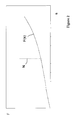
- FIG. 2 shows characteristic load displacement curves of the leaf spring assembly according to FIG. 1 ;
- FIG. 3 shows a second example of a leaf spring assembly for a wheel suspension of a motor vehicle in a three-dimensional view
- FIG. 3B shows the leaf spring assembly of FIG. 3A in a plan view
- FIG. 3C shows the leaf spring assembly of FIG. 3A in a side view
- FIG. 3D shows the leaf spring assembly of FIG. 3A with the first bearing in a stress-relieved condition
- FIG. 3E shows the leaf spring assembly of FIG. 3A with the first bearing in a first stopped position
- FIG. 3F shows the leaf spring assembly of FIG. 3A with the first bearing in a second stopped position
- FIG. 4 shows the characteristic load displacement curves of the leaf spring assembly according to FIG. 3A with different stop settings
- FIG. 5 shows a third example of a leaf spring assembly for a wheel suspension of a motor vehicle in a three-dimensional view
- FIG. 5B shows the leaf spring assembly of FIG. 5A in a plan view
- FIG. 5C shows the leaf spring assembly of FIG. 5A in a side view
- FIG. 6 shows a fourth example of a leaf spring assembly for a wheel suspension of a motor vehicle in a three-dimensional view
- FIG. 6B shows the leaf spring assembly of FIG. 6A in a plan view
- FIG. 6C shows the leaf spring assembly of FIG. 6A in a side view.
- FIGS. 1A to 10 show a leaf spring assembly 2 in a first example.
- the leaf spring assembly 2 comprises a leaf spring 3 made of fibre-reinforced plastics for resiliently supporting a wheel carrier of a motor vehicle, a first receiving device 4 for supporting a first end portion 5 of the leaf spring 3 and a second receiving device 6 for supporting the second end portion 7 of the leaf spring.
- the leaf spring 3 comprises a first spring leg 8 and a second spring leg 10 , with the two spring legs 8 , 10 being connected to one another by a transition portion 9 .
- the second spring leg 10 ends with a second end portion 7 which is fixed in the second receiving device 6 .
- the first spring leg 8 serves to receive a wheel carrier, not illustrated, to which a vehicle wheel is fixed.
- the first spring leg 8 comprises a central receiving region 12 which comprises a thickness D 12 which is greater than that of the laterally adjoining regions.
- the upper side 13 and the underside 14 of the receiving region 12 comprise planar faces which, more particularly, extend parallel relative to one another. As a result of said planar faces, the mounting procedure is easy and there is ensured a uniform introduction of force from the wheel carrier into the leaf spring 3 .
- the receiving region 12 can comprise a length of 150 mm to 200 mm, for example.
- the main direction of extension of the first spring leg 8 is in the longitudinal direction of the motor vehicle and, respectively, in the horizontal direction, whereas the main direction of extension of the second spring leg 10 is in the vertical direction of the motor vehicle.
- the first end 5 can point in the direction of driving (forward), whereas the second end 7 is positioned at the rear end and, more particularly, points downwardly.
- the first and the second spring leg 8 , 10 can differ from one another in respect of their length and/or their curvature.
- the length of the spring portion 8 is greater, by a multiple, than that of the bendable portion 10 , with the ratio of the length of the spring portion relative to the length of the bendable portion preferably being greater than five and smaller than ten.
- the spring portion 8 in the unloaded installed state, which is shown with dashed line, comprises a lower convex curve and, respectively, an upper concave curvature, more particularly with a mean radius of curvature R 8 .
- the spring portion With the spring being loaded due to vertical forces introduced, the spring portion is acted upon upwardly, whereby initially bending and compressive stresses are generated up to reaching a neutral position in which the spring portion is substantially straight.
- the curvature of the spring portion 8 changes, i.e. it gets a lower concave and upper convex curvature.
- the bending stresses in the spring portion 8 With exceeding the neutral position the bending stresses in the spring portion 8 are superimposed by tensile stresses. Thereby, the tensile stresses increase with an increasing load and thus increasing elastic deformation of the leaf spring 3 which leads to a progressive spring characteristic.
- the loaded mounted condition at maximum deflection is drawn in with dashed lines. It can be seen that the spring portion 8 is clearly curved upwards and that the bendable portion 10 is bent towards the first receiving device 4 .
- the first spring leg 8 via the transition portion 9 , changes into the second spring leg 10 , with the second spring leg 10 comprising a lower concave and, respectively, an upper convex curvature.
- a change in curvature of the leaf spring extension takes place in the transition portion 9 .
- the first spring leg 8 which is also referred to as the spring portion, the transition portion 9 , and the second spring leg, which is also referred to as the bendable portion
- the radius R 8 of the spring portion 8 is greater, by a multiple, than the radius R 9 of the transition portion 9 and greater than the radius R 10 of the bendable portion 10 .
- the first receiving device 4 is designed such that the first end 5 of the leaf spring 3 is received therein in a non-displaceable and moment-free way. More particularly, it is proposed that the first end 5 is held so as to be substantially stiff in a displacement sense with reference to all three axes (x, y, z).
- the non-displaceable bearing is to comprise slight displacements of up to 20 mm, which, for example, can result from an elastic deformation of the receiving device when the spring is under load.
- the moment-free support is accomplished in that the end portion 5 is supported so as to be pivotable around the pivot axis X 4 of the first receiving device 4 .
- the pivot axis X 4 extends approximately transversely to the longitudinal vehicle axis, with certain angular deviations being conceivable. More particularly, it is proposed that the spring end 5 is pivotable relative to the receiving device by a minimum of 10° and/or a maximum of 60°, preferably by an angle of rotation of 25° to 45°. Relative to the other two axes (y, z), the spring end 5 is held so as to be substantially stiff in a rotational sense, i.e. it is not pivotable.
- the first receiving device 4 comprises a receiving member 15 which, relative to a fixed carrier 16 , is supported by suitable bearing means 17 so as to be rotatable around the pivot axis X 4 ; as well as a clamping member 18 which is releasably connectable to the receiving member 15 by bolted connections 19 for example.
- the first end portion 5 of the leaf spring 3 is wedge-shaped and its thickness increases towards its end. In this way, the end portion 5 is effectively prevented from slipping out of the first receiving device 4 , even if the leaf spring is under maximum load.
- the pivotable, moment-free support of the first end portion of the leaf spring 3 leads to a reduction in forces in the receiving device 4 which are effective between the spring and the receiving device.
- the opposed second end portion 7 is received in the second receiving device 6 , with the second receiving device 6 forming a moment-resistant and non-displaceable bearing for the second end 7 .
- the second receiving device 6 comprises a receiving member 20 which is to be connected to a stationary component, as well as a clamping member 22 which is releasably connectable to the receiving member 20 , for example by bolted connections 23 .
- the second end portion 7 is fixedly clamped in between the clamping member 22 and the receiving member 20 , wherein also in this case it is proposed in particular that the leaf spring 3 widens in a wedge-shaped way towards its end. In this way, secure fixing conditions are ensured, even under maximum loads.
- the leaf spring 3 along its length, features a substantially constant width B 3 , whereas the thickness D 3 is variable along its length.
- Locally thickened portions especially in the region of the end portions 5 , 7 or in the central region 12 ensure a reduction in tension.
- the locally thickened portions can be achieved for example by additional layers of pre-pregs in the respective regions.
- the leaf spring 3 can be produced in one piece, for example by a pressing process involving the use of uni-directional, pre-impregnated fibres, so-called pre-pregs with a duroplastic or thermoplastic matrix.
- a pressing process involving the use of uni-directional, pre-impregnated fibres, so-called pre-pregs with a duroplastic or thermoplastic matrix.
- Other production processes such as resin injection moulding (RMT) are also possible.
- FIG. 2 shows a force path characteristic curve F(s) of the leaf spring assembly 2 according to FIG. 1 .
- the Y-axis shows the force F and, on the X-axis, the displacement s. It can be seen that the force F increases with an increasing spring travel s. With an increasing motor vehicle load and an increasing spring deflection, respectively, said progressive characteristic spring curve leads to a stiffer suspension, which advantageously affects the driving comfort and the driving stability of the motor vehicle.
- the neutral position N in which the spring portion 8 is substantially straight respectively free from compressive and tensile stresses, is shown with dashed line in FIG. 2 .
- the spring portion In the spring travel range up to reaching the neutral position N, the spring portion is curved convex on the downside. In this area, which is left of the neutral position N, the spring rate F(s) of the lead spring 3 is substantially constant. In particular, bending stresses and compressive stresses are present in the spring portion 8 which are reduced with increasing elastic deformation up to reaching the neutral position N.
- the course of the characteristic force displacement curve F(s) of the leaf spring assembly can be influenced by appropriately designing the leaf spring 3 in respect of its physical characteristics such as the length, width and thickness of the individual leaf spring portions as well as the receiving devices 4 , 6 .
- associating the longer spring leg 8 and the shorter spring leg 10 , respectively, to the moment-free receiving device 4 and to the moment-resistant receiving device 6 , respectively is freely selectable.
- the moment-free support of the long spring leg 8 and a moment-resistant support of the short spring leg 10 there occur relatively low spring forces in the leaf spring 3 which, accordingly, also feature relatively low spring rates.
- it is also possible to select different assemblies which will be referred to below in greater detail.
- FIGS. 3A to 3F which will be described jointly below, show a leaf spring assembly 3 in a second example which largely corresponds to the example according to FIG. 1 so that, as far as common features are concerned, reference is made to the above description. Identical components and components corresponding to one another have been given the same reference numbers as in FIG. 1 .
- a special design feature of the present example according to FIGS. 3A to 3F is in the design of the first receiving device 4 . It is also designed for the purpose of providing a moment-free and displacement-resisting support for the first end portion 5 of the leaf spring 3 .
- a stop 24 is provided which limits a pivot moment of the receiving member 25 , and of the clamping member 18 , respectively, in the circumferential direction.
- the limit stop 24 comprises two plates 25 which are fixedly connected to the carrier 16 , for example by threaded connections. At the upper end of the stop plates there are provided threaded bores through which threaded bolts 26 are threaded.
- the threaded ends of the threaded bolts 26 cooperate with the clamping member 3 in such a way that the clamping member 18 , when the leaf spring 3 is under load and pivots around the pivot axis X 4 , stops against the pins ends.
- the limit stop 24 has the effect that the generally moment-free support is fixed, so that after the leaf spring 3 has reached the stop, any bending moments acting around the pivot axis X 4 are accommodated and supported by the first receiving device 4 .
- the progression of the characteristic force displacement curve F(s) of the leaf spring assembly 3 is displaced towards shorter distances (s).
- the limit stop 24 and thus the characteristic force displacement curve F(s) can be steplessly adjusted by rotating the threaded bolt 26 , as required.
- FIG. 3D shows the first receiving device 4 in a lateral view as a detail in the unloaded condition of the leaf spring 3 . It is possible to see a distance between the clamping member 18 and the end of the threaded bolt 26 .
- FIG. 3E shows the first receiving device 4 in a loaded condition of the leaf spring assembly 3 . It can be seen that, because of the load on the leaf spring 3 , the first spring leg 8 has been pivoted rotated around the pivot axis X 4 anti-clockwise until the clamping member 18 has come to stop against the end of the threaded pin 26 .
- the associated force displacement curve F(s) is shown in FIG. 4 in the form of a dashed line.
- the kink point 27 is drawn in with which a sudden increase in the spring force F is achieved.
- FIG. 3F shows the first receiving device 4 wherein the stop 24 becomes effective at an earlier stage, so that the rotational movement of the spring bearing is already inhibited at a shorter rotational travel.
- the threaded bolt 26 has been rotated further into the threaded bore of the carrier plate 25 , so that the clamping member 18 comes to rest against the stop 24 after a shorter spring travel.
- the associated characteristic force displacement curve F(s)′ is shown in FIG. 4 in the form of a continuous line. It can be seen that already at a short spring travel (s)′ the point 27 ′ is reached, from which point onwards a sudden increase in the force F′ occurs. Overall, there is thus achieved a steeper force displacement curve F(s)′ than in the case of a longer spring travel up to the switch-off point as shown in FIG. 3E .
- FIGS. 5A to 5C show a leaf spring assembly 2 in a further example which largely corresponds to the example according to FIG. 1 , so that as far as common features are concerned, reference is made to the above description. Therein, identical details and details corresponding to one another have been given the same reference numbers (with indices), as in FIG. 1 .
- a feature of the present example according to FIG. 5 is that the moment-free and the moment-resistant bearings have been exchanged relative to FIG. 1 , which means that the first receiving device 4 ′ forms a displacement-resistant and moment-resistant support for the spring end 5 , whereas the second receiving device 6 ′ forms a displacement-resistant and moment-free support for the second spring end.
- the term “displacement-resistant” may comprise slight displacements of the ends 5 , 7 in the longitudinal direction of the motor vehicle with the spring 3 being under load.
- the first end 5 with reference to all three axes (x, y, z)—is held so as to be substantially stiff, both in the displacement sense and in the rotational sense.
- the second end 7 is held to be movable in the rotational sense with reference to the transverse axis (x) and—with reference to the longitudinal axis and perpendicularly axes (y, z)—it is held so as to be at least substantially stiff in the rotational sense.
- the receiving member 15 ′ is fixedly connected to a carrier 16 , for instance to a chassis part, with “fixidly” meaning that no relative movements, such as displacement movements or pivot movements can take place between the receiving member 15 ′ and the carrier 16 .
- the end portion 5 of the leaf spring 3 is clamped in between the clamping member 18 ′ and the receiving member 15 ′, with tensioning bolts (not illustrated) being threaded into the respective threaded bores.
- the second receiving device 6 ′ in which the second end portion 7 of the leaf spring 3 is supported, is provided in the form of a moment-free bearing.
- a pivotable receiving member 20 ′ which is supported by a suitable bearing 17 ′ relative to a stationary carrier element 16 ′ so as to be pivotable around a pivot axis X 6 ′.
- the wedge-shaped end 7 of the leaf spring 3 is clamped in between the pivotable receiving member 20 ′ and the clamping member 22 ′, so that it is non-displaceable, but rotationally movable in the second receiving device 6 ′.
- the associated characteristic load displacement curve F(s) has a steeper progression than in the example according to FIG. 1 .
- FIGS. 6A to 6C which will be described jointly below, show a leaf spring assembly 2 in a further example which corresponds to a combination of the example according to FIG. 1 and according to FIG. 5 , so that, as far as common features are concerned, reference is made to the above description. Thereby, identical details and details corresponding to one another have been given the same reference numbers as in FIGS. 1 to 5 .
- the special feature of the present example according to FIG. 6 is that the first receiving device 4 and the second receiving device 6 ′ both form moment-free bearings.
- the first receiving device 4 for clamping in the end 5 of the first spring leg 8 is supported so as to be pivotable around the pivot axis X 4 .
- the opposed second end 7 of the second spring leg 10 accordingly, is supported in the receiving device 6 so as to be pivotable around the pivot axis X 6 .
- At both spring ends 5 , 7 there should preferably be a pivotability of a minimum of 10° and/or a maximum of 60° relative to the associated receiving device, preferably of 25° to 45°.
- the two ends 5 , 7 of the leaf spring 3 are each non-displaceably clamped into the two receiving devices 4 , 6 ′ in the longitudinal direction, and in this case, too, the above definition of a “non-displaceable bearing” applies.
- the wedge-shaped ends 5 , 7 are each fixed between the receiving member 15 , 20 ′ and the clamping member 18 , 22 ′.
- the characteristic force displacement curve F(s) of the leaf spring assembly 2 has a particularly flat course.
- An advantage of the leaf spring assembly 2 is that, due to the end portions 5 , 7 being fixed in a non-displaceable way, the leaf spring 3 can be subjected to both bending and tensioning loads.
- the tensile and bending stresses occurring in the spring 3 are superimposed on one another and, together, lead to a progressive characteristic spring curve F(s).
- the tensile forces are generated in that the end portions 5 , 7 are axially fixedly clamped in in the longitudinal direction.
- said end portions 5 , 7 as a result, cannot move towards one another, which leads to a progressive characteristic spring curve.
- the moment-free support of at least one of the end portions 5 , 7 leads to reduced stresses in the leaf spring, as compared to a moment-resistant support.
Landscapes
- Engineering & Computer Science (AREA)
- Mechanical Engineering (AREA)
- General Engineering & Computer Science (AREA)
- Springs (AREA)
- Vehicle Body Suspensions (AREA)
Abstract
Description
Claims (18)
Applications Claiming Priority (4)
| Application Number | Priority Date | Filing Date | Title |
|---|---|---|---|
| DE102013107889 | 2013-07-23 | ||
| DE102013107889.3 | 2013-07-23 | ||
| DE102013107889.3A DE102013107889A1 (en) | 2013-07-23 | 2013-07-23 | Leaf spring assembly for motor vehicles |
| PCT/EP2014/065801 WO2015011181A1 (en) | 2013-07-23 | 2014-07-23 | Leaf spring arrangement for motor vehicles |
Publications (2)
| Publication Number | Publication Date |
|---|---|
| US20160159181A1 US20160159181A1 (en) | 2016-06-09 |
| US9868330B2 true US9868330B2 (en) | 2018-01-16 |
Family
ID=51212867
Family Applications (1)
| Application Number | Title | Priority Date | Filing Date |
|---|---|---|---|
| US14/905,840 Active US9868330B2 (en) | 2013-07-23 | 2014-07-23 | Leaf spring assembly for motor vehicles |
Country Status (7)
| Country | Link |
|---|---|
| US (1) | US9868330B2 (en) |
| EP (1) | EP2885554B1 (en) |
| JP (1) | JP6373375B2 (en) |
| CN (1) | CN105492796B (en) |
| DE (1) | DE102013107889A1 (en) |
| ES (1) | ES2611552T3 (en) |
| WO (1) | WO2015011181A1 (en) |
Cited By (2)
| Publication number | Priority date | Publication date | Assignee | Title |
|---|---|---|---|---|
| US11607922B2 (en) * | 2018-02-14 | 2023-03-21 | Hendrickson Commercial Vehicle Systems GmbH | Spring for use in conjunction with a vehicle |
| US12319104B2 (en) * | 2022-07-06 | 2025-06-03 | Hyundai Motor Company | Suspension having leaf spring |
Families Citing this family (21)
| Publication number | Priority date | Publication date | Assignee | Title |
|---|---|---|---|---|
| DE102014202581A1 (en) * | 2014-02-12 | 2015-08-13 | Muhr Und Bender Kg | Leaf spring and leaf spring arrangement |
| AT516932A1 (en) * | 2015-02-23 | 2016-09-15 | Hendrickson France S A S | Pen for a vehicle |
| DE102016006641A1 (en) | 2016-06-02 | 2017-12-07 | Daimler Ag | Leaf spring for a vehicle |
| DE102016216149B4 (en) | 2016-08-29 | 2024-10-02 | Ford Global Technologies, Llc | suspension system |
| CN108058558B (en) * | 2016-11-05 | 2019-08-06 | 刘守银 | Vertical FRP leaf spring body and its assembly structure |
| CN106704434B (en) * | 2016-12-28 | 2018-11-02 | 博戈橡胶塑料(株洲)有限公司 | Automobile major-minor formula flat spring assembly and its manufacturing method and design method |
| DE102017206020B4 (en) | 2017-04-07 | 2022-09-08 | Ford Global Technologies, Llc | Leaf spring assembly for motor vehicles |
| US10421021B2 (en) | 2017-05-03 | 2019-09-24 | Disney Enterprises, Inc. | Roller coaster vehicle guidance system including a side guide assembly with wheel suspension |
| WO2018211298A1 (en) * | 2017-05-15 | 2018-11-22 | Volvo Truck Corporation | A suspension system of a vehicle axle |
| DE102017217598B4 (en) * | 2017-10-04 | 2021-05-27 | Ford Global Technologies, Llc | Spring assembly |
| DE102018202750A1 (en) * | 2018-02-23 | 2019-08-29 | Ford Global Technologies, Llc | Leaf spring of multilayer, fiber-reinforced plastic material for motor vehicles and leaf spring arrangement with leaf spring |
| CN108583189A (en) * | 2018-04-28 | 2018-09-28 | 安徽江淮汽车集团股份有限公司 | A kind of FRP composite materials major-minor spring assembly |
| DE102018123082B4 (en) * | 2018-09-19 | 2020-07-30 | Muhr Und Bender Kg | Leaf spring assembly for a vehicle wheel suspension |
| FR3095985B1 (en) * | 2019-05-17 | 2021-05-28 | Renault Sas | Suspension element of a vehicle |
| DE102019209917A1 (en) * | 2019-07-05 | 2021-01-07 | Ford Global Technologies, Llc | Axle suspension for a vehicle |
| DE102019209977A1 (en) * | 2019-07-08 | 2021-01-14 | Ford Global Technologies, Llc | Axle suspension for a vehicle |
| US11143231B2 (en) * | 2019-07-26 | 2021-10-12 | The Boeing Company | Blade flexure assembly with replaceable elements |
| DE102019212696A1 (en) * | 2019-08-23 | 2021-02-25 | Ford Global Technologies, Llc | Axle suspension for a vehicle |
| DE102019131536B3 (en) * | 2019-11-21 | 2021-03-25 | Ford Global Technologies Llc | Pre-tensioning device for pre-tensioning a backrest and vehicle |
| DE102021106716A1 (en) * | 2021-03-18 | 2022-09-22 | Rheinmetall Invent GmbH | Leaf spring device, chassis and vehicle |
| WO2025127096A1 (en) * | 2023-12-13 | 2025-06-19 | 日本発條株式会社 | Vehicle suspension device |
Citations (29)
| Publication number | Priority date | Publication date | Assignee | Title |
|---|---|---|---|---|
| US1182181A (en) | 1916-01-20 | 1916-05-09 | Arthur M Laycock | Automobile-spring. |
| DE898154C (en) | 1951-12-20 | 1953-11-26 | Maschf Augsburg Nuernberg Ag | Cushioning of rail vehicles, especially those in lightweight construction |
| US3022991A (en) | 1960-03-03 | 1962-02-27 | Anthony F Billard | Spring and shackle connector |
| US3685812A (en) | 1970-09-02 | 1972-08-22 | Chrysler Corp | Vehicle spring |
| US4512559A (en) * | 1980-05-01 | 1985-04-23 | Kabushiki Kaisha Toyota Chuo Kenkyusho | Leaf spring construction |
| US4637594A (en) * | 1981-10-29 | 1987-01-20 | Horikiri Spring Mfg. Co., Ltd. | Leaf spring construction |
| DE3613804C1 (en) | 1986-04-24 | 1987-07-09 | Audi Ag | Device with a flat component made of fiber-reinforced plastic and an end force introduction part |
| DE3637281A1 (en) | 1986-11-03 | 1988-01-28 | Daimler Benz Ag | Spring bracket which can be fixed on the frame of a chassis |
| US4802659A (en) | 1986-07-17 | 1989-02-07 | British Petroleum Company P.L.C. | Leaf spring |
| WO1990003281A1 (en) | 1988-09-20 | 1990-04-05 | Ab Volvo | A leaf spring |
| US4969633A (en) * | 1983-10-19 | 1990-11-13 | A. O. Smith Corporation | Molded fiber reinforced plastic leaf spring |
| JPH0319626A (en) | 1989-06-14 | 1991-01-28 | Shoji Shimazaki | Netted pot for transplanting of plant, material used for same device and production thereof |
| EP0425880A1 (en) | 1989-10-27 | 1991-05-08 | BASF Aktiengesellschaft | Leaf spring of fibre-reinforced material |
| US5351986A (en) * | 1993-04-14 | 1994-10-04 | Hedenberg William E | Vehicle air suspension system |
| DE4411286C2 (en) | 1994-03-31 | 1999-08-12 | Daimler Benz Ag | Leaf spring for vehicles |
| EP0752934B1 (en) | 1994-03-31 | 2000-07-19 | Detroit Steel Products Co.Inc. | Vehicle suspension system |
| JP2002059725A (en) | 2000-08-17 | 2002-02-26 | Hyundai Motor Co Ltd | Suspension device for vehicle improving turning stability |
| US6361026B2 (en) * | 1994-03-31 | 2002-03-26 | Detroit Steel Products Co., Inc. | Vehicle suspension system |
| US20020101012A1 (en) | 2001-01-29 | 2002-08-01 | Giovanni Greco | Composite bow mono-leaf spring |
| US20030080527A1 (en) | 2001-10-26 | 2003-05-01 | Bryant Peter E. | Opposing spring rebound tension suspension system |
| JP2004306805A (en) | 2003-04-08 | 2004-11-04 | Hino Motors Ltd | Suspension device |
| US20050051933A1 (en) * | 2003-09-05 | 2005-03-10 | Platner David K. | Composite leaf spring having an arcuate attachment arrangement for vehicle mounting |
| US20060103103A1 (en) * | 2004-11-12 | 2006-05-18 | Land Jonathan L | Lightweight, low part-count, suspension system for wheeled vehicles |
| US20080252033A1 (en) | 2007-04-10 | 2008-10-16 | Platner David K | Composite spring with resilient attachment interface |
| DE102009015662B3 (en) | 2009-03-31 | 2010-10-21 | Ifc Composite Gmbh | Suspension arrangement for motor vehicle, has catches fastened to bearing support or integrally formed with bearing support such that clamping body is supportable with leaf spring-far surface at catch |
| DE102009032919A1 (en) | 2009-07-14 | 2011-02-03 | Ifc Composite Gmbh | Suspension arrangement has leaf spring made of fiber composite material, which has central section and two ends axially adjacent |
| DE102010015951A1 (en) | 2010-03-12 | 2011-09-15 | Muhr Und Bender Kg | Leaf spring for motor vehicles |
| JP2012051403A (en) | 2010-08-31 | 2012-03-15 | Hino Motors Ltd | Suspension device |
| EP2570694A1 (en) | 2010-05-14 | 2013-03-20 | NHK Spring Co.,Ltd. | Fiber-reinforced plastic spring |
Family Cites Families (3)
| Publication number | Priority date | Publication date | Assignee | Title |
|---|---|---|---|---|
| JPH0319626Y2 (en) * | 1986-05-09 | 1991-04-25 | ||
| JP2003237335A (en) * | 2002-02-20 | 2003-08-27 | Hino Motors Ltd | Suspension structure |
| CN102667219A (en) * | 2009-10-26 | 2012-09-12 | 雷诺索尔公司 | Composite leaf spring |
-
2013
- 2013-07-23 DE DE102013107889.3A patent/DE102013107889A1/en active Pending
-
2014
- 2014-07-23 EP EP14741910.5A patent/EP2885554B1/en active Active
- 2014-07-23 CN CN201480041712.6A patent/CN105492796B/en active Active
- 2014-07-23 ES ES14741910.5T patent/ES2611552T3/en active Active
- 2014-07-23 WO PCT/EP2014/065801 patent/WO2015011181A1/en not_active Ceased
- 2014-07-23 JP JP2016528518A patent/JP6373375B2/en active Active
- 2014-07-23 US US14/905,840 patent/US9868330B2/en active Active
Patent Citations (36)
| Publication number | Priority date | Publication date | Assignee | Title |
|---|---|---|---|---|
| US1182181A (en) | 1916-01-20 | 1916-05-09 | Arthur M Laycock | Automobile-spring. |
| DE898154C (en) | 1951-12-20 | 1953-11-26 | Maschf Augsburg Nuernberg Ag | Cushioning of rail vehicles, especially those in lightweight construction |
| US3022991A (en) | 1960-03-03 | 1962-02-27 | Anthony F Billard | Spring and shackle connector |
| US3685812A (en) | 1970-09-02 | 1972-08-22 | Chrysler Corp | Vehicle spring |
| US4512559A (en) * | 1980-05-01 | 1985-04-23 | Kabushiki Kaisha Toyota Chuo Kenkyusho | Leaf spring construction |
| US4637594A (en) * | 1981-10-29 | 1987-01-20 | Horikiri Spring Mfg. Co., Ltd. | Leaf spring construction |
| US4969633A (en) * | 1983-10-19 | 1990-11-13 | A. O. Smith Corporation | Molded fiber reinforced plastic leaf spring |
| DE3613804C1 (en) | 1986-04-24 | 1987-07-09 | Audi Ag | Device with a flat component made of fiber-reinforced plastic and an end force introduction part |
| JPS62258804A (en) | 1986-04-24 | 1987-11-11 | アウデイ アクチエンゲゼルシヤフト | Leaf spring and control arm device for automobile |
| US4802659A (en) | 1986-07-17 | 1989-02-07 | British Petroleum Company P.L.C. | Leaf spring |
| DE3637281A1 (en) | 1986-11-03 | 1988-01-28 | Daimler Benz Ag | Spring bracket which can be fixed on the frame of a chassis |
| WO1990003281A1 (en) | 1988-09-20 | 1990-04-05 | Ab Volvo | A leaf spring |
| US5161785A (en) * | 1988-09-20 | 1992-11-10 | Ab Volvo | Leaf spring |
| JPH0319626A (en) | 1989-06-14 | 1991-01-28 | Shoji Shimazaki | Netted pot for transplanting of plant, material used for same device and production thereof |
| EP0425880A1 (en) | 1989-10-27 | 1991-05-08 | BASF Aktiengesellschaft | Leaf spring of fibre-reinforced material |
| US5351986A (en) * | 1993-04-14 | 1994-10-04 | Hedenberg William E | Vehicle air suspension system |
| DE4411286C2 (en) | 1994-03-31 | 1999-08-12 | Daimler Benz Ag | Leaf spring for vehicles |
| EP0752934B1 (en) | 1994-03-31 | 2000-07-19 | Detroit Steel Products Co.Inc. | Vehicle suspension system |
| US6361026B2 (en) * | 1994-03-31 | 2002-03-26 | Detroit Steel Products Co., Inc. | Vehicle suspension system |
| JP2002059725A (en) | 2000-08-17 | 2002-02-26 | Hyundai Motor Co Ltd | Suspension device for vehicle improving turning stability |
| US6428025B1 (en) | 2000-08-17 | 2002-08-06 | Hyundai Motor Company | Automotive suspension system for increasing roll safety |
| US20020101012A1 (en) | 2001-01-29 | 2002-08-01 | Giovanni Greco | Composite bow mono-leaf spring |
| US6435485B1 (en) * | 2001-01-29 | 2002-08-20 | Visteon Global Technologies, Inc. | Composite bow mono-leaf spring |
| DE10202114A1 (en) | 2001-01-29 | 2002-09-12 | Visteon Global Tech Inc | Composite-arm single-leaf |
| US20030080527A1 (en) | 2001-10-26 | 2003-05-01 | Bryant Peter E. | Opposing spring rebound tension suspension system |
| JP2004306805A (en) | 2003-04-08 | 2004-11-04 | Hino Motors Ltd | Suspension device |
| US20050051933A1 (en) * | 2003-09-05 | 2005-03-10 | Platner David K. | Composite leaf spring having an arcuate attachment arrangement for vehicle mounting |
| US20060103103A1 (en) * | 2004-11-12 | 2006-05-18 | Land Jonathan L | Lightweight, low part-count, suspension system for wheeled vehicles |
| US20080252033A1 (en) | 2007-04-10 | 2008-10-16 | Platner David K | Composite spring with resilient attachment interface |
| DE102009015662B3 (en) | 2009-03-31 | 2010-10-21 | Ifc Composite Gmbh | Suspension arrangement for motor vehicle, has catches fastened to bearing support or integrally formed with bearing support such that clamping body is supportable with leaf spring-far surface at catch |
| DE102009032919A1 (en) | 2009-07-14 | 2011-02-03 | Ifc Composite Gmbh | Suspension arrangement has leaf spring made of fiber composite material, which has central section and two ends axially adjacent |
| DE102010015951A1 (en) | 2010-03-12 | 2011-09-15 | Muhr Und Bender Kg | Leaf spring for motor vehicles |
| US20130049271A1 (en) * | 2010-03-12 | 2013-02-28 | Muhr Und Bender Kg | Leaf Spring for Motor Vehicles |
| EP2570694A1 (en) | 2010-05-14 | 2013-03-20 | NHK Spring Co.,Ltd. | Fiber-reinforced plastic spring |
| JP2012051403A (en) | 2010-08-31 | 2012-03-15 | Hino Motors Ltd | Suspension device |
| US20130127133A1 (en) | 2010-08-31 | 2013-05-23 | Nhk Spring Co., Ltd. | Suspension device |
Non-Patent Citations (2)
| Title |
|---|
| International Search Report and Written Opinion for PCT/EP2014/065801 dated Oct. 30, 2014 (with English translation; 16 pages). |
| SAE, AE-11 Spring Design Manual, Jan. 1, 1990, Chapter 6, Society of Automotive Engineers, Inc., Warrendale, PA (US). |
Cited By (2)
| Publication number | Priority date | Publication date | Assignee | Title |
|---|---|---|---|---|
| US11607922B2 (en) * | 2018-02-14 | 2023-03-21 | Hendrickson Commercial Vehicle Systems GmbH | Spring for use in conjunction with a vehicle |
| US12319104B2 (en) * | 2022-07-06 | 2025-06-03 | Hyundai Motor Company | Suspension having leaf spring |
Also Published As
| Publication number | Publication date |
|---|---|
| JP6373375B2 (en) | 2018-08-15 |
| US20160159181A1 (en) | 2016-06-09 |
| EP2885554B1 (en) | 2016-10-26 |
| EP2885554A1 (en) | 2015-06-24 |
| ES2611552T3 (en) | 2017-05-09 |
| JP2016525478A (en) | 2016-08-25 |
| CN105492796B (en) | 2018-01-02 |
| DE102013107889A1 (en) | 2015-01-29 |
| CN105492796A (en) | 2016-04-13 |
| WO2015011181A1 (en) | 2015-01-29 |
Similar Documents
| Publication | Publication Date | Title |
|---|---|---|
| US9868330B2 (en) | Leaf spring assembly for motor vehicles | |
| US10059163B2 (en) | Leaf spring and leaf spring assembly | |
| US9217482B2 (en) | Leaf spring for motor vehicles | |
| CN102481818B (en) | Bearing equipment for transverse leaf springs | |
| US11001113B2 (en) | Dual-rate leaf spring suspension for a vehicle | |
| US8777248B2 (en) | Motor-vehicle suspension system with transverse control arms and central leaf spring connecting the arms | |
| CN102481817B (en) | Bearing mechanism for a transverse leaf spring | |
| US8950766B2 (en) | Axle suspension with longitudinal leaf spring for a motor vehicle | |
| US8814191B2 (en) | Leaf spring having a rigidly connected elastic connecting body for a motor vehicle | |
| KR20150082651A (en) | Axle for a motor vehicle | |
| CN109070671B (en) | Vehicle independent suspension with wheel-guiding leaf spring element made of fiber composite material | |
| US10427481B2 (en) | Motor vehicle wheel suspension | |
| US6435485B1 (en) | Composite bow mono-leaf spring | |
| US20140048988A1 (en) | Leaf spring assembly | |
| CN109664704A (en) | Longitudinal leaf spring device for motor vehicle body suspension | |
| KR20160124776A (en) | Suspension spring unit for a vehicle chassis | |
| US20190308477A1 (en) | Leaf spring holder for connecting a leaf spring to an axle and chassis with such a leaf spring holder | |
| US20180312026A1 (en) | Check rail with a pivot bearing | |
| CN106457943B (en) | Spring-guide rod arrangement | |
| CN109677222A (en) | Longitudinal plate spring device with buffering stopper unit | |
| WO2026053069A1 (en) | Suspension system for a motor vehicle including a pair of oscillating arms, a transverse leaf spring, and related connection units | |
| CA2968178C (en) | Spring for a vehicle |
Legal Events
| Date | Code | Title | Description |
|---|---|---|---|
| AS | Assignment |
Owner name: MUHR UND BENDER KG, GERMANY Free format text: ASSIGNMENT OF ASSIGNORS INTEREST;ASSIGNORS:HAHN, CHRISTOPH;FORSTER, RAINER;KOBELEV, VLADIMIR, DR.;AND OTHERS;SIGNING DATES FROM 20160125 TO 20160127;REEL/FRAME:037670/0522 |
|
| STCF | Information on status: patent grant |
Free format text: PATENTED CASE |
|
| MAFP | Maintenance fee payment |
Free format text: PAYMENT OF MAINTENANCE FEE, 4TH YEAR, LARGE ENTITY (ORIGINAL EVENT CODE: M1551); ENTITY STATUS OF PATENT OWNER: LARGE ENTITY Year of fee payment: 4 |
|
| IPR | Aia trial proceeding filed before the patent and appeal board: inter partes review |
Free format text: TRIAL NO: IPR2022-00278 Opponent name: RASSINI SUSPENSIONES, S.A. DE C.V., AND RASSINI INTERNATIONAL, INC. Effective date: 20211222 |
|
| RF | Reissue application filed |
Effective date: 20240927 |
|
| MAFP | Maintenance fee payment |
Free format text: PAYMENT OF MAINTENANCE FEE, 8TH YEAR, LARGE ENTITY (ORIGINAL EVENT CODE: M1552); ENTITY STATUS OF PATENT OWNER: LARGE ENTITY Year of fee payment: 8 |
|
| IPRC | Trial and appeal board: inter partes review certificate |
Kind code of ref document: K1 Free format text: INTER PARTES REVIEW CERTIFICATE; TRIAL NO. IPR2022-00278, DEC. 22, 2021 INTER PARTES REVIEW CERTIFICATE FOR PATENT 9,868,330, ISSUED JAN. 16, 2018, APPL. NO. 14/905,840, JAN. 18, 2016 INTER PARTES REVIEW CERTIFICATE ISSUED SEP. 4, 2025 Effective date: 20250904 |