US9859082B2 - Device for connecting an electrical conductor having an eyelet tag to the connecting pad of a terminal of electrical apparatus, and apparatus including such a device - Google Patents
Device for connecting an electrical conductor having an eyelet tag to the connecting pad of a terminal of electrical apparatus, and apparatus including such a device Download PDFInfo
- Publication number
- US9859082B2 US9859082B2 US15/340,644 US201615340644A US9859082B2 US 9859082 B2 US9859082 B2 US 9859082B2 US 201615340644 A US201615340644 A US 201615340644A US 9859082 B2 US9859082 B2 US 9859082B2
- Authority
- US
- United States
- Prior art keywords
- screw
- nut
- head
- terminal
- tag
- Prior art date
- Legal status (The legal status is an assumption and is not a legal conclusion. Google has not performed a legal analysis and makes no representation as to the accuracy of the status listed.)
- Active
Links
- 239000004020 conductor Substances 0.000 title claims abstract description 11
- 230000037431 insertion Effects 0.000 claims description 3
- 238000003780 insertion Methods 0.000 claims description 3
- 230000001360 synchronised effect Effects 0.000 description 3
- 230000008878 coupling Effects 0.000 description 1
- 238000010168 coupling process Methods 0.000 description 1
- 238000005859 coupling reaction Methods 0.000 description 1
- 230000000717 retained effect Effects 0.000 description 1
Images


Classifications
-
- H—ELECTRICITY
- H01—ELECTRIC ELEMENTS
- H01R—ELECTRICALLY-CONDUCTIVE CONNECTIONS; STRUCTURAL ASSOCIATIONS OF A PLURALITY OF MUTUALLY-INSULATED ELECTRICAL CONNECTING ELEMENTS; COUPLING DEVICES; CURRENT COLLECTORS
- H01R4/00—Electrically-conductive connections between two or more conductive members in direct contact, i.e. touching one another; Means for effecting or maintaining such contact; Electrically-conductive connections having two or more spaced connecting locations for conductors and using contact members penetrating insulation
- H01R4/28—Clamped connections, spring connections
- H01R4/30—Clamped connections, spring connections utilising a screw or nut clamping member
- H01R4/301—Clamped connections, spring connections utilising a screw or nut clamping member having means for preventing complete unscrewing of screw or nut
-
- H—ELECTRICITY
- H01—ELECTRIC ELEMENTS
- H01H—ELECTRIC SWITCHES; RELAYS; SELECTORS; EMERGENCY PROTECTIVE DEVICES
- H01H71/00—Details of the protective switches or relays covered by groups H01H73/00 - H01H83/00
- H01H71/08—Terminals; Connections
-
- F—MECHANICAL ENGINEERING; LIGHTING; HEATING; WEAPONS; BLASTING
- F16—ENGINEERING ELEMENTS AND UNITS; GENERAL MEASURES FOR PRODUCING AND MAINTAINING EFFECTIVE FUNCTIONING OF MACHINES OR INSTALLATIONS; THERMAL INSULATION IN GENERAL
- F16B—DEVICES FOR FASTENING OR SECURING CONSTRUCTIONAL ELEMENTS OR MACHINE PARTS TOGETHER, e.g. NAILS, BOLTS, CIRCLIPS, CLAMPS, CLIPS OR WEDGES; JOINTS OR JOINTING
- F16B41/00—Measures against loss of bolts, nuts, or pins; Measures against unauthorised operation of bolts, nuts or pins
- F16B41/002—Measures against loss of bolts, nuts or pins
-
- H—ELECTRICITY
- H01—ELECTRIC ELEMENTS
- H01R—ELECTRICALLY-CONDUCTIVE CONNECTIONS; STRUCTURAL ASSOCIATIONS OF A PLURALITY OF MUTUALLY-INSULATED ELECTRICAL CONNECTING ELEMENTS; COUPLING DEVICES; CURRENT COLLECTORS
- H01R11/00—Individual connecting elements providing two or more spaced connecting locations for conductive members which are, or may be, thereby interconnected, e.g. end pieces for wires or cables supported by the wire or cable and having means for facilitating electrical connection to some other wire, terminal, or conductive member, blocks of binding posts
- H01R11/11—End pieces or tapping pieces for wires, supported by the wire and for facilitating electrical connection to some other wire, terminal or conductive member
- H01R11/12—End pieces terminating in an eye, hook, or fork
-
- H—ELECTRICITY
- H01—ELECTRIC ELEMENTS
- H01R—ELECTRICALLY-CONDUCTIVE CONNECTIONS; STRUCTURAL ASSOCIATIONS OF A PLURALITY OF MUTUALLY-INSULATED ELECTRICAL CONNECTING ELEMENTS; COUPLING DEVICES; CURRENT COLLECTORS
- H01R4/00—Electrically-conductive connections between two or more conductive members in direct contact, i.e. touching one another; Means for effecting or maintaining such contact; Electrically-conductive connections having two or more spaced connecting locations for conductors and using contact members penetrating insulation
- H01R4/28—Clamped connections, spring connections
- H01R4/30—Clamped connections, spring connections utilising a screw or nut clamping member
- H01R4/34—Conductive members located under head of screw
Definitions
- the present invention concerns a device for connecting a conductor including a so-called eyelet tag to the connecting pad of a terminal of electrical apparatus, including a screw adapted to slide inside the terminal in a direction substantially orthogonal to the direction of insertion of the conductor in the terminal, said screw having a first so-called head portion adapted to be actuated by a user and to be screwed into a head nut and a second so-called body portion adapted to be screwed into a so-called body nut mounted in the casing of the apparatus, said screw being mobile between an open position in which the screw is screwed only into the head nut so as to allow the introduction of the tag into the terminal between the screw body and the pad and a closed position in which the screw is screwed into both the body nut and the head nut so as to clamp the tag between this screw body and the connecting pad.
- the present invention solves these problems and proposes a device for connecting a conductor including an eyelet tag, that device having the advantage of including a captive screw, the product incorporating this device being able to be shipped with the connection open.
- the present invention consists in a connecting device of the kind referred to above, that device being characterized in that it comprises means for synchronizing the threads respectively associated with the screw body and the screw head, these means ensuring automatic returning of the screw body towards the screw head when the screw body is brought into contact with the body nut during screwing until synchronization of the two threads
- the head nut is fixedly mounted in the casing B of the apparatus, whereas the body nut is adapted to be moved in a direction corresponding to the direction of screwing in the screw when that screw comes into contact with the screw body and before the synchronization of the threads.
- these means include a spring disposed between a wall of the casing and the body nut and adapted to return said nut into its initial position after the aforementioned movement of said nut in the direction of screwing in before synchronization of the threads.
- the two nuts are arranged relative to the screw so that, at a certain moment during screwing in, the no-load torque generated at the time of the connection is no longer composed only of friction between the screw and the body nut, this making it possible to render reliable the residual torque for the clamping of the eyelet tag, the body nut then being pressed against the pad by the spring.
- the screw includes between the head and the body a flange adapted to have one of its radial faces come to bear on the tag in the clamping position of the screw and its opposite radial face to come to bear on the head nut during unscrewing of the screw so as to retain said screw inside the terminal in the open position.
- the screw includes between the flange and the free end of the screw head and adjoining said flange a groove that is unthreaded, this groove making it possible to produce a disengagement making it possible to render reliable the position of the flange relative to the head nut in the maximum open position of the terminal and not to have to provide any force for screwing in.
- the present invention further consists in electrical protection apparatus having the features referred to above separately or in combination.
- that apparatus is a circuit-breaker.
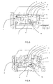
- FIGS. 1 to 6 are partial views in section showing the interior part of a terminal including a connecting device according to one particular embodiment of the invention in various screwing positions running from the open position to the closed position of the terminal, this latter position corresponding to a connected position of the conductor.
- This terminal is housed in an opening 1 provided in the casing B of the apparatus, this terminal also housing an electrical connection pad 2 belonging to the apparatus.
- This connecting device includes in a manner known in itself a screw 3 adapted to slide in the casing B of the apparatus in a direction substantially orthogonal to the direction of insertion of the conductor 4 into the terminal.
- This screw 3 includes a so-called head part 3 a adapted to be screwed into a head nut 5 and a second, so-called body part 3 b adapted to be screwed into a body nut 6 at the end of screwing it in, the terminal 7 being mounted around the body part 3 b and adapted to be gripped between that body part 3 b and the connecting pad 2 .
- This head nut 5 is fixedly mounted relative to the casing of the apparatus whereas this body nut 6 is mounted to slide slightly relative to the casing so as to allow slight movement of this nut toward the side opposite the connecting pad.
- this device includes respective means for synchronizing the threads provided on the two screw parts after the body part 3 b is brought into contact with the body nut 6 .
- these means include a spring 8 mounted in the opening 1 between a wall of the casing and the aforementioned body nut 6 so as to be able to return the body nut into its initial position after the latter has been moved by the screw 3 while bringing the screw body 3 b into contact with the body nut 6 and before synchronization of the two threads.
- This screw body 3 b also includes a flange 9 adapted to cooperate with this head nut 5 so as to prevent the removal of the screw 3 from the terminal 7 in the open position of the terminal 7 .
- This flange 9 advantageously has an exterior surface of partially cylindrical shape and the head nut 5 advantageously has an exterior surface of rectangular section.
- This screw body 3 b also includes, after the flange 9 on the side opposite the connecting pad 2 , a groove 10 with no threads intended to enable disengagement of the screw.
- the connecting device D is in an open position.
- the screw 3 In this initial position, the screw 3 is unscrewed as far as possible, leaving the terminal in the open position.
- the groove 10 with no threads provided at the level of the flange 9 of the screw 3 enables disengagement of the screw, which therefore makes it possible to render reliable the position of the flange 9 relative to that of the head nut 5 and not to have to provide any effort for subsequently screwing it in.
- the device In FIG. 2 , the device is in a so-called starting position. In this position, after starting to screw in the screw 3 , the latter has been able to move into the interior of the head nut 5 and the screw 3 comes into contact with the body nut 6 .
- the device is in a thread synchronization position.
- the spring 8 serves as a return spring in order to compensate these movements of the body nut 6 by urging the latter nut in the direction of the head 3 a of the screw.
- the screw 3 is in a so-called double-engagement position. In this position, once the threads have been synchronized and interengaged, the screw 3 is again in double engagement with the head nut 5 and the body nut 6 during a brief phase of movement.
- the body nut 6 is still in a so-called push back position, the spring 8 still being compressed.
- the device In FIG. 6 , the device is in a closed position.
- the invention therefore makes it possible to provide a product that is directly available for making a connection, the screw being a captive screw and retained inside the envelope.
- the invention also makes it possible to disengage the screw in the completely open position of the terminal.
- the invention applies to any device for connecting a conductor including an eyelet tag in electrical apparatus.
Abstract
A device for connecting a conductor to a terminal, including a screw slidable inside the terminal of an apparatus, the screw having a first head portion to be actuated and screwed into a head nut and a second body portion to be screwed into a body nut mounted in a casing of the apparatus, the screw being mobile between an open position in which the screw is screwed only into the head nut so as to allow the introduction of a tag into the terminal between the screw body and a pad and a closed position in which the screw is screwed into both the body nut and the head nut so as to clamp the tag between this screw body and the pad. This device includes a device for synchronizing the threads respectively associated with the screw body and the screw head, this device ensuring automatic returning of the screw body towards the screw head when the screw body is brought into contact with the body nut during screwing until synchronization of the two threads.
Description
The present invention concerns a device for connecting a conductor including a so-called eyelet tag to the connecting pad of a terminal of electrical apparatus, including a screw adapted to slide inside the terminal in a direction substantially orthogonal to the direction of insertion of the conductor in the terminal, said screw having a first so-called head portion adapted to be actuated by a user and to be screwed into a head nut and a second so-called body portion adapted to be screwed into a so-called body nut mounted in the casing of the apparatus, said screw being mobile between an open position in which the screw is screwed only into the head nut so as to allow the introduction of the tag into the terminal between the screw body and the pad and a closed position in which the screw is screwed into both the body nut and the head nut so as to clamp the tag between this screw body and the connecting pad.
Known products including these connecting devices are shipped with their terminals in the closed position. The installer therefore has to unscrew the screw completely before making the connection. Then, once entirely unscrewed, the screw is separated from the product, which then leads to the risk of dropping and losing the screw. It is then necessary to install the eyelet tag and to connect it to the pad using the screw. This may prove difficult because of the restricted space and the fact that the screw is held only by the head of the screwdriver.
The present invention solves these problems and proposes a device for connecting a conductor including an eyelet tag, that device having the advantage of including a captive screw, the product incorporating this device being able to be shipped with the connection open.
To this end, the present invention consists in a connecting device of the kind referred to above, that device being characterized in that it comprises means for synchronizing the threads respectively associated with the screw body and the screw head, these means ensuring automatic returning of the screw body towards the screw head when the screw body is brought into contact with the body nut during screwing until synchronization of the two threads
According to one particular feature, the head nut is fixedly mounted in the casing B of the apparatus, whereas the body nut is adapted to be moved in a direction corresponding to the direction of screwing in the screw when that screw comes into contact with the screw body and before the synchronization of the threads.
According to another feature, these means include a spring disposed between a wall of the casing and the body nut and adapted to return said nut into its initial position after the aforementioned movement of said nut in the direction of screwing in before synchronization of the threads.
According to another feature, the two nuts are arranged relative to the screw so that, at a certain moment during screwing in, the no-load torque generated at the time of the connection is no longer composed only of friction between the screw and the body nut, this making it possible to render reliable the residual torque for the clamping of the eyelet tag, the body nut then being pressed against the pad by the spring.
According to another feature, the screw includes between the head and the body a flange adapted to have one of its radial faces come to bear on the tag in the clamping position of the screw and its opposite radial face to come to bear on the head nut during unscrewing of the screw so as to retain said screw inside the terminal in the open position.
According to another feature, the screw includes between the flange and the free end of the screw head and adjoining said flange a groove that is unthreaded, this groove making it possible to produce a disengagement making it possible to render reliable the position of the flange relative to the head nut in the maximum open position of the terminal and not to have to provide any force for screwing in.
The present invention further consists in electrical protection apparatus having the features referred to above separately or in combination.
According to one particular feature, that apparatus is a circuit-breaker.
However, other particular features and advantages of the invention will become more apparent in the following detailed description referring to the appended drawings provided by way of example only and in which:
In the figures there has been represented a terminal belonging to a circuit-breaker, that terminal including a connecting device D according to one particular embodiment of the invention.
This terminal is housed in an opening 1 provided in the casing B of the apparatus, this terminal also housing an electrical connection pad 2 belonging to the apparatus.
This connecting device includes in a manner known in itself a screw 3 adapted to slide in the casing B of the apparatus in a direction substantially orthogonal to the direction of insertion of the conductor 4 into the terminal. This screw 3 includes a so-called head part 3 a adapted to be screwed into a head nut 5 and a second, so-called body part 3 b adapted to be screwed into a body nut 6 at the end of screwing it in, the terminal 7 being mounted around the body part 3 b and adapted to be gripped between that body part 3 b and the connecting pad 2. This head nut 5 is fixedly mounted relative to the casing of the apparatus whereas this body nut 6 is mounted to slide slightly relative to the casing so as to allow slight movement of this nut toward the side opposite the connecting pad.
According to the invention, this device includes respective means for synchronizing the threads provided on the two screw parts after the body part 3 b is brought into contact with the body nut 6. According to one particular embodiment, these means include a spring 8 mounted in the opening 1 between a wall of the casing and the aforementioned body nut 6 so as to be able to return the body nut into its initial position after the latter has been moved by the screw 3 while bringing the screw body 3 b into contact with the body nut 6 and before synchronization of the two threads.
This screw body 3 b also includes a flange 9 adapted to cooperate with this head nut 5 so as to prevent the removal of the screw 3 from the terminal 7 in the open position of the terminal 7. This flange 9 advantageously has an exterior surface of partially cylindrical shape and the head nut 5 advantageously has an exterior surface of rectangular section.
This screw body 3 b also includes, after the flange 9 on the side opposite the connecting pad 2, a groove 10 with no threads intended to enable disengagement of the screw.
The operation of a connecting device of this kind will be described hereinafter with reference to the figures.
In FIG. 1 , the connecting device D is in an open position.
In this initial position, the screw 3 is unscrewed as far as possible, leaving the terminal in the open position. The groove 10 with no threads provided at the level of the flange 9 of the screw 3 enables disengagement of the screw, which therefore makes it possible to render reliable the position of the flange 9 relative to that of the head nut 5 and not to have to provide any effort for subsequently screwing it in.
In FIG. 2 , the device is in a so-called starting position. In this position, after starting to screw in the screw 3, the latter has been able to move into the interior of the head nut 5 and the screw 3 comes into contact with the body nut 6.
In FIG. 3 , the device is in a thread synchronization position.
After establishing contact between the screw 3 and the body nut 6, for the threads of the screw to engage with those of the nut it is necessary for the thread starts to be synchronized. Now, the more the screw 3 is screwed in, the more the latter moves. This causes movement of the body nut 6 until the threads are synchronized. The spring 8 serves as a return spring in order to compensate these movements of the body nut 6 by urging the latter nut in the direction of the head 3 a of the screw.
In FIG. 4 , the screw 3 is in a so-called double-engagement position. In this position, once the threads have been synchronized and interengaged, the screw 3 is again in double engagement with the head nut 5 and the body nut 6 during a brief phase of movement.
The body nut 6 is still in a so-called push back position, the spring 8 still being compressed.
In FIG. 5 , the screw is in a so-called single-engagement closed position.
At a certain moment during the tightening of the screw, the latter is disengaged from the head nut 5.
At this stage of the movement of the screw 3, the movement of the screw 3 is driven only by the coupling between the screw 3 and the body nut 6.
There no longer being any requirement for synchronization and the body nut 6 is again pressed against the pad 2 by the spring 8. In this phase, the no-load torque generated during connection is no longer made up only of friction between the screw 3 and the body nut 6, which makes it possible to render reliable the residual torque for clamping the eyelet tag 7.
In FIG. 6 , the device is in a closed position.
It will be noted that the mechanism functions in the same manner for unscrewing.
There has therefore been produced thanks to the invention a device for connecting a conductor by means of a so-called eyelet tag in electrical protection apparatus, in particular a miniature circuit-breaker, which apparatus can be shipped with its connecting device in the open position.
The invention therefore makes it possible to provide a product that is directly available for making a connection, the screw being a captive screw and retained inside the envelope.
The invention also makes it possible to disengage the screw in the completely open position of the terminal.
The invention applies to any device for connecting a conductor including an eyelet tag in electrical apparatus.
Of course, the invention is not limited to the embodiments described and shown, which are provided by way of example only.
To the contrary, the invention comprises all technical equivalents of the means described and the combinations thereof if the latter are arrived at within its spirit.
Claims (8)
1. A device for connecting a conductor including an eyelet tag to a connecting pad of a terminal of an electrical apparatus, the device comprising:
a screw adapted to slide inside the terminal in a direction substantially orthogonal to a direction of insertion of the conductor in the terminal, said screw having a head portion adapted to be actuated and screwed into a head nut, and a body portion adapted to be screwed into a body nut mounted in a casing associated with the connecting device, said screw being mobile between an open position in which the screw is screwed into the head nut and not the body nut so as to allow the introduction of the eyelet tag into the terminal between the body portion of the screw and the connecting pad, and a closed position in which the screw is screwed into the body nut and not the head nut so as to clamp the eyelet tag between body portion of the screw body and the connecting pad; and
means for synchronizing the threads respectively associated with the body portion of the screw and the head portion of the screw, said means for synchronizing the threads ensuring automatic returning of the body portion of the screw towards the head portion of the screw when the body portion of the screw is brought into contact with the body nut during screwing until synchronization of the threads.
2. The connecting device according to claim 1 , wherein the head nut is fixedly mounted in the casing associated with the connecting device, whereas the body nut is adapted to be moved in a direction corresponding to a direction of screwing in the screw when that screw comes into contact with the body portion of the screw and before the synchronization of the threads.
3. The connecting device according to claim 2 , wherein said means for synchronizing the threads include a spring disposed between a wall of the casing and the body nut and adapted to return said body nut into an initial position after the aforementioned movement of said body nut in the direction of screwing in before synchronization of the threads.
4. The connecting device according to claim 1 , wherein the body nut and the head nut are arranged relative to the screw so that, at a certain moment during screwing in, no-load torque generated at a time of the connection is no longer composed only of friction between the screw and the body nut, whereby a residual torque for the clamping of the eyelet tag is made reliable, the body nut then being pressed against the connecting pad by a spring.
5. The connecting device according to claim 1 , wherein the screw includes between the head portion thereof and the body portion thereof a flange adapted to have one radial face come to bear on the eyelet tag in the clamping position of the screw and an opposite radial face to come to bear on the head nut during unscrewing of the screw so as to retain said screw inside the terminal in the open position.
6. The connecting device according to claim 5 , wherein the screw includes between the flange and a free end of the screw head and adjoining said flange, an unthreaded groove, said unthreaded groove resulting in a disengagement whereby a position of the flange relative to the head nut in a maximum open position of the terminal is made reliable, and whereby no force is required for screwing in.
7. An electrical protection apparatus comprising the connecting device according to claim 1 .
8. The electrical protection apparatus according to claim 7 , comprising a circuit-breaker.
Applications Claiming Priority (2)
| Application Number | Priority Date | Filing Date | Title |
|---|---|---|---|
| FR1562584A FR3045960B1 (en) | 2015-12-17 | 2015-12-17 | DEVICE FOR CONNECTING AN ELECTRICAL CONDUCTOR HAVING AN EYE PITCH TO THE CONNECTING RANGE OF A TERMINAL OF AN ELECTRICAL APPARATUS, AND AN APPARATUS COMPRISING SUCH A DEVICE |
| FR1562584 | 2015-12-17 |
Publications (2)
| Publication Number | Publication Date |
|---|---|
| US20170178851A1 US20170178851A1 (en) | 2017-06-22 |
| US9859082B2 true US9859082B2 (en) | 2018-01-02 |
Family
ID=56084105
Family Applications (1)
| Application Number | Title | Priority Date | Filing Date |
|---|---|---|---|
| US15/340,644 Active US9859082B2 (en) | 2015-12-17 | 2016-11-01 | Device for connecting an electrical conductor having an eyelet tag to the connecting pad of a terminal of electrical apparatus, and apparatus including such a device |
Country Status (2)
| Country | Link |
|---|---|
| US (1) | US9859082B2 (en) |
| FR (1) | FR3045960B1 (en) |
Citations (9)
| Publication number | Priority date | Publication date | Assignee | Title |
|---|---|---|---|---|
| JPS59134273U (en) | 1983-02-26 | 1984-09-07 | 土樋 孝義 | Connection terminal |
| EP0681342A1 (en) | 1994-05-05 | 1995-11-08 | The Whitaker Corporation | Electrical connector assembly with screw clamp terminals |
| EP0688063A1 (en) | 1994-06-13 | 1995-12-20 | Schneider Electric Sa | Electrical apparatus with clamping screw |
| JP2007018740A (en) | 2005-07-05 | 2007-01-25 | Emuden Musen Kogyo Kk | Terminal board device |
| US7286340B2 (en) * | 2005-12-09 | 2007-10-23 | Eaton Corporation | Adjustable adapter for mounting electrical switching apparatus and enclosure assembly employing the same |
| US7704105B2 (en) * | 2007-08-22 | 2010-04-27 | Abb Ag | Installation control unit with a connecting terminal arrangement |
| US20120052749A1 (en) | 2010-08-24 | 2012-03-01 | Abb Ag | Service switching device with a connection terminal arrangement |
| US8672700B2 (en) * | 2009-12-10 | 2014-03-18 | Yazaki Corporation | Connector assembly |
| US20150229065A1 (en) * | 2014-02-13 | 2015-08-13 | Erico International Corporation | Disconnect splice block and modular surge device |
-
2015
- 2015-12-17 FR FR1562584A patent/FR3045960B1/en active Active
-
2016
- 2016-11-01 US US15/340,644 patent/US9859082B2/en active Active
Patent Citations (12)
| Publication number | Priority date | Publication date | Assignee | Title |
|---|---|---|---|---|
| JPS59134273U (en) | 1983-02-26 | 1984-09-07 | 土樋 孝義 | Connection terminal |
| EP0681342A1 (en) | 1994-05-05 | 1995-11-08 | The Whitaker Corporation | Electrical connector assembly with screw clamp terminals |
| US5580286A (en) * | 1994-05-05 | 1996-12-03 | The Whitaker Corporation | Electrical connector/assembly with screw clamp terminals |
| EP0688063A1 (en) | 1994-06-13 | 1995-12-20 | Schneider Electric Sa | Electrical apparatus with clamping screw |
| US5653614A (en) * | 1994-06-13 | 1997-08-05 | Schneider Electric Sa | Electrical apparatus having a screw terminal |
| JP2007018740A (en) | 2005-07-05 | 2007-01-25 | Emuden Musen Kogyo Kk | Terminal board device |
| US7286340B2 (en) * | 2005-12-09 | 2007-10-23 | Eaton Corporation | Adjustable adapter for mounting electrical switching apparatus and enclosure assembly employing the same |
| US7704105B2 (en) * | 2007-08-22 | 2010-04-27 | Abb Ag | Installation control unit with a connecting terminal arrangement |
| US8672700B2 (en) * | 2009-12-10 | 2014-03-18 | Yazaki Corporation | Connector assembly |
| US20120052749A1 (en) | 2010-08-24 | 2012-03-01 | Abb Ag | Service switching device with a connection terminal arrangement |
| US8192238B2 (en) * | 2010-08-24 | 2012-06-05 | Abb Ag | Service switching device with a connection terminal arrangement |
| US20150229065A1 (en) * | 2014-02-13 | 2015-08-13 | Erico International Corporation | Disconnect splice block and modular surge device |
Non-Patent Citations (1)
| Title |
|---|
| French Preliminary Search Report dated Sep. 8, 2016 in French Application 15 62584 filed on Dec. 17, 2015 (with English Translation of Categories of Cited Documents). |
Also Published As
| Publication number | Publication date |
|---|---|
| US20170178851A1 (en) | 2017-06-22 |
| FR3045960A1 (en) | 2017-06-23 |
| FR3045960B1 (en) | 2018-10-19 |
Similar Documents
| Publication | Publication Date | Title |
|---|---|---|
| US9293858B2 (en) | Screw down connector | |
| US6786691B2 (en) | Load cell for securing electronic components | |
| DK176832B1 (en) | Connector for coiled cable coaxial cable and method for using it | |
| US4957449A (en) | Connector housing unit having threaded fastener | |
| US9627811B2 (en) | Locking mechanism for cables and connectors in hazardous locations | |
| US9093761B1 (en) | Terminal block structure | |
| US2430555A (en) | Nut | |
| US20160172828A1 (en) | Wire Stripping Tool | |
| MY192614A (en) | Threaded connection | |
| US11165174B2 (en) | Electrical connector with shearable fastener | |
| US2464543A (en) | Clutch or coupling device | |
| AU2012305707A1 (en) | Secure electrical receptacle | |
| US9859082B2 (en) | Device for connecting an electrical conductor having an eyelet tag to the connecting pad of a terminal of electrical apparatus, and apparatus including such a device | |
| US2426857A (en) | Electrical connector | |
| US2056036A (en) | Terminal assembly | |
| US10692666B2 (en) | Emergency stop device | |
| RU2703655C1 (en) | Safe syringe | |
| RU2524922C1 (en) | Connection device for electric junction boxes | |
| US20140312610A1 (en) | Pipe joint structure | |
| EP2083484A3 (en) | Locking threaded connection coaxial connector | |
| US10218122B1 (en) | Circular connector and method of retaining components | |
| US10208774B2 (en) | Fastener with center for limiting engagement | |
| KR101634375B1 (en) | Connect device with ball chain | |
| JP3199913U (en) | Fin fixing bracket | |
| US2365101A (en) | Attachment plug-retaining device |
Legal Events
| Date | Code | Title | Description |
|---|---|---|---|
| AS | Assignment |
Owner name: SCHNEIDER ELECTRIC INDUSTRIES SAS, FRANCE Free format text: ASSIGNMENT OF ASSIGNORS INTEREST;ASSIGNOR:CERVELLIN, LUCAS;REEL/FRAME:040189/0711 Effective date: 20161019 |
|
| STCF | Information on status: patent grant |
Free format text: PATENTED CASE |
|
| MAFP | Maintenance fee payment |
Free format text: PAYMENT OF MAINTENANCE FEE, 4TH YEAR, LARGE ENTITY (ORIGINAL EVENT CODE: M1551); ENTITY STATUS OF PATENT OWNER: LARGE ENTITY Year of fee payment: 4 |