US9858717B2 - System and method for producing multi-angle views of an object-of-interest from images in an image dataset - Google Patents
System and method for producing multi-angle views of an object-of-interest from images in an image dataset Download PDFInfo
- Publication number
- US9858717B2 US9858717B2 US14/972,894 US201514972894A US9858717B2 US 9858717 B2 US9858717 B2 US 9858717B2 US 201514972894 A US201514972894 A US 201514972894A US 9858717 B2 US9858717 B2 US 9858717B2
- Authority
- US
- United States
- Prior art keywords
- location
- interest
- image
- virtual object
- user
- Prior art date
- Legal status (The legal status is an assumption and is not a legal conclusion. Google has not performed a legal analysis and makes no representation as to the accuracy of the status listed.)
- Active
Links
Images


Classifications
-
- G—PHYSICS
- G06—COMPUTING; CALCULATING OR COUNTING
- G06T—IMAGE DATA PROCESSING OR GENERATION, IN GENERAL
- G06T19/00—Manipulating 3D models or images for computer graphics
- G06T19/003—Navigation within 3D models or images
-
- G—PHYSICS
- G06—COMPUTING; CALCULATING OR COUNTING
- G06F—ELECTRIC DIGITAL DATA PROCESSING
- G06F16/00—Information retrieval; Database structures therefor; File system structures therefor
- G06F16/20—Information retrieval; Database structures therefor; File system structures therefor of structured data, e.g. relational data
- G06F16/29—Geographical information databases
-
- G—PHYSICS
- G06—COMPUTING; CALCULATING OR COUNTING
- G06F—ELECTRIC DIGITAL DATA PROCESSING
- G06F16/00—Information retrieval; Database structures therefor; File system structures therefor
- G06F16/50—Information retrieval; Database structures therefor; File system structures therefor of still image data
- G06F16/53—Querying
- G06F16/532—Query formulation, e.g. graphical querying
-
- G—PHYSICS
- G06—COMPUTING; CALCULATING OR COUNTING
- G06F—ELECTRIC DIGITAL DATA PROCESSING
- G06F16/00—Information retrieval; Database structures therefor; File system structures therefor
- G06F16/50—Information retrieval; Database structures therefor; File system structures therefor of still image data
- G06F16/58—Retrieval characterised by using metadata, e.g. metadata not derived from the content or metadata generated manually
- G06F16/583—Retrieval characterised by using metadata, e.g. metadata not derived from the content or metadata generated manually using metadata automatically derived from the content
- G06F16/5838—Retrieval characterised by using metadata, e.g. metadata not derived from the content or metadata generated manually using metadata automatically derived from the content using colour
-
- G06F17/30241—
-
- G06F17/30256—
-
- G06F17/30277—
-
- G06K9/00798—
-
- G06K9/00818—
-
- G06K9/00825—
-
- G—PHYSICS
- G06—COMPUTING; CALCULATING OR COUNTING
- G06T—IMAGE DATA PROCESSING OR GENERATION, IN GENERAL
- G06T15/00—3D [Three Dimensional] image rendering
- G06T15/10—Geometric effects
- G06T15/20—Perspective computation
- G06T15/205—Image-based rendering
-
- G—PHYSICS
- G06—COMPUTING; CALCULATING OR COUNTING
- G06T—IMAGE DATA PROCESSING OR GENERATION, IN GENERAL
- G06T19/00—Manipulating 3D models or images for computer graphics
-
- G—PHYSICS
- G06—COMPUTING; CALCULATING OR COUNTING
- G06T—IMAGE DATA PROCESSING OR GENERATION, IN GENERAL
- G06T19/00—Manipulating 3D models or images for computer graphics
- G06T19/006—Mixed reality
-
- G—PHYSICS
- G06—COMPUTING; CALCULATING OR COUNTING
- G06T—IMAGE DATA PROCESSING OR GENERATION, IN GENERAL
- G06T3/00—Geometric image transformation in the plane of the image
- G06T3/40—Scaling the whole image or part thereof
- G06T3/4038—Scaling the whole image or part thereof for image mosaicing, i.e. plane images composed of plane sub-images
-
- G—PHYSICS
- G06—COMPUTING; CALCULATING OR COUNTING
- G06V—IMAGE OR VIDEO RECOGNITION OR UNDERSTANDING
- G06V20/00—Scenes; Scene-specific elements
- G06V20/50—Context or environment of the image
- G06V20/56—Context or environment of the image exterior to a vehicle by using sensors mounted on the vehicle
- G06V20/58—Recognition of moving objects or obstacles, e.g. vehicles or pedestrians; Recognition of traffic objects, e.g. traffic signs, traffic lights or roads
- G06V20/582—Recognition of moving objects or obstacles, e.g. vehicles or pedestrians; Recognition of traffic objects, e.g. traffic signs, traffic lights or roads of traffic signs
-
- G—PHYSICS
- G06—COMPUTING; CALCULATING OR COUNTING
- G06V—IMAGE OR VIDEO RECOGNITION OR UNDERSTANDING
- G06V20/00—Scenes; Scene-specific elements
- G06V20/50—Context or environment of the image
- G06V20/56—Context or environment of the image exterior to a vehicle by using sensors mounted on the vehicle
- G06V20/58—Recognition of moving objects or obstacles, e.g. vehicles or pedestrians; Recognition of traffic objects, e.g. traffic signs, traffic lights or roads
- G06V20/584—Recognition of moving objects or obstacles, e.g. vehicles or pedestrians; Recognition of traffic objects, e.g. traffic signs, traffic lights or roads of vehicle lights or traffic lights
-
- G—PHYSICS
- G06—COMPUTING; CALCULATING OR COUNTING
- G06V—IMAGE OR VIDEO RECOGNITION OR UNDERSTANDING
- G06V20/00—Scenes; Scene-specific elements
- G06V20/50—Context or environment of the image
- G06V20/56—Context or environment of the image exterior to a vehicle by using sensors mounted on the vehicle
- G06V20/588—Recognition of the road, e.g. of lane markings; Recognition of the vehicle driving pattern in relation to the road
-
- H—ELECTRICITY
- H04—ELECTRIC COMMUNICATION TECHNIQUE
- H04N—PICTORIAL COMMUNICATION, e.g. TELEVISION
- H04N23/00—Cameras or camera modules comprising electronic image sensors; Control thereof
- H04N23/60—Control of cameras or camera modules
- H04N23/63—Control of cameras or camera modules by using electronic viewfinders
-
- H04N5/3696—
-
- G—PHYSICS
- G06—COMPUTING; CALCULATING OR COUNTING
- G06T—IMAGE DATA PROCESSING OR GENERATION, IN GENERAL
- G06T2200/00—Indexing scheme for image data processing or generation, in general
- G06T2200/32—Indexing scheme for image data processing or generation, in general involving image mosaicing
Definitions
- the present invention is related generally to collections of images, and, more particularly, to processing images to produce views of an object-of-interest.
- Image-based navigation has become popular.
- a computer displays to a user photographic images taken in a real-world locality.
- the user navigates through a representation of the depicted locality by changing his virtual location or by “turning his head.”
- the computer keeps up with the user's navigation and displays photographic images taken from the real-world locality that represent the user's current point of view.
- the user is given a virtual, visual tour of the real-world locality.
- An image dataset may lie behind the navigation application.
- the images used for this application are collected by a set of one or more cameras carried through the locality.
- the camera may be mounted on a vehicle or carried by a person on foot.
- the cameras take pictures (or video) in all directions as the vehicle or person moves. Because numerous, overlapping pictures are taken from several points of view, the set of pictures can be post-processed to create seamless 360-degree images, as disclosed in Ser. No. 11/796,789.
- These images are correlated with real-world geography, for example by gathering GPS data at the same time as the pictures are taken.
- a user's attention is drawn to one particular “object-of-interest” when he navigates the locality depicted in an image dataset.
- the user may be an architect assessing the visual impact of a structure (already in place or only planned) on the neighborhood.
- a “multi-angle object-of-interest video” can be created. This video is created by traveling around the neighborhood while training a video camera on the object-of-interest. (If the structure is only virtual, then the camera is focused on the proposed location of the structure.
- multi-angle views of an object-of-interest are created from existing images stored in an image dataset.
- a user specifies the geographic location of an object-of-interest. The user then virtually navigates through the locality represented by the image dataset. As he navigates, his current virtual position is determined. Using the user's current virtual position and the location of the object-of-interest, images in the image dataset are selected and interpolated or stitched together, if necessary, to present to the user a view from his current virtual position looking toward the object-of-interest. The object-of-interest remains in the view no matter where the user virtual travels.
- Embodiments of the present invention do not require that additional images be collected to create the multi-angle views, neither need the object-of-interest be specified before the image dataset is populated.
- Various embodiments employ several techniques, separately or together, when populating an image dataset so that it can provide multiple views of an object-of-interest.
- the images in the dataset can be “registered,” that is, when the images are collected, the objects in the images are associated with their geographic locations. For example, a GPS unit on the camera tells where the camera was located when an image was taken and the direction in which the camera was facing.
- a range-finding device e.g., LIDAR
- Some of the views presented to the user may include objects that occlude other objects, including the object-of-interest. To enhance the views of the object-of-interest, these occluding objects may be removed or de-emphasized using techniques described in U.S. patent application Ser. No. 11/980,033, filed on Oct. 30, 2007, the entire disclosure of which is incorporated by reference herein.
- the object-of-interest need not actually exist in the images in the dataset. Instead, computer-animation techniques are used to add a “virtual” object-of-interest at a specified location. The above process is then followed to prepare the multi-angle views.
- the user can virtually navigate through time as well as through space.
- the views presented to the user, continuously (or nearly continuously) in the direction of the selected object-of-interest can show, for example, the change of seasons or the development of a structure through time.
- FIGS. 1A through 1F are views of a street locality as seen from multiple locations but all directed toward the same object-of-interest;
- FIG. 2A is an overhead schematic of a vehicle collecting images in a street locality; in this view, a forward-facing camera images a doorway while at the same time a side-facing camera images a signpost;
- FIG. 2B is similar to FIG. 2A , but the vehicle has moved down the street to a position where the side-facing camera now images the doorway;
- FIG. 3A is an overhead schematic showing multi-angle points-of-view where the selected object-of-interest is the doorway of FIGS. 2A and 2B ;
- FIG. 3B is similar to FIG. 3A , but now the selected object-of-interest is the signpost of FIGS. 2A and 2B ;
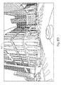
- FIG. 3C is an overhead schematic showing multi-angle points-of-view distributed throughout a neighborhood surrounding a selected object-of-interest
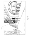
- FIG. 3D is a schematic where the selected object-of-interest is a tall building in a visually crowded neighborhood
- FIG. 4 is a schematic of an exemplary system for collecting images into an image dataset and for post-processing the image dataset to produce multi-angle views of an object-of-interest;
- FIG. 5 is a flowchart of an exemplary method for producing multi-angle views of an object-of-interest
- FIG. 6 is an overhead schematic of the same neighborhood as shown in FIG. 3C showing how images are captured to produce multi-angle points-of-view of a selected object-of-interest, according to aspects of the present invention
- FIGS. 7A through 7E are views of a street locality as seen from multiple locations but all directed toward the same object-of-interest;
- FIGS. 8A through 8E are views of the same street locality and same image dataset as in FIGS. 7A through 7E , but, according to aspects of the present invention, the views are directed toward a different object-of-interest;
- FIG. 9 is a schematic of an exemplary end-user computing platform that presents to a user multi-angle views of his selected object-of-interest.
- FIGS. 1A through 1F together illustrate the use of multi-angle views of an object-of-interest.
- a user may be an architect interested in studying the visual impact of a building on its surrounding neighborhood.
- the user specifies the location of the building as his object-of-interest 100 .
- the user runs an application that allows him to virtually navigate throughout the neighborhood of the object-of-interest 100 .
- the application uses images of the neighborhood taken from an image dataset.
- the images are processed, if necessary, to present a view from the user's current location (the “viewpoint”) looking toward the object-of-interest 100 .
- the object-of-interest 100 is ahead and to the right of the user's current viewpoint.
- the user navigates down the street so that the viewpoint in each figure is a little farther down the street than the viewpoint in the previous figure.
- the view presented to the user is that taken from the location of the current viewpoint looking toward the selected object-of-interest 100 .
- the viewpoint is directly across the street from the object-of-interest 100 which is here clearly seen to be the facade of a museum.
- FIGS. 1A through 1F shows multi-angle views taken in a linear progression down one street
- the user navigates by moving his viewpoint in any direction (including up and down).
- the resulting views are presented as a video continuously, or nearly continuously, looking toward the object-of-interest 100 .
- the user (or another user) can select a new object-of-interest and run through the above process again.
- the images from the image dataset are processed so that the views presented to the user are continuously, or nearly continuously, directed toward the new object-of-interest.
- Some embodiments allow the user to add a virtual object and to specify its location in the neighborhood represented by the image dataset. The user then selects the location of the virtual object as his object-of-interest and runs through the above process. For example, the user adds a virtual street sign and then navigates through the neighborhood to test whether the sign is sufficiently visible from multiple viewpoints.
- FIGS. 2A and 2B illustrate an exemplary system for populating an image dataset to be used by an application presenting multi-angle views of an object-of-interest.
- this system can be used to provide the images used to create the views of FIGS. 1A through 1F .
- the system in these figures collects images of a locality in the real world.
- a vehicle 200 is driving down a road 202 .
- the vehicle 200 includes an image-capture system 204 .
- the image-capture system 204 may include multiple cameras taking overlapping still images or video of both sides of the road 202 .
- the images or video are in a suitable format, such as *.jpg, *.mpg, *.avi, *.bmp, *.mov, etc.
- the vehicle 200 also includes a system for determining its present location, such as a GPS receiver. As the vehicle 200 proceeds down the road 202 , the captured images are stored and are associated with the geographical location at which each picture was taken.
- the image-capture system 204 includes a range-finding device, such as LIDAR.
- the image-capture system 204 and the range-finding device are “registered” so that the distance from the image-capture system 204 to whatever it is viewing is detected and recorded.
- a portion of a captured image (such as every pixel or a group of pixels) is associated with the distance from the image-capture system 204 to the object in the portion of the image.
- a range-finding device is combined with the vehicle's location-determination system (e.g., GPS), the precise real-world geographic location of every pixel is known. When stored with this location information, the resulting pixels are called “3D pixels.”
- the image-capture system 204 can include multiple cameras, or a single camera with multiple lenses. As the vehicle 200 drives down the road 202 , the cameras capture images of various areas of the building 208 . 206 is the point-of-view of a forward-facing camera. In FIG. 2A , this camera is capturing an image of a doorway 210 of the building 208 . At the same time, the point-of-view 212 of a sideways-facing camera includes a signpost 214 located in front of the building 208 .
- each camera in the image-capture system 204 maintains a fixed orientation with respect to the vehicle 200 . In other embodiments, the cameras pan as the vehicle 200 moves.)
- the images captured by the system of FIGS. 2A and 2B are stored in an image dataset.
- FIGS. 3A through 3D the image dataset populated by the system of FIGS. 2A and 2B may not be sufficient, without further processing, to provide multi-angle views of a selected object-of-interest.
- FIGS. 3A through 3D This issue is illustrated by FIGS. 3A through 3D .
- a user has selected as his object-of-interest the doorway 210 of the building 208 .
- the user runs an application to virtually navigate his viewpoint down the street 202 .
- the view presented to the user should be directed toward the doorway 210 , as illustrated by the exemplary viewpoints 300 .
- no image was captured by the system 204 of FIGS. 2A and 2B .
- the topmost view 300 of FIG. 3A looks backward to the doorway 210 , but the exemplary image-capture system 204 of FIGS. 2A and 2B does not include a backward-facing camera.
- multi-angle views can be created by constantly aiming a camera toward the doorway 210 as the image-capture system 204 is moved down the road 202 .
- this requires that the object-of-interest be known in advance, before the images are captured.
- the effort expended when creating the multi-angle views directed toward the doorway 210 as an object-of-interest are of no use when another object-of-interest is selected. For example, in FIG. 3B another user has chosen the street sign 214 as his object-of-interest.
- another image-capture pass would have to be made down the street 202 to create multi-angles views of this second object-of-interest.
- FIGS. 3A and 3B are simplified in order to clearly portray some of the issues involved in creating multi-angle views.
- FIG. 3C more realistically portrays the multi-angle views that a user wants.
- the user wants more than a set of views taken along a single street.
- FIG. 3C shows an exemplary set of viewpoints 300 taken from positions distributed throughout the neighborhood surrounding the selected object-of-interest.
- a prior-art system would require multiple dedicated image-capture passes down all the streets of the neighborhood.
- FIG. 3D illustrates another scenario beyond the scope of prior-art systems.
- the selected object-of-interest is a tall building 302 standing in a visually crowded neighborhood.
- the user wants multi-angle views taken from positions all over the neighborhood.
- the intervening buildings introduce a new problem. From a viewpoint 304 located at the base of the building 302 , the building 302 is unobstructed, but the height of the building 302 means that only the lower portion of the building 302 is visible. From viewpoints such as 306 farther from the base of the building 302 , the top of the building 302 is clearly visible, but an intervening structure 308 blocks the view of the lower portion of the building 302 .
- the user wants to see, from multiple angles, views of the entire building 302 .
- the prior art even using a series of dedicated image-capture passes, does not present to the user the complete multi-angle views that are required.
- FIG. 4 An exemplary system for storing and then processing captured images is presented in FIG. 4 .
- FIG. 5 An exemplary method for using this system is illustrated in FIG. 5 .
- the image-capture system 204 of FIGS. 2A and 2B delivers its images to an image dataset 400 .
- the image dataset 400 is stored on any of a number of computer-readable media. For example, it may be stored on one or more hard drives at one or more locations.
- portions of the image dataset 400 can be loaded into a computer's RAM or ROM.
- the image dataset 400 is transformed or processed as disclosed, the resulting product is stored on the same computer-readable medium or on another one.
- the image dataset 400 in whole or in part, may be distributed to users on a tangible medium, such as a CD, or may be transmitted over a network such as the Internet or over a wireless link to a user's mobile system.
- the image-based navigation application 402 allows a user to virtually move around the neighborhood represented by the image dataset 400 .
- the user specifies the location of an object-of-interest.
- Step 500 of FIG. 5 As the user virtually navigates through the neighborhood, the user's virtual location is noted and passed on to the view producer 406 .
- the view producer 406 reads images from the image dataset 400 (step 504 ) and transforms them to create a view looking from the user's current virtual location to the selected object-of-interest (step 506 ).
- the view producer 406 takes views that are close to the desired view and interpolates or “stitches” them together, using techniques such as those disclosed in Ser. No. 11/796,789, to present a seamless view toward the object-of-interest.
- the view producer 406 can read images captured in multiple passes down multiple streets in the neighborhood and stitch them together.
- the created view is then presented to the user on a display device 408 (or stored on a computer-readable medium). (Step 508 .) This process is repeated as the user virtually moves around and changes his viewpoint.
- FIGS. 6 through 8 illustrate some of the results achievable by the system of FIGS. 4 and 5 .
- FIG. 6 shows the same neighborhood as in FIG. 3C .
- an image-capture system 204 makes a pass through the neighborhood, it repeatedly captures a panorama of the scene around it using a multi-lens camera. This is illustrated in FIG. 6 by the small arrows pointing in several directions from the image-capture locations 600 .
- the discrete locations 600 in FIG. 6 are illustrative: In some embodiments, the image-capture process is continuous.
- These captured images are stored in an image dataset 400 .
- the images in the image dataset 400 are processed to produce views looking toward the object-of-interest.
- the processed view at each virtual location 600 is represented by the large arrow directed toward the selected object-of-interest.
- the camera in the image-capture system 204 has a fixed orientation, the result produced for the user is that of a camera rotating to point toward the selected object-of-interest. As all of the images gathered in the neighborhood are available for processing, views from essentially any location toward any selected object-of-interest can be produced without requiring additional image-capture passes.
- FIGS. 7 and 8 together illustrate the flexibility of aspects of the disclosed embodiments in processing images taken in the same image-capture pass to produce multi-angle views of different objects-of-interest.
- images were captured in multiple directions during a pass down a city street.
- a first object-of-interest 700 was selected: It is on a corner on the left side of the street.
- the captured images were processed to produce the series of multi-angle views 7 A through 7 E looking toward the selected object-of-interest 700 as the user's virtual viewpoint progresses down the street.
- a second object-of-interest 800 was selected: It is a window of a building on the right side of the street.
- FIG. 8E looking back, shows both the first 700 and the second 800 objects-of-interest.
- the user's virtual viewpoint includes a specification of time as well as of geographic location. (Step 502 .) If the image dataset 400 contains the requisite information, then the user can view the object-of-interest through time (e.g., as the seasons progress) as well as across space.
- the images in the image dataset 400 are often taken from public streets, they may include people, vehicles, and other transient objects that would be of no use to a user wishing to view his object-of-interest. Furthermore, objects (e.g., trees or the intervening structure 308 in FIG. 3D ) may obscure the object-of-interest. Also, for privacy concerns, it may be desired to remove or to blur views of pedestrians. Ser. No. 11/980,033 teaches techniques useful for removing these visual objects before the created multi-angle views are presented to the user. (This processing is an optional part of step 506 of FIG. 5 .) The following is a summary of aspects of Ser. No. 11/980,033.
- the system in FIG. 4 optionally includes an object evaluator 410 .
- the evaluator 410 reviews the visual objects represented by data in the image dataset 400 and determines which, if any, of these objects are of concern. The chosen objects are then removed or otherwise de-emphasized (e.g., made semi-transparent) by the object replacer 412 . If removal of a visual object leaves a “visual hole,” then several techniques can be applied by the object replacer 412 to fill this visual hole. For example, data from other images are used, after processing for the different angles of view of the images. Using the scenario of FIG. 3D as an illustration, an image taken from the viewpoint 304 can be combined with an image taken from the viewpoint 306 to present an unobstructed view of the object-of-interest 302 . In some cases, it may be necessary to use information surrounding the visual hole as texture to fill in the hole.
- the virtual-object adder 414 is useful when the object-of-interest does not actually exist in the images in the image dataset 400 .
- a virtual landscaping application can add objects such as flower planters and trees to the street scene to assess their aesthetic appeal. Signs, bus stops, and other functional elements can be added, and their utility tested (e.g., whether a street sign visible from a sufficient distance and through a sufficient angle of view).
- the multi-angle views can be accessed from a device such as the exemplary computing platform 900 shown in FIG. 9 .
- This platform 900 runs one or more applications 902 including, for example, the image-based navigation application 402 as discussed above.
- the user navigates using tools provided by an interface 906 (such as a keyboard, mouse, microphone, voice recognition software, and the like).
- the application 402 produces multi-angle views based on information from the image dataset 400 and displays the views on the display 908 of the user's interface 906 .
- Some embodiments of the computing platform 900 include access to a geographic information database 904 .
- the platform 900 can provide navigation-related applications 902 such as route calculation, route guidance, destination selection, electronic yellow pages, vehicle positioning, and map display. Other applications 902 are also possible.
- This geographic database 904 can include data about the geographic area in which a user is located.
- the geographic database 904 includes data about the roads in the geographic area, including data indicating the locations of the roads and intersections.
- the geographic database 904 may also include information about the names of the roads, one-way streets, number of lanes, locations of traffic signals and signs, speed limits, turn restrictions, address ranges, and so on.
- the geographic database 904 may also include information about objects of interest, such as businesses, landmarks, museums, ATMs, government offices, and so on.
- the data in the geographic database 904 are in a format that is optimized for providing navigation-related functions.
- applications 902 have access to information from a positioning system 910 , such as a GPS device.
- a positioning system 910 such as a GPS device.
- the positioning system 910 may include inertial sensors, differential wheel-speed sensors, a compass, or other equipment that facilitates determining the position of the user.
- the position may be determined as geographic coordinates (latitude, longitude, and altitude), street address, or in any other way.
- the computing platform 900 is a combination of hardware, software, and data.
- the platform 900 can be installed in a vehicle 912 as an in-vehicle navigation system but may also be installed on a special-purpose, handheld navigation device, on a personal digital assistant, on a personal computer, or on a mobile telephone supporting a navigation application.
- the computing platform 900 may be a standalone platform in which the hardware, software, and data are all located locally.
- the computing platform 900 may be connected to a network, e.g., the Internet or a wireless network.
- the image dataset 400 and the geographic database 904 are located remotely from the computing platform 900 and are accessed via the network.
- the image dataset 400 and database 904 are local to the computing platform 900 , but updates are received over the network.
- Some applications 902 can also be provided, in whole or in part, over the network.
Abstract
Disclosed are a system and method for creating multi-angle views of an object-of-interest from images stored in a dataset. A user specifies the location of an object-of-interest. As the user virtually navigates through the locality represented by the image dataset, his current virtual position is determined. Using the user's virtual position and the location of the object-of-interest, images in the image dataset are selected and interpolated or stitched together, if necessary, to present to the user a view from his current virtual position looking toward the object-of-interest. The object-of-interest remains in the view no matter where the user virtually travels. From the same image dataset, another user can select a different object-of-interest and virtually navigate in a similar manner, with his own object-of-interest always in view. The object-of-interest also can be “virtual,” added by computer-animation techniques to the image dataset. For some image datasets, the user can virtually navigate through time as well as through space.
Description
This application is a continuation under 35 U.S.C §120 and 37 CRF §1.53(b) of U.S. patent application Ser. No. 13/954,612 filed Jul. 3, 2013, which is a continuation of Ser. No. 12/002,746 filed Dec. 18, 2007, the disclosures of both are incorporated herein by reference in their entirety.
The present invention is related generally to collections of images, and, more particularly, to processing images to produce views of an object-of-interest.
Image-based navigation has become popular. In one type of system, a computer displays to a user photographic images taken in a real-world locality. The user navigates through a representation of the depicted locality by changing his virtual location or by “turning his head.” The computer keeps up with the user's navigation and displays photographic images taken from the real-world locality that represent the user's current point of view. Thus, the user is given a virtual, visual tour of the real-world locality. One system for performing this kind of feature is disclosed in U.S. patent application Ser. No. 11/796,789, filed on Apr. 30, 2007, the entire disclosure of which is incorporated by reference herein.
An image dataset may lie behind the navigation application. The images used for this application are collected by a set of one or more cameras carried through the locality. The camera may be mounted on a vehicle or carried by a person on foot. The cameras take pictures (or video) in all directions as the vehicle or person moves. Because numerous, overlapping pictures are taken from several points of view, the set of pictures can be post-processed to create seamless 360-degree images, as disclosed in Ser. No. 11/796,789. These images are correlated with real-world geography, for example by gathering GPS data at the same time as the pictures are taken.
Sometimes a user's attention is drawn to one particular “object-of-interest” when he navigates the locality depicted in an image dataset. For example, the user may be an architect assessing the visual impact of a structure (already in place or only planned) on the neighborhood. To help the user view his object-of-interest from as many angles as possible, a “multi-angle object-of-interest video” can be created. This video is created by traveling around the neighborhood while training a video camera on the object-of-interest. (If the structure is only virtual, then the camera is focused on the proposed location of the structure. Afterwards, known computer-animation techniques are used to insert the proposed structure into the video.) This type of video requires a good deal of time and expertise to create and, once created, the resulting video is inflexible and is applicable only to the object-of-interest specified before the video was made.
The above considerations, and others, are addressed by the present invention, which can be understood by referring to the specification, drawings, and claims. According to aspects of the present invention, multi-angle views of an object-of-interest are created from existing images stored in an image dataset. In some embodiments, a user specifies the geographic location of an object-of-interest. The user then virtually navigates through the locality represented by the image dataset. As he navigates, his current virtual position is determined. Using the user's current virtual position and the location of the object-of-interest, images in the image dataset are selected and interpolated or stitched together, if necessary, to present to the user a view from his current virtual position looking toward the object-of-interest. The object-of-interest remains in the view no matter where the user virtual travels.
From the same image dataset, another user can select a different object-of-interest and virtually navigate in a similar manner, with his own object-of-interest continuously (or nearly continuously) in view. Embodiments of the present invention do not require that additional images be collected to create the multi-angle views, neither need the object-of-interest be specified before the image dataset is populated.
Various embodiments employ several techniques, separately or together, when populating an image dataset so that it can provide multiple views of an object-of-interest. The images in the dataset can be “registered,” that is, when the images are collected, the objects in the images are associated with their geographic locations. For example, a GPS unit on the camera tells where the camera was located when an image was taken and the direction in which the camera was facing. A range-finding device (e.g., LIDAR) tells how far away an object in the image is from the location of the camera.
Some of the views presented to the user may include objects that occlude other objects, including the object-of-interest. To enhance the views of the object-of-interest, these occluding objects may be removed or de-emphasized using techniques described in U.S. patent application Ser. No. 11/980,033, filed on Oct. 30, 2007, the entire disclosure of which is incorporated by reference herein.
In some embodiments, the object-of-interest need not actually exist in the images in the dataset. Instead, computer-animation techniques are used to add a “virtual” object-of-interest at a specified location. The above process is then followed to prepare the multi-angle views.
In some embodiments, the user can virtually navigate through time as well as through space. Here, the views presented to the user, continuously (or nearly continuously) in the direction of the selected object-of-interest, can show, for example, the change of seasons or the development of a structure through time.
While the appended claims set forth the features of the present invention with particularity, the invention, together with its objects and advantages, may be best understood from the following detailed description taken in conjunction with the accompanying drawings of which:
Turning to the drawings, wherein like reference numerals refer to like elements, the invention is illustrated as being implemented in a suitable environment. The following description is based on embodiments of the invention and should not be taken as limiting the invention with regard to alternative embodiments that are not explicitly described herein.
In the street scene of FIG. 1A , the object-of-interest 100 is ahead and to the right of the user's current viewpoint. Progressing from FIG. 1A to FIG. 1F , the user navigates down the street so that the viewpoint in each figure is a little farther down the street than the viewpoint in the previous figure. In each figure, the view presented to the user is that taken from the location of the current viewpoint looking toward the selected object-of-interest 100. At FIG. 1D , the viewpoint is directly across the street from the object-of-interest 100 which is here clearly seen to be the facade of a museum.
While the example of FIGS. 1A through 1F shows multi-angle views taken in a linear progression down one street, in some embodiments the user navigates by moving his viewpoint in any direction (including up and down). By processing the user's viewpoint-navigation choices quickly, the resulting views are presented as a video continuously, or nearly continuously, looking toward the object-of-interest 100.
The user (or another user) can select a new object-of-interest and run through the above process again. The images from the image dataset are processed so that the views presented to the user are continuously, or nearly continuously, directed toward the new object-of-interest.
Some embodiments allow the user to add a virtual object and to specify its location in the neighborhood represented by the image dataset. The user then selects the location of the virtual object as his object-of-interest and runs through the above process. For example, the user adds a virtual street sign and then navigates through the neighborhood to test whether the sign is sufficiently visible from multiple viewpoints.
In some implementations, the image-capture system 204 includes a range-finding device, such as LIDAR. The image-capture system 204 and the range-finding device are “registered” so that the distance from the image-capture system 204 to whatever it is viewing is detected and recorded. With such a system, a portion of a captured image (such as every pixel or a group of pixels) is associated with the distance from the image-capture system 204 to the object in the portion of the image. When a range-finding device is combined with the vehicle's location-determination system (e.g., GPS), the precise real-world geographic location of every pixel is known. When stored with this location information, the resulting pixels are called “3D pixels.”
The image-capture system 204 can include multiple cameras, or a single camera with multiple lenses. As the vehicle 200 drives down the road 202, the cameras capture images of various areas of the building 208. 206 is the point-of-view of a forward-facing camera. In FIG. 2A , this camera is capturing an image of a doorway 210 of the building 208. At the same time, the point-of-view 212 of a sideways-facing camera includes a signpost 214 located in front of the building 208.
As the vehicle 200 proceeds down the road 202, areas of the building 208 originally imaged by one camera are now imaged again by other cameras (or by the same camera from another vantage point). For example, in FIG. 2B the doorway 210 is now imaged by the sideways-facing camera with the point-of-view 212. (In many embodiments, each camera in the image-capture system 204 maintains a fixed orientation with respect to the vehicle 200. In other embodiments, the cameras pan as the vehicle 200 moves.) The images captured by the system of FIGS. 2A and 2B are stored in an image dataset.
However, the image dataset populated by the system of FIGS. 2A and 2B may not be sufficient, without further processing, to provide multi-angle views of a selected object-of-interest. This issue is illustrated by FIGS. 3A through 3D . In FIG. 3A , a user has selected as his object-of-interest the doorway 210 of the building 208. The user runs an application to virtually navigate his viewpoint down the street 202. At each point on the street 202, the view presented to the user should be directed toward the doorway 210, as illustrated by the exemplary viewpoints 300. From several of these viewpoints 300, however, no image was captured by the system 204 of FIGS. 2A and 2B . For example, the topmost view 300 of FIG. 3A looks backward to the doorway 210, but the exemplary image-capture system 204 of FIGS. 2A and 2B does not include a backward-facing camera.
In the prior art, multi-angle views can be created by constantly aiming a camera toward the doorway 210 as the image-capture system 204 is moved down the road 202. However, this requires that the object-of-interest be known in advance, before the images are captured. Also, the effort expended when creating the multi-angle views directed toward the doorway 210 as an object-of-interest are of no use when another object-of-interest is selected. For example, in FIG. 3B another user has chosen the street sign 214 as his object-of-interest. Using the prior art, another image-capture pass would have to be made down the street 202 to create multi-angles views of this second object-of-interest.
The examples in FIGS. 3A and 3B are simplified in order to clearly portray some of the issues involved in creating multi-angle views. For some situations, FIG. 3C more realistically portrays the multi-angle views that a user wants. Here, the user wants more than a set of views taken along a single street. FIG. 3C shows an exemplary set of viewpoints 300 taken from positions distributed throughout the neighborhood surrounding the selected object-of-interest. To collect all of the multi-angle views of FIG. 3C , a prior-art system would require multiple dedicated image-capture passes down all the streets of the neighborhood.
As a final example, FIG. 3D illustrates another scenario beyond the scope of prior-art systems. The selected object-of-interest is a tall building 302 standing in a visually crowded neighborhood. As in the scenario of FIG. 3C , the user wants multi-angle views taken from positions all over the neighborhood. However, the intervening buildings introduce a new problem. From a viewpoint 304 located at the base of the building 302, the building 302 is unobstructed, but the height of the building 302 means that only the lower portion of the building 302 is visible. From viewpoints such as 306 farther from the base of the building 302, the top of the building 302 is clearly visible, but an intervening structure 308 blocks the view of the lower portion of the building 302. The user wants to see, from multiple angles, views of the entire building 302. The prior art, even using a series of dedicated image-capture passes, does not present to the user the complete multi-angle views that are required.
Aspects of the present invention, as described below, alleviate the need for a dedicated image-gathering pass for each object-of-interest and address the other issues discussed above.
An exemplary system for storing and then processing captured images is presented in FIG. 4 . An exemplary method for using this system is illustrated in FIG. 5 . The image-capture system 204 of FIGS. 2A and 2B delivers its images to an image dataset 400. The image dataset 400 is stored on any of a number of computer-readable media. For example, it may be stored on one or more hard drives at one or more locations. During use and processing, portions of the image dataset 400 can be loaded into a computer's RAM or ROM. When the image dataset 400 is transformed or processed as disclosed, the resulting product is stored on the same computer-readable medium or on another one. The image dataset 400, in whole or in part, may be distributed to users on a tangible medium, such as a CD, or may be transmitted over a network such as the Internet or over a wireless link to a user's mobile system.
The image-based navigation application 402 allows a user to virtually move around the neighborhood represented by the image dataset 400. With an input device 404, the user specifies the location of an object-of-interest. (Step 500 of FIG. 5 .) As the user virtually navigates through the neighborhood, the user's virtual location is noted and passed on to the view producer 406. (Step 502.) The view producer 406 reads images from the image dataset 400 (step 504) and transforms them to create a view looking from the user's current virtual location to the selected object-of-interest (step 506). If the image dataset 400 does not include an image taken from the current virtual viewpoint and directed toward the selected object-of-interest, then the view producer 406 takes views that are close to the desired view and interpolates or “stitches” them together, using techniques such as those disclosed in Ser. No. 11/796,789, to present a seamless view toward the object-of-interest. To present views from positions taken throughout a neighborhood, the view producer 406 can read images captured in multiple passes down multiple streets in the neighborhood and stitch them together. The created view is then presented to the user on a display device 408 (or stored on a computer-readable medium). (Step 508.) This process is repeated as the user virtually moves around and changes his viewpoint.
In some embodiments, the user's virtual viewpoint includes a specification of time as well as of geographic location. (Step 502.) If the image dataset 400 contains the requisite information, then the user can view the object-of-interest through time (e.g., as the seasons progress) as well as across space.
Because the images in the image dataset 400 are often taken from public streets, they may include people, vehicles, and other transient objects that would be of no use to a user wishing to view his object-of-interest. Furthermore, objects (e.g., trees or the intervening structure 308 in FIG. 3D ) may obscure the object-of-interest. Also, for privacy concerns, it may be desired to remove or to blur views of pedestrians. Ser. No. 11/980,033 teaches techniques useful for removing these visual objects before the created multi-angle views are presented to the user. (This processing is an optional part of step 506 of FIG. 5 .) The following is a summary of aspects of Ser. No. 11/980,033. The system in FIG. 4 optionally includes an object evaluator 410. The evaluator 410 reviews the visual objects represented by data in the image dataset 400 and determines which, if any, of these objects are of concern. The chosen objects are then removed or otherwise de-emphasized (e.g., made semi-transparent) by the object replacer 412. If removal of a visual object leaves a “visual hole,” then several techniques can be applied by the object replacer 412 to fill this visual hole. For example, data from other images are used, after processing for the different angles of view of the images. Using the scenario of FIG. 3D as an illustration, an image taken from the viewpoint 304 can be combined with an image taken from the viewpoint 306 to present an unobstructed view of the object-of-interest 302. In some cases, it may be necessary to use information surrounding the visual hole as texture to fill in the hole.
The virtual-object adder 414 is useful when the object-of-interest does not actually exist in the images in the image dataset 400. For example, a virtual landscaping application can add objects such as flower planters and trees to the street scene to assess their aesthetic appeal. Signs, bus stops, and other functional elements can be added, and their utility tested (e.g., whether a street sign visible from a sufficient distance and through a sufficient angle of view).
The multi-angle views can be accessed from a device such as the exemplary computing platform 900 shown in FIG. 9 . This platform 900 runs one or more applications 902 including, for example, the image-based navigation application 402 as discussed above. For this application 402, the user navigates using tools provided by an interface 906 (such as a keyboard, mouse, microphone, voice recognition software, and the like). In response, the application 402 produces multi-angle views based on information from the image dataset 400 and displays the views on the display 908 of the user's interface 906.
Some embodiments of the computing platform 900 include access to a geographic information database 904. Using this database 904, the platform 900 can provide navigation-related applications 902 such as route calculation, route guidance, destination selection, electronic yellow pages, vehicle positioning, and map display. Other applications 902 are also possible. This geographic database 904 can include data about the geographic area in which a user is located. In some embodiments, the geographic database 904 includes data about the roads in the geographic area, including data indicating the locations of the roads and intersections. The geographic database 904 may also include information about the names of the roads, one-way streets, number of lanes, locations of traffic signals and signs, speed limits, turn restrictions, address ranges, and so on. The geographic database 904 may also include information about objects of interest, such as businesses, landmarks, museums, ATMs, government offices, and so on. In some embodiments, the data in the geographic database 904 are in a format that is optimized for providing navigation-related functions.
In some embodiments, applications 902 have access to information from a positioning system 910, such as a GPS device. If the computing platform is in a vehicle, such as vehicle 912, the positioning system 910 may include inertial sensors, differential wheel-speed sensors, a compass, or other equipment that facilitates determining the position of the user. The position may be determined as geographic coordinates (latitude, longitude, and altitude), street address, or in any other way.
In some embodiments, the computing platform 900 is a combination of hardware, software, and data. The platform 900 can be installed in a vehicle 912 as an in-vehicle navigation system but may also be installed on a special-purpose, handheld navigation device, on a personal digital assistant, on a personal computer, or on a mobile telephone supporting a navigation application. The computing platform 900 may be a standalone platform in which the hardware, software, and data are all located locally. Alternatively, the computing platform 900 may be connected to a network, e.g., the Internet or a wireless network. In some embodiments, the image dataset 400 and the geographic database 904 are located remotely from the computing platform 900 and are accessed via the network. In some embodiments, the image dataset 400 and database 904 are local to the computing platform 900, but updates are received over the network. Some applications 902 can also be provided, in whole or in part, over the network.
In view of the many possible embodiments to which the principles of this invention may be applied, it should be recognized that the embodiments described herein with respect to the drawing figures are meant to be illustrative only and should not be taken as limiting the scope of the invention. For example, embodiments in some environments may take advantage of other image-capture systems or may support end-user applications other than those illustrated. Therefore, the invention as described herein contemplates all such embodiments as may come within the scope of the following claims and equivalents thereof.
Claims (20)
1. A method comprising:
receiving an image collected by a camera, wherein the image includes a plurality of pixels; receiving distance data from a range-finding device; registering the plurality of pixels of the image data with the distance data; identifying, using a processor, a first location for a viewpoint; adding a virtual object-of-interest to the image, wherein the virtual object-of-interest is added as a part of a landscape represented by the image; identifying, using the processor, a second location for the virtual object-of-interest in the image; and determining, using the processor, a view of the virtual object-of-interest from the first location toward the second location to test for the utility of the virtual object-of-interest to determine if it is visible from a distance and at an angle of view associated with the first location with respect to the second location.
2. The method of claim 1 , wherein the virtual object-of-interest is a geographic indicator.
3. The method of claim 2 , wherein the geographic indicator is a virtual street sign that includes a road name, a number of lanes, a location of a traffic signal or sign, a speed limit, or a turn restriction.
4. The method of claim 1 , further comprising:
receiving a third location for a viewpoint; and
modifying the view of the virtual object-of-interest to be from the third location toward the second location.
5. The method of claim 1 , wherein the first location is a current location of a mobile device.
6. The method of claim 1 , further comprising:
analyzing the image for an object of concern; and
modifying the object of concern.
7. The method of claim 6 , wherein at least a portion of the object of concern is replaced by the virtual object-of-interest.
8. The method of claim 1 , further comprising:
sending the view to a mobile device.
9. The method of claim 1 , wherein registering the plurality of pixels of the image data with the distance data comprises:
receiving a geographic location where the image was collected; and
assigning three-dimensional locations to the plurality of pixels using the geographic location where the image was collected and the distance data.
10. An apparatus comprising:
a memory configured to store an image collected by a camera, wherein the image includes a plurality of pixels, and to store distance data collected by a range-finding device; and
a processor configured to register the plurality of pixels of the image data with the distance data, to add a virtual object to the image at a user specified location, and to generate a view from a first location toward a second location associated with the user specified location of the virtual object,
wherein the virtual object is added to as part of the scene captured in the image to test the utility of the object-of-interest by determining if the virtual object-of-interest is visible from different distances and different angles of view.
11. The apparatus of claim 10 , wherein the virtual object is a geographic indicator.
12. The apparatus of claim 11 , wherein the geographic indicator is a virtual street sign that includes a road name, a number of lanes, a location of a traffic signal or sign, a speed limit, or a turn restriction.
13. The apparatus of claim 10 , wherein the processor is configured to modify the view to be from a third location toward the second location, wherein the third location is received from a mobile device.
14. The apparatus of claim 11 , wherein the third location is a current location of the mobile device.
15. A non-transitory computer-readable medium containing computer-executable instructions for performing a method comprising:
accessing an image collected by a camera, wherein the image includes a plurality of pixels and a virtual object added by a user within the image, the virtual object added to a street scene represented by the image;
accessing distance data collected by a range-finding device;
assigning three-dimensional locations to the plurality of pixels based on the distance data;
identifying, using a processor, a first location for a viewpoint;
identifying, using the processor, a second location for the virtual object in the image; and
generating, using the processor, a modified image with the viewpoint from the first location and facing toward the second location, the modified image generated to assess the utility of the of the virtual object added in the street scene from the distance and angle of view from the first location to the second location.
16. The non-transitory computer-readable medium of claim 15 , wherein the virtual object is a geographic indicator.
17. The non-transitory computer-readable medium of claim 16 , wherein the geographic indicator includes a road characteristic.
18. The non-transitory computer-readable medium of claim 16 , wherein the geographic indicator includes a location of a traffic signal or sign.
19. The non-transitory computer-readable medium of claim 15 , wherein the virtual object is a landscape object.
20. The non-transitory computer-readable medium of claim 19 , wherein the landscape object comprises flowers, trees, planters or a combination thereof.
Priority Applications (1)
| Application Number | Priority Date | Filing Date | Title |
|---|---|---|---|
| US14/972,894 US9858717B2 (en) | 2007-12-18 | 2015-12-17 | System and method for producing multi-angle views of an object-of-interest from images in an image dataset |
Applications Claiming Priority (3)
| Application Number | Priority Date | Filing Date | Title |
|---|---|---|---|
| US12/002,746 US8531449B2 (en) | 2007-12-18 | 2007-12-18 | System and method for producing multi-angle views of an object-of-interest from images in an image dataset |
| US13/954,612 US9251174B2 (en) | 2007-12-18 | 2013-07-30 | System and method for producing multi-angle views of an object-of-interest from images in an image dataset |
| US14/972,894 US9858717B2 (en) | 2007-12-18 | 2015-12-17 | System and method for producing multi-angle views of an object-of-interest from images in an image dataset |
Related Parent Applications (1)
| Application Number | Title | Priority Date | Filing Date |
|---|---|---|---|
| US13/954,612 Continuation US9251174B2 (en) | 2007-12-18 | 2013-07-30 | System and method for producing multi-angle views of an object-of-interest from images in an image dataset |
Publications (2)
| Publication Number | Publication Date |
|---|---|
| US20160110918A1 US20160110918A1 (en) | 2016-04-21 |
| US9858717B2 true US9858717B2 (en) | 2018-01-02 |
Family
ID=40752592
Family Applications (3)
| Application Number | Title | Priority Date | Filing Date |
|---|---|---|---|
| US12/002,746 Active 2030-07-15 US8531449B2 (en) | 2007-12-18 | 2007-12-18 | System and method for producing multi-angle views of an object-of-interest from images in an image dataset |
| US13/954,612 Active US9251174B2 (en) | 2007-12-18 | 2013-07-30 | System and method for producing multi-angle views of an object-of-interest from images in an image dataset |
| US14/972,894 Active US9858717B2 (en) | 2007-12-18 | 2015-12-17 | System and method for producing multi-angle views of an object-of-interest from images in an image dataset |
Family Applications Before (2)
| Application Number | Title | Priority Date | Filing Date |
|---|---|---|---|
| US12/002,746 Active 2030-07-15 US8531449B2 (en) | 2007-12-18 | 2007-12-18 | System and method for producing multi-angle views of an object-of-interest from images in an image dataset |
| US13/954,612 Active US9251174B2 (en) | 2007-12-18 | 2013-07-30 | System and method for producing multi-angle views of an object-of-interest from images in an image dataset |
Country Status (1)
| Country | Link |
|---|---|
| US (3) | US8531449B2 (en) |
Cited By (1)
| Publication number | Priority date | Publication date | Assignee | Title |
|---|---|---|---|---|
| US11641108B2 (en) | 2011-03-09 | 2023-05-02 | D&R Tech LLC | Systems, apparatus, and methods for power management |
Families Citing this family (68)
| Publication number | Priority date | Publication date | Assignee | Title |
|---|---|---|---|---|
| US9063633B2 (en) * | 2006-03-30 | 2015-06-23 | Arjuna Indraeswaran Rajasingham | Virtual navigation system for virtual and real spaces |
| US8503763B2 (en) | 2008-01-04 | 2013-08-06 | 3M Innovative Properties Company | Image signatures for use in motion-based three-dimensional reconstruction |
| US20100021013A1 (en) * | 2008-07-25 | 2010-01-28 | Gale William N | Open area maps with guidance |
| US8417446B2 (en) * | 2008-07-25 | 2013-04-09 | Navteq B.V. | Link-node maps based on open area maps |
| US8229176B2 (en) * | 2008-07-25 | 2012-07-24 | Navteq B.V. | End user image open area maps |
| US8825387B2 (en) * | 2008-07-25 | 2014-09-02 | Navteq B.V. | Positioning open area maps |
| US8099237B2 (en) | 2008-07-25 | 2012-01-17 | Navteq North America, Llc | Open area maps |
| US8374780B2 (en) * | 2008-07-25 | 2013-02-12 | Navteq B.V. | Open area maps with restriction content |
| US8339417B2 (en) * | 2008-07-25 | 2012-12-25 | Navteq B.V. | Open area maps based on vector graphics format images |
| US20100023251A1 (en) * | 2008-07-25 | 2010-01-28 | Gale William N | Cost based open area maps |
| US8422825B1 (en) | 2008-11-05 | 2013-04-16 | Hover Inc. | Method and system for geometry extraction, 3D visualization and analysis using arbitrary oblique imagery |
| KR20110052124A (en) * | 2009-11-12 | 2011-05-18 | 삼성전자주식회사 | Method for generating and referencing panorama image and mobile terminal using the same |
| US8566020B2 (en) * | 2009-12-01 | 2013-10-22 | Nokia Corporation | Method and apparatus for transforming three-dimensional map objects to present navigation information |
| US20110144909A1 (en) * | 2009-12-14 | 2011-06-16 | Robert Bosch Gmbh | Personalized and context-sensitive 3d route guidance |
| CN101872492B (en) * | 2010-06-09 | 2012-11-28 | 中国科学院深圳先进技术研究院 | Multi-angle map implementation method of three-dimensional simulation city |
| US8515669B2 (en) * | 2010-06-25 | 2013-08-20 | Microsoft Corporation | Providing an improved view of a location in a spatial environment |
| US8577604B1 (en) * | 2010-07-07 | 2013-11-05 | Google Inc. | System and method of determining map coordinates from images |
| US9900522B2 (en) | 2010-12-01 | 2018-02-20 | Magna Electronics Inc. | System and method of establishing a multi-camera image using pixel remapping |
| US8810598B2 (en) | 2011-04-08 | 2014-08-19 | Nant Holdings Ip, Llc | Interference based augmented reality hosting platforms |
| KR101758164B1 (en) * | 2011-04-08 | 2017-07-26 | 엘지전자 주식회사 | Mobile twrminal and 3d multi-angle view controlling method thereof |
| WO2012147303A1 (en) * | 2011-04-25 | 2012-11-01 | Hayashi Mitsuo | Omnidirectional image editing program and omnidirectional image editing device |
| US10793067B2 (en) | 2011-07-26 | 2020-10-06 | Magna Electronics Inc. | Imaging system for vehicle |
| US9791290B2 (en) | 2012-02-29 | 2017-10-17 | Here Global B.V. | Manipulation of user attention with respect to a simulated field of view for geographic navigation via constrained focus on, perspective attraction to, and/or correction and dynamic adjustment of, points of interest |
| US9024973B2 (en) * | 2012-03-12 | 2015-05-05 | Sony Corporation | Method and arrangement in an electronic device |
| US10163261B2 (en) * | 2014-03-19 | 2018-12-25 | Matterport, Inc. | Selecting two-dimensional imagery data for display within a three-dimensional model |
| US9786097B2 (en) | 2012-06-22 | 2017-10-10 | Matterport, Inc. | Multi-modal method for interacting with 3D models |
| US9256961B2 (en) * | 2012-06-28 | 2016-02-09 | Here Global B.V. | Alternate viewpoint image enhancement |
| US9256983B2 (en) | 2012-06-28 | 2016-02-09 | Here Global B.V. | On demand image overlay |
| US10905391B2 (en) * | 2012-11-23 | 2021-02-02 | Imagia Healthcare Inc. | Method and system for displaying to a user a transition between a first rendered projection and a second rendered projection |
| US9836875B2 (en) * | 2013-04-26 | 2017-12-05 | Flipboard, Inc. | Viewing angle image manipulation based on device rotation |
| EP2818948B1 (en) * | 2013-06-27 | 2016-11-16 | ABB Schweiz AG | Method and data presenting device for assisting a remote user to provide instructions |
| US11670046B2 (en) | 2013-07-23 | 2023-06-06 | Hover Inc. | 3D building analyzer |
| US11721066B2 (en) | 2013-07-23 | 2023-08-08 | Hover Inc. | 3D building model materials auto-populator |
| US9582516B2 (en) | 2013-10-17 | 2017-02-28 | Nant Holdings Ip, Llc | Wide area augmented reality location-based services |
| WO2015061735A1 (en) | 2013-10-25 | 2015-04-30 | Hover Inc. | Estimating dimensions of geo-referenced ground-level imagery using orthogonal imagery |
| US9360338B2 (en) | 2014-07-16 | 2016-06-07 | International Business Machines Corporation | Presenting the viewability of a point of interest on a map |
| US9851299B2 (en) | 2014-10-25 | 2017-12-26 | Isle Management Co. | Method of analyzing air quality |
| US10275935B2 (en) | 2014-10-31 | 2019-04-30 | Fyusion, Inc. | System and method for infinite synthetic image generation from multi-directional structured image array |
| US10127463B2 (en) | 2014-11-21 | 2018-11-13 | Magna Electronics Inc. | Vehicle vision system with multiple cameras |
| US10185463B2 (en) * | 2015-02-13 | 2019-01-22 | Nokia Technologies Oy | Method and apparatus for providing model-centered rotation in a three-dimensional user interface |
| US10698558B2 (en) * | 2015-07-15 | 2020-06-30 | Fyusion, Inc. | Automatic tagging of objects on a multi-view interactive digital media representation of a dynamic entity |
| US10242474B2 (en) | 2015-07-15 | 2019-03-26 | Fyusion, Inc. | Artificially rendering images using viewpoint interpolation and extrapolation |
| US10147211B2 (en) | 2015-07-15 | 2018-12-04 | Fyusion, Inc. | Artificially rendering images using viewpoint interpolation and extrapolation |
| US10750161B2 (en) * | 2015-07-15 | 2020-08-18 | Fyusion, Inc. | Multi-view interactive digital media representation lock screen |
| US11006095B2 (en) | 2015-07-15 | 2021-05-11 | Fyusion, Inc. | Drone based capture of a multi-view interactive digital media |
| US10222932B2 (en) | 2015-07-15 | 2019-03-05 | Fyusion, Inc. | Virtual reality environment based manipulation of multilayered multi-view interactive digital media representations |
| US10852902B2 (en) * | 2015-07-15 | 2020-12-01 | Fyusion, Inc. | Automatic tagging of objects on a multi-view interactive digital media representation of a dynamic entity |
| US11095869B2 (en) | 2015-09-22 | 2021-08-17 | Fyusion, Inc. | System and method for generating combined embedded multi-view interactive digital media representations |
| US11783864B2 (en) | 2015-09-22 | 2023-10-10 | Fyusion, Inc. | Integration of audio into a multi-view interactive digital media representation |
| US9589358B1 (en) | 2015-09-29 | 2017-03-07 | International Business Machines Corporation | Determination of point of interest views from selected vantage points |
| US10187590B2 (en) | 2015-10-27 | 2019-01-22 | Magna Electronics Inc. | Multi-camera vehicle vision system with image gap fill |
| US9934615B2 (en) | 2016-04-06 | 2018-04-03 | Facebook, Inc. | Transition between binocular and monocular views |
| US10257501B2 (en) * | 2016-04-06 | 2019-04-09 | Facebook, Inc. | Efficient canvas view generation from intermediate views |
| US11202017B2 (en) | 2016-10-06 | 2021-12-14 | Fyusion, Inc. | Live style transfer on a mobile device |
| US10452076B2 (en) | 2017-01-04 | 2019-10-22 | Magna Electronics Inc. | Vehicle vision system with adjustable computation and data compression |
| CN107133583A (en) * | 2017-04-27 | 2017-09-05 | 深圳前海弘稼科技有限公司 | One kind plants plant information acquisition method and device |
| US10313651B2 (en) | 2017-05-22 | 2019-06-04 | Fyusion, Inc. | Snapshots at predefined intervals or angles |
| US11069147B2 (en) | 2017-06-26 | 2021-07-20 | Fyusion, Inc. | Modification of multi-view interactive digital media representation |
| US10250953B1 (en) | 2017-11-27 | 2019-04-02 | International Business Machines Corporation | Displaying linked hyper-videos within hyper-videos |
| US11166079B2 (en) | 2017-12-22 | 2021-11-02 | International Business Machines Corporation | Viewport selection for hypervideo presentation |
| US10592747B2 (en) | 2018-04-26 | 2020-03-17 | Fyusion, Inc. | Method and apparatus for 3-D auto tagging |
| CN110673718B (en) | 2018-07-02 | 2021-10-29 | 苹果公司 | Focus-based commissioning and inspection for display systems |
| JP7275556B2 (en) * | 2018-12-14 | 2023-05-18 | トヨタ自動車株式会社 | Information processing system, program, and information processing method |
| US20200286279A1 (en) | 2019-03-07 | 2020-09-10 | Alibaba Group Holding Limited | Method, apparatus, medium, and device for processing multi-angle free-perspective image data |
| US11022961B2 (en) | 2019-04-04 | 2021-06-01 | Plus One Robotics, Inc. | Industrial robotics systems and methods for continuous and automated learning |
| WO2020210769A1 (en) | 2019-04-11 | 2020-10-15 | Plus One Robotics, Inc. | Systems and methods for identifying package properties in an automated industrial robotics system |
| CN110348363B (en) * | 2019-07-05 | 2021-06-15 | 西安邮电大学 | Vehicle tracking method for eliminating similar vehicle interference based on multi-frame angle information fusion |
| US20210274092A1 (en) * | 2020-02-28 | 2021-09-02 | Weta Digital Limited | Reconstruction of obscured views in captured imagery using pixel replacement from secondary imagery |
Citations (23)
| Publication number | Priority date | Publication date | Assignee | Title |
|---|---|---|---|---|
| US5161886A (en) | 1989-01-11 | 1992-11-10 | U.S. Philips Corp. | Method for the perspective display of a part of a topographic map, and device suitable for performing such a method |
| US5774569A (en) | 1994-07-25 | 1998-06-30 | Waldenmaier; H. Eugene W. | Surveillance system |
| US6222583B1 (en) | 1997-03-27 | 2001-04-24 | Nippon Telegraph And Telephone Corporation | Device and system for labeling sight images |
| US6363161B2 (en) | 1998-10-23 | 2002-03-26 | Facet Technology Corp. | System for automatically generating database of objects of interest by analysis of images recorded by moving vehicle |
| US6424273B1 (en) * | 2001-03-30 | 2002-07-23 | Koninklijke Philips Electronics N.V. | System to aid a driver to determine whether to change lanes |
| US20020113791A1 (en) | 2001-01-02 | 2002-08-22 | Jiang Li | Image-based virtual reality player with integrated 3D graphics objects |
| US20030026469A1 (en) | 2001-07-30 | 2003-02-06 | Accuimage Diagnostics Corp. | Methods and systems for combining a plurality of radiographic images |
| US20040090523A1 (en) | 2001-06-27 | 2004-05-13 | Tetsujiro Kondo | Image processing apparatus and method and image pickup apparatus |
| US20040098175A1 (en) | 2002-11-19 | 2004-05-20 | Amir Said | Methods and apparatus for imaging and displaying a navigable path |
| US20050154505A1 (en) * | 2003-12-17 | 2005-07-14 | Koji Nakamura | Vehicle information display system |
| US20060120592A1 (en) | 2004-12-07 | 2006-06-08 | Chang-Joon Park | Apparatus for recovering background in image sequence and method thereof |
| US20060177099A1 (en) * | 2004-12-20 | 2006-08-10 | Ying Zhu | System and method for on-road detection of a vehicle using knowledge fusion |
| US20060269105A1 (en) | 2005-05-24 | 2006-11-30 | Langlinais Ashton L | Methods, Apparatus and Products for Image Capture |
| US7155336B2 (en) | 2004-03-24 | 2006-12-26 | A9.Com, Inc. | System and method for automatically collecting images of objects at geographic locations and displaying same in online directories |
| US7216035B2 (en) | 2002-08-07 | 2007-05-08 | Siemens Aktiengeselschaft | Method and device for displaying navigational information for a vehicle |
| US20070118281A1 (en) | 2005-11-18 | 2007-05-24 | Tomtom International B.V. | navigation device displaying traffic information |
| US7239760B2 (en) | 2000-10-06 | 2007-07-03 | Enrico Di Bernardo | System and method for creating, storing, and utilizing composite images of a geographic location |
| US20070206945A1 (en) | 2006-03-01 | 2007-09-06 | Delorme David M | Method and apparatus for panoramic imaging |
| DE102006010481A1 (en) * | 2006-03-07 | 2007-09-13 | Robert Bosch Gmbh | Method and arrangement for displaying navigation instructions |
| US20080112610A1 (en) | 2006-11-14 | 2008-05-15 | S2, Inc. | System and method for 3d model generation |
| US20080211914A1 (en) | 2005-02-24 | 2008-09-04 | Perceptics, Llc | Apparatus and method for capturing and displaying images of the undercarriage of vehicles |
| US20090110239A1 (en) | 2007-10-30 | 2009-04-30 | Navteq North America, Llc | System and method for revealing occluded objects in an image dataset |
| US7688229B2 (en) | 2007-04-30 | 2010-03-30 | Navteq North America, Llc | System and method for stitching of video for routes |
Family Cites Families (1)
| Publication number | Priority date | Publication date | Assignee | Title |
|---|---|---|---|---|
| WO2005115764A2 (en) * | 2004-05-21 | 2005-12-08 | Esselte | Punching and binding system and elements thereof |
-
2007
- 2007-12-18 US US12/002,746 patent/US8531449B2/en active Active
-
2013
- 2013-07-30 US US13/954,612 patent/US9251174B2/en active Active
-
2015
- 2015-12-17 US US14/972,894 patent/US9858717B2/en active Active
Patent Citations (26)
| Publication number | Priority date | Publication date | Assignee | Title |
|---|---|---|---|---|
| US5161886A (en) | 1989-01-11 | 1992-11-10 | U.S. Philips Corp. | Method for the perspective display of a part of a topographic map, and device suitable for performing such a method |
| US5161886C1 (en) | 1989-01-11 | 2001-10-30 | Philips Corp | Method for the perspective display of a part of a topographic map and device suitable for performing such a method |
| US5774569A (en) | 1994-07-25 | 1998-06-30 | Waldenmaier; H. Eugene W. | Surveillance system |
| US6222583B1 (en) | 1997-03-27 | 2001-04-24 | Nippon Telegraph And Telephone Corporation | Device and system for labeling sight images |
| US6363161B2 (en) | 1998-10-23 | 2002-03-26 | Facet Technology Corp. | System for automatically generating database of objects of interest by analysis of images recorded by moving vehicle |
| US7239760B2 (en) | 2000-10-06 | 2007-07-03 | Enrico Di Bernardo | System and method for creating, storing, and utilizing composite images of a geographic location |
| US20020113791A1 (en) | 2001-01-02 | 2002-08-22 | Jiang Li | Image-based virtual reality player with integrated 3D graphics objects |
| US6424273B1 (en) * | 2001-03-30 | 2002-07-23 | Koninklijke Philips Electronics N.V. | System to aid a driver to determine whether to change lanes |
| US20040090523A1 (en) | 2001-06-27 | 2004-05-13 | Tetsujiro Kondo | Image processing apparatus and method and image pickup apparatus |
| US20030026469A1 (en) | 2001-07-30 | 2003-02-06 | Accuimage Diagnostics Corp. | Methods and systems for combining a plurality of radiographic images |
| US7216035B2 (en) | 2002-08-07 | 2007-05-08 | Siemens Aktiengeselschaft | Method and device for displaying navigational information for a vehicle |
| US20040098175A1 (en) | 2002-11-19 | 2004-05-20 | Amir Said | Methods and apparatus for imaging and displaying a navigable path |
| US20050154505A1 (en) * | 2003-12-17 | 2005-07-14 | Koji Nakamura | Vehicle information display system |
| US7272501B2 (en) | 2004-03-24 | 2007-09-18 | A9.Com, Inc. | System and method for automatically collecting images of objects at geographic locations and displaying same in online directories |
| US7155336B2 (en) | 2004-03-24 | 2006-12-26 | A9.Com, Inc. | System and method for automatically collecting images of objects at geographic locations and displaying same in online directories |
| US20060120592A1 (en) | 2004-12-07 | 2006-06-08 | Chang-Joon Park | Apparatus for recovering background in image sequence and method thereof |
| US20060177099A1 (en) * | 2004-12-20 | 2006-08-10 | Ying Zhu | System and method for on-road detection of a vehicle using knowledge fusion |
| US20080211914A1 (en) | 2005-02-24 | 2008-09-04 | Perceptics, Llc | Apparatus and method for capturing and displaying images of the undercarriage of vehicles |
| US20060269105A1 (en) | 2005-05-24 | 2006-11-30 | Langlinais Ashton L | Methods, Apparatus and Products for Image Capture |
| US20070118281A1 (en) | 2005-11-18 | 2007-05-24 | Tomtom International B.V. | navigation device displaying traffic information |
| US20070206945A1 (en) | 2006-03-01 | 2007-09-06 | Delorme David M | Method and apparatus for panoramic imaging |
| DE102006010481A1 (en) * | 2006-03-07 | 2007-09-13 | Robert Bosch Gmbh | Method and arrangement for displaying navigation instructions |
| US20090187333A1 (en) | 2006-03-07 | 2009-07-23 | Mario Mueller | Method and System for Displaying Navigation Instructions |
| US20080112610A1 (en) | 2006-11-14 | 2008-05-15 | S2, Inc. | System and method for 3d model generation |
| US7688229B2 (en) | 2007-04-30 | 2010-03-30 | Navteq North America, Llc | System and method for stitching of video for routes |
| US20090110239A1 (en) | 2007-10-30 | 2009-04-30 | Navteq North America, Llc | System and method for revealing occluded objects in an image dataset |
Non-Patent Citations (1)
| Title |
|---|
| B. Bell et al., View Management for Virtual and Augmented Reality, Nov. 2001, pp. 101-110, ACM Symp. on User Interface Software and Technology. |
Cited By (1)
| Publication number | Priority date | Publication date | Assignee | Title |
|---|---|---|---|---|
| US11641108B2 (en) | 2011-03-09 | 2023-05-02 | D&R Tech LLC | Systems, apparatus, and methods for power management |
Also Published As
| Publication number | Publication date |
|---|---|
| US9251174B2 (en) | 2016-02-02 |
| US8531449B2 (en) | 2013-09-10 |
| US20160110918A1 (en) | 2016-04-21 |
| US20130318078A1 (en) | 2013-11-28 |
| US20090153549A1 (en) | 2009-06-18 |
Similar Documents
| Publication | Publication Date | Title |
|---|---|---|
| US9858717B2 (en) | System and method for producing multi-angle views of an object-of-interest from images in an image dataset | |
| US8086071B2 (en) | System and method for revealing occluded objects in an image dataset | |
| US8000895B2 (en) | Navigation and inspection system | |
| EP2401703B1 (en) | System and method of indicating transition between street level images | |
| US20100118116A1 (en) | Method of and apparatus for producing a multi-viewpoint panorama | |
| US8532924B2 (en) | Method and apparatus for displaying three-dimensional terrain and route guidance | |
| KR20110044217A (en) | Method of displaying navigation data in 3d | |
| JP2006513407A (en) | Advanced 3D visualization system and method for mobile navigation unit | |
| CA2625105A1 (en) | Method for generating an enhanced map | |
| WO2008082423A1 (en) | Navigation and inspection system | |
| KR100620668B1 (en) | Method for implementing Video GIS system of car navigation system having GPS receiver | |
| KR20090132317A (en) | Method and system for providing additional information based on video images | |
| Zheng et al. | Pervasive Views: Area exploration and guidance using extended image media |
Legal Events
| Date | Code | Title | Description |
|---|---|---|---|
| STCF | Information on status: patent grant |
Free format text: PATENTED CASE |
|
| CC | Certificate of correction | ||
| MAFP | Maintenance fee payment |
Free format text: PAYMENT OF MAINTENANCE FEE, 4TH YEAR, LARGE ENTITY (ORIGINAL EVENT CODE: M1551); ENTITY STATUS OF PATENT OWNER: LARGE ENTITY Year of fee payment: 4 |