US9856752B2 - Exhaust-gas turbocharger and method for manufacturing the same - Google Patents
Exhaust-gas turbocharger and method for manufacturing the same Download PDFInfo
- Publication number
- US9856752B2 US9856752B2 US13/882,598 US201113882598A US9856752B2 US 9856752 B2 US9856752 B2 US 9856752B2 US 201113882598 A US201113882598 A US 201113882598A US 9856752 B2 US9856752 B2 US 9856752B2
- Authority
- US
- United States
- Prior art keywords
- housing
- control capsule
- bracket
- flange
- manufacturing
- Prior art date
- Legal status (The legal status is an assumption and is not a legal conclusion. Google has not performed a legal analysis and makes no representation as to the accuracy of the status listed.)
- Expired - Fee Related, expires
Links
- 238000000034 method Methods 0.000 title claims description 15
- 238000004519 manufacturing process Methods 0.000 title claims description 13
- 239000002775 capsule Substances 0.000 claims abstract description 45
- 230000001105 regulatory effect Effects 0.000 claims description 4
- 230000015572 biosynthetic process Effects 0.000 claims description 3
- 239000000470 constituent Substances 0.000 description 4
- 230000006835 compression Effects 0.000 description 1
- 238000007906 compression Methods 0.000 description 1
- 239000012528 membrane Substances 0.000 description 1
Images


Classifications
-
- F—MECHANICAL ENGINEERING; LIGHTING; HEATING; WEAPONS; BLASTING
- F01—MACHINES OR ENGINES IN GENERAL; ENGINE PLANTS IN GENERAL; STEAM ENGINES
- F01D—NON-POSITIVE DISPLACEMENT MACHINES OR ENGINES, e.g. STEAM TURBINES
- F01D25/00—Component parts, details, or accessories, not provided for in, or of interest apart from, other groups
- F01D25/16—Arrangement of bearings; Supporting or mounting bearings in casings
-
- F—MECHANICAL ENGINEERING; LIGHTING; HEATING; WEAPONS; BLASTING
- F01—MACHINES OR ENGINES IN GENERAL; ENGINE PLANTS IN GENERAL; STEAM ENGINES
- F01D—NON-POSITIVE DISPLACEMENT MACHINES OR ENGINES, e.g. STEAM TURBINES
- F01D25/00—Component parts, details, or accessories, not provided for in, or of interest apart from, other groups
- F01D25/24—Casings; Casing parts, e.g. diaphragms, casing fastenings
- F01D25/243—Flange connections; Bolting arrangements
-
- F—MECHANICAL ENGINEERING; LIGHTING; HEATING; WEAPONS; BLASTING
- F01—MACHINES OR ENGINES IN GENERAL; ENGINE PLANTS IN GENERAL; STEAM ENGINES
- F01D—NON-POSITIVE DISPLACEMENT MACHINES OR ENGINES, e.g. STEAM TURBINES
- F01D25/00—Component parts, details, or accessories, not provided for in, or of interest apart from, other groups
- F01D25/24—Casings; Casing parts, e.g. diaphragms, casing fastenings
-
- F—MECHANICAL ENGINEERING; LIGHTING; HEATING; WEAPONS; BLASTING
- F02—COMBUSTION ENGINES; HOT-GAS OR COMBUSTION-PRODUCT ENGINE PLANTS
- F02B—INTERNAL-COMBUSTION PISTON ENGINES; COMBUSTION ENGINES IN GENERAL
- F02B37/00—Engines characterised by provision of pumps driven at least for part of the time by exhaust
- F02B37/12—Control of the pumps
- F02B37/18—Control of the pumps by bypassing exhaust from the inlet to the outlet of turbine or to the atmosphere
- F02B37/183—Arrangements of bypass valves or actuators therefor
- F02B37/186—Arrangements of actuators or linkage for bypass valves
-
- F—MECHANICAL ENGINEERING; LIGHTING; HEATING; WEAPONS; BLASTING
- F02—COMBUSTION ENGINES; HOT-GAS OR COMBUSTION-PRODUCT ENGINE PLANTS
- F02B—INTERNAL-COMBUSTION PISTON ENGINES; COMBUSTION ENGINES IN GENERAL
- F02B39/00—Component parts, details, or accessories relating to, driven charging or scavenging pumps, not provided for in groups F02B33/00 - F02B37/00
-
- F—MECHANICAL ENGINEERING; LIGHTING; HEATING; WEAPONS; BLASTING
- F02—COMBUSTION ENGINES; HOT-GAS OR COMBUSTION-PRODUCT ENGINE PLANTS
- F02C—GAS-TURBINE PLANTS; AIR INTAKES FOR JET-PROPULSION PLANTS; CONTROLLING FUEL SUPPLY IN AIR-BREATHING JET-PROPULSION PLANTS
- F02C6/00—Plural gas-turbine plants; Combinations of gas-turbine plants with other apparatus; Adaptations of gas-turbine plants for special use
- F02C6/04—Gas-turbine plants providing heated or pressurised working fluid for other apparatus, e.g. without mechanical power output
- F02C6/10—Gas-turbine plants providing heated or pressurised working fluid for other apparatus, e.g. without mechanical power output supplying working fluid to a user, e.g. a chemical process, which returns working fluid to a turbine of the plant
- F02C6/12—Turbochargers, i.e. plants for augmenting mechanical power output of internal-combustion piston engines by increase of charge pressure
-
- F—MECHANICAL ENGINEERING; LIGHTING; HEATING; WEAPONS; BLASTING
- F05—INDEXING SCHEMES RELATING TO ENGINES OR PUMPS IN VARIOUS SUBCLASSES OF CLASSES F01-F04
- F05D—INDEXING SCHEME FOR ASPECTS RELATING TO NON-POSITIVE-DISPLACEMENT MACHINES OR ENGINES, GAS-TURBINES OR JET-PROPULSION PLANTS
- F05D2220/00—Application
- F05D2220/40—Application in turbochargers
-
- Y—GENERAL TAGGING OF NEW TECHNOLOGICAL DEVELOPMENTS; GENERAL TAGGING OF CROSS-SECTIONAL TECHNOLOGIES SPANNING OVER SEVERAL SECTIONS OF THE IPC; TECHNICAL SUBJECTS COVERED BY FORMER USPC CROSS-REFERENCE ART COLLECTIONS [XRACs] AND DIGESTS
- Y02—TECHNOLOGIES OR APPLICATIONS FOR MITIGATION OR ADAPTATION AGAINST CLIMATE CHANGE
- Y02T—CLIMATE CHANGE MITIGATION TECHNOLOGIES RELATED TO TRANSPORTATION
- Y02T10/00—Road transport of goods or passengers
- Y02T10/10—Internal combustion engine [ICE] based vehicles
- Y02T10/12—Improving ICE efficiencies
-
- Y02T10/144—
-
- Y—GENERAL TAGGING OF NEW TECHNOLOGICAL DEVELOPMENTS; GENERAL TAGGING OF CROSS-SECTIONAL TECHNOLOGIES SPANNING OVER SEVERAL SECTIONS OF THE IPC; TECHNICAL SUBJECTS COVERED BY FORMER USPC CROSS-REFERENCE ART COLLECTIONS [XRACs] AND DIGESTS
- Y10—TECHNICAL SUBJECTS COVERED BY FORMER USPC
- Y10T—TECHNICAL SUBJECTS COVERED BY FORMER US CLASSIFICATION
- Y10T29/00—Metal working
- Y10T29/49—Method of mechanical manufacture
- Y10T29/49229—Prime mover or fluid pump making
- Y10T29/49236—Fluid pump or compressor making
Definitions
- the invention relates to an exhaust-gas turbocharger as per the preamble of claim 1 , and to a method for manufacturing the same, as per claim 5 .
- a generic turbocharger is known from DE 10 2007 055 630 A1.
- the known exhaust-gas turbocharger has a control device in the form of a pressure capsule which has a housing lower part and a housing cover or a housing upper part.
- the housing lower part of the control housing of the control capsule is an integral constituent part of the charger housing.
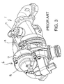
- An adjusting device is provided with a membrane or diaphragm, with an actuating element, for example an actuating rod 18 , connected at one end to the diaphragm and at the other end to a regulating device, to control or regulate charge pressure via the regulating device 19 (see FIG. 3 ).
- control capsule cannot be formed as a preassemblable separate part that can be manufactured independently of the exhaust-gas turbocharger or of the charger housing, because, as stated, the housing lower part is an integral constituent part of the charger housing.
- the charger housing of the exhaust-gas turbocharger has a fastening bracket, whereas the housing lower part and the housing upper part or the housing cover of the control capsule are separate individual parts which can be preassembled because they do not form an integral constituent part of the charger housing.
- the housing lower part and the housing upper part are connected directly to the fastening bracket, which firstly yields the advantage that the connecting points are easily accessible, and secondly, no holders for the housing lower part and for the housing upper part are required because the clamping of said two parts of the control capsule takes place during the course of the mounting thereof on the fastening bracket.
- the connecting device is preferably formed as a screw connection which has at least two screws which, in the assembled state, extend through mounting portions of the housing lower part and of the housing upper part and which can be screwed into threaded recesses of the fastening bracket.
- a conventional holder for the housing upper part and the housing lower part can be dispensed with according to the invention, for preassembly, these need be provided merely with a partial flange formation or at least one clip, usually two clips, which however merely constitutes a transport securing facility in order that the housing upper part does not become detached from the housing lower part on account of the compression spring arranged in the control capsule.
- Claims 5 to 10 define the method according to the invention for manufacturing an exhaust-gas turbocharger.
- the charger housing is manufactured and provided with a fastening bracket, which either may be integrally formed or may constitute a separate component which can be connected in a suitable way to the charger housing.
- said two components are preassembled by being joined together by means of a transport securing facility.
- Subclaims 6 to 10 relate to advantageous refinements of the method according to the invention.
- FIG. 1 shows a perspective illustration of an exhaust-gas turbocharger according to the invention
- FIG. 2 shows a perspective longitudinal section through the control capsule of the exhaust-gas turbocharger
- FIG. 3 shows a prior art turbocharger with control capsule connected to a regulating device via an actuating rod.
- FIG. 1 illustrates an exhaust-gas turbocharger 1 which has a charger housing 2 which is formed in its entirety by a compressor housing 3 , a turbine housing 4 and, arranged between these, a bearing housing 5 for mounting a rotor shaft.
- the rotor shaft with its compressor wheel arranged at the compressor side and its turbine wheel arranged at the turbine side is not shown in FIG. 1 , because the explanation of said components, and also of other conventional components of such turbochargers, is not necessary for explaining the principles of the present invention.
- the exhaust-gas turbocharger 1 is provided with a control device in the form of a control capsule 6 .
- the control capsule 6 has a housing lower part 7 and a housing upper part (housing cover) 8 which, according to the principles of the present invention, are connected by means of a transport securing facility 10 for preassembly.
- the transport securing facility 10 may take the form of a partially flanged portion. It is alternatively possible for one or a multiplicity of clips to be provided for preassembly.
- the control capsule provided with a diaphragm 20 operatively connected with an actuating element, for example an actuating rod 18 to control or regulate charge pressure.
- the spring loaded diaphragm 20 separates the control capsule 6 into an upper chamber and a lower chamber.
- the charger housing 2 is provided, for the final mounting of the control capsule 6 , with a fastening bracket 9 which either may be an integral constituent part of the bearing housing 2 or which may be fixed to the charger housing 2 by means of suitable fastening devices.
- the fastening bracket 9 is arranged on the compressor housing 3 .
- an arrangement on the turbine housing 4 or on the bearing housing 5 is also possible depending on the design of the turbocharger.
- the screw connection 11 has two screws 12 and 13 which, as can be seen in particular from FIG. 2 , extend through two diametrically opposite fastening portions 14 , 14 ′ of the housing upper part 8 and 15 , 15 ′ of the housing lower part 7 and which are screwed into two threaded recesses 16 and 17 of the fastening bracket 9 .
- the mounting direction is indicated in FIGS. 1 and 2 by in each case two arrows MR. It is clear that the mounting takes place from above, that is to say from the side of the housing upper part 8 , wherein the design according to the invention yields a considerable improvement in accessibility to the screw connection 11 .
Landscapes
- Engineering & Computer Science (AREA)
- Mechanical Engineering (AREA)
- General Engineering & Computer Science (AREA)
- Chemical & Material Sciences (AREA)
- Combustion & Propulsion (AREA)
- Chemical Kinetics & Catalysis (AREA)
- General Chemical & Material Sciences (AREA)
- Supercharger (AREA)
Abstract
Description
- 1 Exhaust-gas turbocharger
- 2 Charger housing
- 3 Compressor housing
- 4 Turbine housing
- 5 Bearing housing
- 6 Control capsule
- 7 Housing lower part
- 8 Housing upper part (housing cover)
- 9 Fastening bracket
- 10 Transport securing facility (flanged portion or clip or clips)
- 11 Screw connection
- 12, 13 Screws
- 14, 14′ Fastening portions
- 15, 15′ Fastening portions
- 16, 17 Threaded recesses
- MR Mounting direction
Claims (7)
Applications Claiming Priority (4)
| Application Number | Priority Date | Filing Date | Title |
|---|---|---|---|
| DE102010050733 | 2010-11-08 | ||
| DE102010050733 | 2010-11-08 | ||
| DE102010050733.4 | 2010-11-08 | ||
| PCT/US2011/059045 WO2012064572A2 (en) | 2010-11-08 | 2011-11-03 | Exhaust-gas turbocharger and method for manufacturing the same |
Publications (2)
| Publication Number | Publication Date |
|---|---|
| US20130216375A1 US20130216375A1 (en) | 2013-08-22 |
| US9856752B2 true US9856752B2 (en) | 2018-01-02 |
Family
ID=46051488
Family Applications (1)
| Application Number | Title | Priority Date | Filing Date |
|---|---|---|---|
| US13/882,598 Expired - Fee Related US9856752B2 (en) | 2010-11-08 | 2011-11-03 | Exhaust-gas turbocharger and method for manufacturing the same |
Country Status (5)
| Country | Link |
|---|---|
| US (1) | US9856752B2 (en) |
| KR (1) | KR20130143060A (en) |
| CN (1) | CN103180572B (en) |
| DE (1) | DE112011103228T5 (en) |
| WO (1) | WO2012064572A2 (en) |
Families Citing this family (1)
| Publication number | Priority date | Publication date | Assignee | Title |
|---|---|---|---|---|
| FR2995361B1 (en) * | 2012-09-07 | 2014-08-29 | Snecma | DEVICE FOR CLOSING AN OPENING OF AN ENCLOSURE WALL FOR ACCESSING A ROTARY SHAFT. |
Citations (11)
| Publication number | Priority date | Publication date | Assignee | Title |
|---|---|---|---|---|
| US3136227A (en) * | 1960-08-29 | 1964-06-09 | Rockwell Standard Co | Brake operating mechanism |
| US4056043A (en) * | 1975-10-28 | 1977-11-01 | Johnson Controls, Inc. | Fluid power piston actuators |
| US4517803A (en) * | 1983-04-22 | 1985-05-21 | The Garrett Corporation | Turbocharger compressor valve |
| US5172552A (en) * | 1991-11-12 | 1992-12-22 | Allied-Signal Inc. | Turbocharger with flexible cable wastegate operating linkage |
| US5280872A (en) * | 1992-01-07 | 1994-01-25 | Inax Corporation | Vacuum valve for a sewage collection system |
| US5746058A (en) | 1996-03-11 | 1998-05-05 | Gits Manufacturing Company | Adjustable actuator for a turbocharger |
| US5771774A (en) * | 1996-10-09 | 1998-06-30 | Nai Anchorlok, Inc. | Spring brake actuator having plastic pressure plate assembly |
| US6164187A (en) * | 1997-08-15 | 2000-12-26 | Holland Neway International, Inc. | Diaphragm retainer for spring brake actuator |
| US6189435B1 (en) | 1998-11-30 | 2001-02-20 | Gits Manufacturing Company | Diaphragm |
| US6658846B1 (en) | 1998-07-27 | 2003-12-09 | Holset Engineering Co. Ltd. | Turbocharger with wastegate |
| US7290392B2 (en) | 2005-09-06 | 2007-11-06 | Tia1 Products, Inc. | Wastegate actuator mounting bracket, turbocharger incorporating the bracket, and method of using same |
Family Cites Families (3)
| Publication number | Priority date | Publication date | Assignee | Title |
|---|---|---|---|---|
| JP4495120B2 (en) * | 2006-08-10 | 2010-06-30 | 三菱重工業株式会社 | Multistage turbocharged turbocharger |
| JP4875586B2 (en) * | 2007-10-12 | 2012-02-15 | 三菱重工業株式会社 | 2-stage supercharged exhaust turbocharger |
| DE102007055630A1 (en) * | 2007-11-21 | 2009-05-28 | Bosch Mahle Turbo Systems Gmbh & Co. Kg | Loading system, particularly turbocharger for motor vehicle, has shaft mounted in housing, where shaft carries turbine-sided turbine wheel and compressor-sided compressor wheel |
-
2011
- 2011-11-03 CN CN201180051184.9A patent/CN103180572B/en not_active Expired - Fee Related
- 2011-11-03 US US13/882,598 patent/US9856752B2/en not_active Expired - Fee Related
- 2011-11-03 WO PCT/US2011/059045 patent/WO2012064572A2/en not_active Ceased
- 2011-11-03 KR KR1020137013095A patent/KR20130143060A/en not_active Ceased
- 2011-11-03 DE DE112011103228T patent/DE112011103228T5/en not_active Withdrawn
Patent Citations (11)
| Publication number | Priority date | Publication date | Assignee | Title |
|---|---|---|---|---|
| US3136227A (en) * | 1960-08-29 | 1964-06-09 | Rockwell Standard Co | Brake operating mechanism |
| US4056043A (en) * | 1975-10-28 | 1977-11-01 | Johnson Controls, Inc. | Fluid power piston actuators |
| US4517803A (en) * | 1983-04-22 | 1985-05-21 | The Garrett Corporation | Turbocharger compressor valve |
| US5172552A (en) * | 1991-11-12 | 1992-12-22 | Allied-Signal Inc. | Turbocharger with flexible cable wastegate operating linkage |
| US5280872A (en) * | 1992-01-07 | 1994-01-25 | Inax Corporation | Vacuum valve for a sewage collection system |
| US5746058A (en) | 1996-03-11 | 1998-05-05 | Gits Manufacturing Company | Adjustable actuator for a turbocharger |
| US5771774A (en) * | 1996-10-09 | 1998-06-30 | Nai Anchorlok, Inc. | Spring brake actuator having plastic pressure plate assembly |
| US6164187A (en) * | 1997-08-15 | 2000-12-26 | Holland Neway International, Inc. | Diaphragm retainer for spring brake actuator |
| US6658846B1 (en) | 1998-07-27 | 2003-12-09 | Holset Engineering Co. Ltd. | Turbocharger with wastegate |
| US6189435B1 (en) | 1998-11-30 | 2001-02-20 | Gits Manufacturing Company | Diaphragm |
| US7290392B2 (en) | 2005-09-06 | 2007-11-06 | Tia1 Products, Inc. | Wastegate actuator mounting bracket, turbocharger incorporating the bracket, and method of using same |
Also Published As
| Publication number | Publication date |
|---|---|
| WO2012064572A3 (en) | 2012-07-26 |
| KR20130143060A (en) | 2013-12-30 |
| CN103180572A (en) | 2013-06-26 |
| US20130216375A1 (en) | 2013-08-22 |
| DE112011103228T5 (en) | 2013-07-04 |
| WO2012064572A2 (en) | 2012-05-18 |
| CN103180572B (en) | 2016-03-30 |
Similar Documents
| Publication | Publication Date | Title |
|---|---|---|
| US20170058761A1 (en) | Control arrangement of an exhaust-gas turbocharger | |
| US10400948B2 (en) | Apparatus for regulating at least one fluid flow in a vehicle | |
| US9488096B2 (en) | Actuating force transmitting device of an exhaust-gas turbocharger | |
| CN103097690B (en) | Tolerance-corrected actuator and the manufacture method of correlation | |
| US20100066033A1 (en) | Oil Pan Baffle | |
| JP5965490B2 (en) | Arrangement of air supply device in cylinder head for internal combustion engine | |
| US9359909B2 (en) | Exhaust-gas turbocharger | |
| US20190047531A1 (en) | Electromechanical brake booster and braking system | |
| CN104040142A (en) | Exhaust-gas turbocharger | |
| CN103382883A (en) | Functional module with exhaust gas turbocharger and exhaust manifold | |
| US9856752B2 (en) | Exhaust-gas turbocharger and method for manufacturing the same | |
| US9291137B2 (en) | Device for holding down a valve for metering fuel | |
| JP2015117590A (en) | Engine exhaust system parts mounting structure and engine exhaust system parts mounting method | |
| US20180100605A1 (en) | Method for fastening a conduit on a support by means of freely adjustable captive flanges | |
| US8763628B2 (en) | Electromechanical valve for the pneumatic actuation of a device of an internal combustion engine | |
| CN102844555A (en) | Internal combustion engine comprising a connecting assembly for a cylinder head | |
| US20160222935A1 (en) | Holder for fastening a component to an internal combustion engine | |
| US9388734B2 (en) | Restoring unit, particularly for an internal combustion engine | |
| US8882452B2 (en) | Exhaust gas turbocharger | |
| US20150315962A1 (en) | Overrun air recirculation valve of an exhaust-gas turbocharger compressor | |
| CN102036859B (en) | Airbag module | |
| KR101779869B1 (en) | Socket joint with integrated tube anchors | |
| US8327640B2 (en) | Adjustment device on an exhaust-driven turbocharger | |
| US20150176433A1 (en) | Turbine housing for an exhaust gas turbocharger | |
| EP2792870B1 (en) | Exhaust gas turbocharger with adjusting drive |
Legal Events
| Date | Code | Title | Description |
|---|---|---|---|
| AS | Assignment |
Owner name: BORGWARNER INC., MICHIGAN Free format text: ASSIGNMENT OF ASSIGNORS INTEREST;ASSIGNOR:CHRISTMANN, RALF;REEL/FRAME:030877/0937 Effective date: 20111104 |
|
| STCF | Information on status: patent grant |
Free format text: PATENTED CASE |
|
| FEPP | Fee payment procedure |
Free format text: MAINTENANCE FEE REMINDER MAILED (ORIGINAL EVENT CODE: REM.); ENTITY STATUS OF PATENT OWNER: LARGE ENTITY |
|
| LAPS | Lapse for failure to pay maintenance fees |
Free format text: PATENT EXPIRED FOR FAILURE TO PAY MAINTENANCE FEES (ORIGINAL EVENT CODE: EXP.); ENTITY STATUS OF PATENT OWNER: LARGE ENTITY |
|
| STCH | Information on status: patent discontinuation |
Free format text: PATENT EXPIRED DUE TO NONPAYMENT OF MAINTENANCE FEES UNDER 37 CFR 1.362 |
|
| FP | Lapsed due to failure to pay maintenance fee |
Effective date: 20220102 |