US9856115B2 - Systems and methods for handrail cleaning - Google Patents
Systems and methods for handrail cleaning Download PDFInfo
- Publication number
- US9856115B2 US9856115B2 US15/294,721 US201615294721A US9856115B2 US 9856115 B2 US9856115 B2 US 9856115B2 US 201615294721 A US201615294721 A US 201615294721A US 9856115 B2 US9856115 B2 US 9856115B2
- Authority
- US
- United States
- Prior art keywords
- handrail
- pad
- cleaning
- mobile base
- slider
- Prior art date
- Legal status (The legal status is an assumption and is not a legal conclusion. Google has not performed a legal analysis and makes no representation as to the accuracy of the status listed.)
- Expired - Fee Related
Links
Images


Classifications
-
- A—HUMAN NECESSITIES
- A47—FURNITURE; DOMESTIC ARTICLES OR APPLIANCES; COFFEE MILLS; SPICE MILLS; SUCTION CLEANERS IN GENERAL
- A47L—DOMESTIC WASHING OR CLEANING; SUCTION CLEANERS IN GENERAL
- A47L25/00—Domestic cleaning devices not provided for in other groups of this subclass
-
- B—PERFORMING OPERATIONS; TRANSPORTING
- B66—HOISTING; LIFTING; HAULING
- B66B—ELEVATORS; ESCALATORS OR MOVING WALKWAYS
- B66B31/00—Accessories for escalators, or moving walkways, e.g. for sterilising or cleaning
- B66B31/02—Accessories for escalators, or moving walkways, e.g. for sterilising or cleaning for handrails
-
- B08B1/006—
-
- B08B1/02—
-
- B—PERFORMING OPERATIONS; TRANSPORTING
- B08—CLEANING
- B08B—CLEANING IN GENERAL; PREVENTION OF FOULING IN GENERAL
- B08B1/00—Cleaning by methods involving the use of tools
- B08B1/10—Cleaning by methods involving the use of tools characterised by the type of cleaning tool
- B08B1/14—Wipes; Absorbent members, e.g. swabs or sponges
- B08B1/143—Wipes
-
- B—PERFORMING OPERATIONS; TRANSPORTING
- B08—CLEANING
- B08B—CLEANING IN GENERAL; PREVENTION OF FOULING IN GENERAL
- B08B1/00—Cleaning by methods involving the use of tools
- B08B1/20—Cleaning of moving articles, e.g. of moving webs or of objects on a conveyor
-
- B—PERFORMING OPERATIONS; TRANSPORTING
- B08—CLEANING
- B08B—CLEANING IN GENERAL; PREVENTION OF FOULING IN GENERAL
- B08B3/00—Cleaning by methods involving the use or presence of liquid or steam
- B08B3/04—Cleaning involving contact with liquid
- B08B3/041—Cleaning travelling work
-
- B—PERFORMING OPERATIONS; TRANSPORTING
- B62—LAND VEHICLES FOR TRAVELLING OTHERWISE THAN ON RAILS
- B62B—HAND-PROPELLED VEHICLES, e.g. HAND CARTS OR PERAMBULATORS; SLEDGES
- B62B3/00—Hand carts having more than one axis carrying transport wheels; Steering devices therefor; Equipment therefor
- B62B3/02—Hand carts having more than one axis carrying transport wheels; Steering devices therefor; Equipment therefor involving parts being adjustable, collapsible, attachable, detachable or convertible
-
- B—PERFORMING OPERATIONS; TRANSPORTING
- B62—LAND VEHICLES FOR TRAVELLING OTHERWISE THAN ON RAILS
- B62B—HAND-PROPELLED VEHICLES, e.g. HAND CARTS OR PERAMBULATORS; SLEDGES
- B62B2202/00—Indexing codes relating to type or characteristics of transported articles
- B62B2202/50—Cleaning or gardening articles
Definitions
- This invention relates generally to handrails, and, more specifically, to systems and methods for handrail cleaning.
- Handrails are used on stairwells, ADA ramps, escalators, and many walkways to help users maintain balance and safety. As such, handrails are contacted by human hands and all the elements carried thereon, as well as elements found in buildings and the outdoors. Handrails are shown to harbor bacteria and viruses, and therefore need to be cleaned regularly to maintain the health and safety of users, especially children, the elderly, and others who may be immunocompromised. Cleaning handrails can carry its own hazard, as one may be required to traverse lean out over the pathway in order to clean it. Moreover, cleaning handrails can be a time consuming though menial task, diverting human labor from more demanding tasks. The invention disclosed herein aims to simplify the handrail cleaning process by increasing productivity, safety, and ease of cleaning handrails.
- This invention relates generally to handrails, and, more specifically, to systems and methods for handrail cleaning.
- the system is comprised essentially of a cleaning pad and a means to deploy the cleaning pad.
- the system for cleaning a handrail comprises at least one strut with a far end and a near end; and at least one pad disposed on the far end of the strut.
- the system further comprises a pad disposed on the far end of the strut which may be configured to wrap around at least a portion of the handrail.
- the pad disposed on the far end of the strut substantially conforms to the shape of the handrail.
- the pad disposed on the far end of the strut may be pivotably coupled with the strut.
- the pad disposed on the far end of the strut may be configured to slide onto and off of the handrail at an end of the handrail.
- the near end of the strut may include a handle. In some embodiments, the near end of the strut may be disposed on a support structure. In some embodiments, the near end of the strut may be pivotably disposed on a support structure. In some embodiments, system for cleaning a handrail may further comprise a first strut and a second strut, the second strut disposed below the first, wherein the near end of the second strut may be disposed on the support structure; a first pad and a second pad, the second pad disposed on the far end of the second strut; wherein the first pad and the second pad are substantially aligned through a vertical plane. In some embodiments, the support structure may be disposed on four wheels. In some embodiments, the four wheels may be casters. In other embodiments, two of the four wheels may be casters, and the other two wheels may not be casters.
- the system for cleaning a handrail comprises a support structure; a strut disposed on a forward portion of the support structure; a first pad, the first pad disposed on the strut; and a second pad, the second pad disposed on the strut below the first pad.
- the system for cleaning a handrail comprises at least one support structure; at least one strut with a near end and a far end, wherein the near end may be disposed on a forward portion of the at least one support structure; at least one pad disposed on the far end of the at least one strut.
- the first pad and the second pad may be disposed such that the first pad and second pad may be substantially aligned along a vertical plane.
- the first pad and the second pad may be disposed such that a handrail travels first through the first pad and then through the second pad.
- the strut may be further comprised of a substantially straight portion with a first end and a second end, wherein the first end may be coupled with the forward portion of the support structure; and a mounting bracket disposed on the second end of the strut, the bracket further comprising an upper mount and a lower mount.
- the first pad may be disposed on the upper mount of the mounting bracket and the second pad may be disposed on the lower mount of the mounting bracket.
- the system for cleaning a handrail comprises a support structure; a strut with a first end and a second end, wherein the first end is disposed on the support structure; a mounting bracket with an upper mount and a lower mount, the mounting bracket disposed on the second end of the strut; a first pad disposed on the upper mount; and a second pad disposed on the lower mount.
- the system for cleaning a handrail further comprises casters disposed on a front edge of the support structure.
- the system for cleaning a handrail further comprises wheels disposed on a back edge of the support structure.
- FIG. 1 is an isometric view of one embodiment of a system for cleaning escalator handrails in the extended or operating position.
- FIG. 2 is an environmental isometric view thereof.
- FIG. 3 is an environmental side view thereof.
- FIG. 4 is a side view of one embodiment thereof.
- FIG. 5 is an exploded view of a portion thereof.
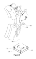
- FIG. 6 is an isometric view of one embodiment of a system for cleaning escalator handrails in the maintenance position.
- FIG. 7 is a close up view of a portion of one embodiment of a system for cleaning escalator handrails in the maintenance position.
- FIG. 8 is an isometric view of one embodiment of a system for cleaning escalator handrails in the storage position.
- FIG. 9 is a side view thereof.
- FIG. 10 is a view of the underside of one embodiment of a system for cleaning escalator handrails.
- FIG. 11 is an isometric view of one embodiment of a cleaning element for a system for cleaning escalator handrails.
- FIG. 12 a is a front view thereof.
- FIG. 12 b is a side view thereof.
- FIG. 13 is an isometric view of one embodiment of a system for cleaning ADA handrails in the retracted position.
- FIG. 14 is an isometric view of one embodiment of a system for cleaning ADA handrails in the extended position.
- FIG. 15 is an exploded isometric view of a system for cleaning ADA handrails.
- FIG. 16 is an isometric view of one embodiment of a cleaning element arrangement of a system for cleaning ADA handrails.
- FIG. 17 is a front view thereof.
- FIG. 18 a is a right side view thereof.
- FIG. 18 b is a left side view thereof.
- FIG. 19 is an exploded isometric view of another embodiment of the system for cleaning ADA handrails.
- FIG. 20 is an isometric view of another embodiment of the system for cleaning escalator handrails.
- FIG. 21 is an isometric view of another embodiment of the system for cleaning escalator handrails.
- FIG. 22 is a right-side view thereof.
- This invention relates generally to handrails, and, more specifically, to systems and methods for handrail cleaning. Specific details of certain embodiments of the invention are set forth in the following description and in FIGS. 1-19 to provide a thorough understanding of such embodiments.
- the present invention may have additional embodiments, may be practiced without one or more of the details described for any particular described embodiment, or may have any detail described for one particular embodiment practiced with any other detail described for another embodiment.
- inventive aspects in any particular “embodiment” within this detailed description, and/or a grouping of limitations in the claims presented herein, is not intended to be a limiting disclosure of those particular aspects and/or limitations to that particular embodiment and/or claim.
- inventive entity presenting this disclosure fully intends that any disclosed aspect of any embodiment in the detailed description and/or any claim limitation ever presented relative to the instant disclosure and/or any continuing application claiming priority from the instant application (e.g. continuation, continuation-in-part, and/or divisional applications) may be practiced with any other disclosed aspect of any embodiment in the detailed description and/or any claim limitation.
- FIG. 1 is an isometric view of one embodiment of a system for cleaning escalator handrails in the operating position.
- the system is comprised essentially of a cart arrangement 100 and a cleaning pad arrangement 200 .
- cart 100 may include a handle 110 .
- Handle 110 may be multipurpose. First, handle 110 may be used to push or pull cart 100 into a proper position. Second, handle 110 may be used to engage or disengage spring 111 , which in turn engages or disengages handle brake 112 .
- brake 112 normally engages wheel 172 , and handle 110 must be manipulated in order to disengage brake 112 . For instance, in some embodiments, handle 110 is depressed, which causes spring 111 to lift brake 112 , disengaging wheel 172 . When handle 110 is released, spring 111 is released and brake 112 engages rear wheel 172 , preventing motion of the cart. In other embodiments, handle 110 must be lifted in order to disengage brake 112 . When handle 110 is released, brake 112 engages rear wheel 172 , preventing motion of the cart.
- brake 112 is normally disengaged, and handle 110 must be manipulated in order to brake wheel 172 .
- handle 110 may be lifted into a locked position, causing spring 111 to depress brake 112 and engage wheel 172 .
- handle 110 may be depressed into a locked position, causing spring 111 to shift brake 112 and engage rear wheel 172 .
- Spring 111 may be a compression spring, a clock spring, a torsion spring, a tension spring, or any other type of tension device without altering the function of the spring.
- handle 100 may be metallic, plastic, wood, may be curved, straight, or any other shape or material without altering the function of the handle.
- cart 100 may include a receptacle 120 .
- Receptacle 120 may be used for refuse, or to store or transport other elements of the present invention.
- Receptacle 120 may have an opening at the top of the cart, may contain a lid (not depicted), may be removable or replaceable, and may be comprised of a rigid or flexible material as the application calls for.
- cart 100 may also include at least one tray 130 .
- tray 130 may be used to store the cleaning solution used with the present invention.
- tray 130 may be used to store or transport additional cleaning pads or elements of the present invention.
- Tray 130 may be comprised of any rigid or semi-rigid material.
- tray 130 may be comprised of a material that has particular characteristics, such as non-reactivity with the recommended cleaning solution, rust resistance, strength or heat characteristics, etc.
- tray 130 is supported by beams 140 .
- beams 140 may be four in number. In other embodiments, beams 140 may be three in number as depicted in FIG. 1 .
- cart 100 may include a second tray 131 . Tray 131 may serve any of the purposes of tray 130 .
- cart 100 may include a base 170 .
- Base 170 is the support structure for cart 100 , and as such can be any rigid material without impacting the function of the base.
- base 170 may include front wheels 171 . Wheels 171 will tend to be smaller than rear wheels 172 to allow for better maneuverability of cart 100 , but in some embodiments the front wheels may be substantially the same size as or even larger than rear wheels 172 . In some embodiments, wheels 172 may be covered by a portion of base 170 , such as a wheel guard 175 .
- base 170 may include a bracket 173 , with which struts 160 are coupled. Bracket 173 may be fastened onto base 170 in any number of ways so long as the bracket is substantially immobile. Strut 160 may be fastened onto bracket 173 in any number of ways so long as it can rotate about the fastener, as the strut is designed to be moveable.
- strut 160 may be a single strut. In some embodiments, strut 160 may be comprised of multiple arms, such as forward arms 161 and rearward arms 162 . In some embodiments, strut 160 may be comprised of 1, 2, 3, 4, or more individual arms.
- each arm may move in tandem or individually, depending on the need of the particular application.
- strut 160 is comprised of two forward arms 161 and two rearward arms 162 , wherein the lower portions of both sets of arms are mounted to the forward and rearward portions of bracket 173 , respectively.
- the upper portions are coupled with a crossbar 165 , which causes the individual arms to move in tandem.
- Crossbar 165 is further coupled with the mounting bracket, which is better depicted in FIG. 3 .
- FIG. 2 is an isometric view of one embodiment of the system for cleaning escalator handrails in the operating position and in use.
- strut 160 is extended, allowing cleaning elements 200 to be positioned around an escalator handrail 270 .
- the details pertaining to cleaning elements 200 are better disclosed in other figures, which will be discussed further herein.
- FIGS. 3 and 4 are side views of one embodiment of the system for cleaning escalator handrails.
- FIG. 3 shows the system with an escalator handrail.
- FIG. 4 is the system alone for illustrative purposes. These figures better illustrate the remainder of strut 160 and the integration with mounting bracket 150 , otherwise known as the cleaning pad carriage.
- stopper 180 there may be a stopper 180 between the cart base 170 and the strut 160 .
- stopper 180 may be fixed, providing a constant position for strut 160 when the strut is extended into the operating position.
- stopper 180 may be adjustable.
- stopper 180 may be adjusted by turning the knurled knob 181 .
- stopper 180 may be adjusted by loosening the stopper from the attachment to the base 170 and rotating it with respect to the plane of the base.
- strut 160 may further include a positional element 163 .
- a function of positional element 163 is to aid in the positioning and stability of cleaning elements 200 .
- positional element 163 may be a pneumatic or hydraulic cylinder.
- positional element 163 may be a gas spring.
- positional element 163 may be any other type of linear spring. The reciprocating linear motion of positional element 163 may be achieved in many manners without altering the function of the element.
- Strut 160 is coupled with mounting bracket 150 .
- the joint between strut 160 and bracket 150 is fixed.
- the joint between strut 160 and bracket 150 is movable.
- mounting bracket 150 rotates around the joint with strut 160 , allowing the mounting bracket and cleaning elements 200 to have a different position relative to strut 160 . See FIGS. 6 and 9 for examples. Allowing mobility in the joint between strut 160 and bracket 150 further allows cleaning elements 200 to be positioned more accurately with respect to cart 100 and escalator handrail 270 .
- the joint between may allow movement in only one direction.
- the joint may allow movement in two or more directions.
- the joint may be a ball joint, allowing almost 100 percent freedom of motion.
- the joint may allow movement in three or more axes.
- mounting bracket 150 may have only one mount. In a preferred embodiment, mounting bracket 150 has two mounts, an upper mount 151 and a lower mount 152 . In this configuration, a user is able to clean escalator handrail 270 by passing the handrail through both the upper and lower cleaning elements. In one method of use, a user soaks one cleaning element 200 in a cleaning solution and mounts it on lower mount 152 . A dry cleaning element 200 is mounted on upper mount 151 , and the cleaning elements are flexed to fit snugly around handrail 270 . Handrail 270 is cleaned as it passes first through the wet cleaning element and then through the dry element. Note the direction of travel 280 as depicted in FIG. 3 .
- the particular direction of travel is recommended because it allows the handrail to dry more completely as it runs the length of the escalator. This is important for at least three reasons.
- the first is that it prevents dust and other debris from the escalator mechanism, such as rollers and guides, from collecting on the handrail.
- a wet handrail entering the system may cause disruptions in the guidance and tracking of the drive system, causing damage to the handrail and escalator as a whole.
- placing the handrail cleaner at the newel (emerging) end of the escalator helps to prevent a situation in which any part of the handrail cleaner is caught on the handrail and is entrapped by the handrail system. Since the handrail is emerging, any element that becomes caught on the handrail can be pulled off before entering the system, eliminating the damage and safety risks involved in items becoming entrapped in the handrail system.
- a dry cleaning element 200 is mounted on upper mount 151 , and a polish or conditioner could be placed on the cleaning element that is mounted on lower mount 152 .
- the cleaning solution may include a polish or conditioner, and the dry element may act as a dryer and buffer.
- cleaning elements 200 are coupled with mounts 151 and 152 via fasteners 153 .
- fasteners 153 are permanent.
- fasteners 153 are removable to allow for easy installation and removal of cleaning elements 200 .
- fasteners 153 may be quick release fasteners, such as push-button pins, quarter-turn fasteners, tension latches, push turn fasteners, or any other easily removed standard fastener.
- FIG. 5 is an exploded view of one embodiment of the joint between strut 160 and mounting bracket 150 .
- strut 160 has a forward arm set 161 and a rearward arm set 162 .
- Positional element 163 can be seen, disposed between the sets of arms that comprise the strut 160 .
- forward arms 161 may be joined by fastener 166 .
- rearward arms 161 may be joined by a fastener 167 .
- fastener 166 or fastener 167 may be further disposed through mounting bracket 150 .
- mounting bracket 150 may rotate about the fastener 166 or 167 to allow alternative positioning of the bracket.
- the right and left arm sets may be joined through a center bracket 164 .
- the center bracket 164 may house latch 190 .
- latch 190 may have a first notch 191 , a second notch 192 , and a third notch 193 . This particular feature and alternative positioning are discussed in more depth with FIG. 7 .
- FIG. 6 is an isometric view of one embodiment of the system for cleaning escalator handrails wherein the system is in the cleaning element change position.
- bracket 150 can be rotated such that mounts 151 and 152 are substantially parallel to the base 170 . This allows a user to change the cleaning elements 200 , or portions thereof, more easily.
- bracket 150 can be rotated to present cleaning elements 200 for easy and rapid change.
- bracket 150 When bracket 150 is rotated, its plane is substantially horizontal, or substantially parallel to the plane of base 170 (not depicted in this figure), which allows easy access to cleaning elements 200 .
- mounting bracket 150 is coupled with a latch 190 .
- latch 190 is engaged to prevent the bracket from returning to its in-use position.
- latch 190 is used to hold bracket 150 in any position, including the in-use position, for additional structural integrity.
- latch 190 may be used to release bracket 190 from the in-use position to allow movement to an alternative position.
- latch 190 may have a first notch 191 . When bracket 150 is rotated into the changing position, notch 191 may engage catch 194 , holding the bracket in that position. In other embodiments, latch 190 may have a first notch 191 and a second notch 192 .
- latch 190 may have a first notch 191 , a second notch 192 , and a third notch 193 , each notch allowing a different position of mounting bracket 150 .
- latch 190 may include a spring 195 .
- Spring 195 may be used to establish a “standard” position for bracket 150 , allowing the bracket to return to that position when the latch is disengaged from catch 194 .
- spring 195 may simply provide a counter force to the force exerted by bracket 150 on the rest of the system when the bracket is in any position. As depicted in FIG. 7 , spring 195 is a torsion spring. However, spring 195 may be a compression spring, a clock spring, a tension spring, or any other type of spring without altering its function.
- FIG. 8 is an isometric view of one embodiment of the system for cleaning escalator handrails in the storage position.
- FIG. 9 is a side view thereof. In this position, strut 160 is retracted so that it is substantially vertical, as opposed to when the system is in the operating position, wherein the strut is at a nearly 45 degree angle to vertical.
- cart 100 may include a latch to maintain the storage position. In other embodiments, the storage position may be maintained by the linear spring 163 , or by some combination of the linear spring and a separate locking mechanism.
- FIG. 10 is a bottom view of one embodiment of the system for cleaning escalator handrails.
- Bracket 173 to which the strut (not depicted) is fastened, is disposed through the surface of base 170 .
- the fasteners coupling bracket 173 to base 170 may be permanent, such as, for example, rivets.
- the fasteners may be removable, such as nuts and bolts. It may be of value in particular applications to allow the entire strut to be replaced, or to move the strut assembly from a base that has been damaged to one that is intact. Therefore, any number of fasteners can be used in this position without altering the function of the base 170 and bracket 173 .
- FIG. 11 is an isometric view of one embodiment of cleaning element 200 .
- Cleaning element 200 is comprised of a substantially flexible form 210 .
- the flexible form 210 may be any flexible material, such plastics, foam, or any number of composites.
- the flexible form 210 may be comprised of a non-reactive or substantially inert material, such as silicone, silicone rubber, Teflon, and others.
- a primary function of flexible form 210 is to provide the specific shape of the cleaning element 200 , allowing the element to substantially conform to and almost completely cover the surface and sides of the handrail, while still being flexible enough to be placed onto or removed from the handrail without damaging either the handrail or the form.
- flexible form 210 will almost certainly come into contact with at least a cleaning solution, many of which contain at least one caustic or chemically abrasive ingredient.
- Flexible form 210 is also likely to come into contact with polishes, waxes, and the handrail material. As such, the material properties of flexible form 210 may become relevant in a particular application. Therefore, many flexible materials may work without altering either the primary or secondary functions of the flexible form 210 , and may be changed as necessary for a particular application.
- Cleaning element 200 may also include a cleaning cloth 240 .
- Cloth 240 may be microfiber, cotton, terrycloth, or any number of standard cleaning cloth materials, but a preferred embodiment uses microfiber for its ability to hold moisture as well as collect and hold debris. In this application, cleaning cloth 240 will often be required to both hold a cleaning solution and trap any debris that is dislodged in the cleaning process, an application for which microfiber is particularly well suited.
- Cleaning cloth 240 is designed to sit flush against the inner portion of form 210 , covering the entire surface. In order to do so, it must be held onto form 210 in some way that does not obstruct the function of cleaning cloth 240 .
- One solution is to use support cloth 230 .
- support cloth 230 is coupled with cleaning cloth 240 on a seam 231 that approximately follows the edge between the inner and outer portions of form 210 .
- Support cloth 230 and cleaning cloth 240 are stretched over form 210 , leaving a spot at the top for the form to protrude and allow access to pinhole 260 .
- the cloths are held onto form 210 by strap 220 , which is disposed through a slit 250 in the top of the flexible form.
- support cloth 230 may be elastic enough to maintain its position on form 210 without use of the strap.
- strap 220 may connect directly with cleaning cloth 240 .
- cloths 230 and 240 may be one material that is disposed on form 210 in any of the above methods.
- Pinhole 260 is the point at which form 210 would be joined with mounting bracket 150 via pin 153 . This is discussed in more detail above.
- FIG. 12 a is a front view of cleaning element 200 .
- the contour from side to side of cleaning element 200 is designed to cover the top and sides of a handrail, fitting snugly thereon to allow the cleaning cloth 240 to touch all surfaces of the handle that a user might touch.
- FIG. 12 b is a side view, showing the contour of cleaning element 200 from front to back. This is a non-limiting example wherein the embodiment depicted has a slight curve.
- the system for cleaning escalator handrails may be disposed at the end of the escalator, where the handrail emerges from the floor and begins to run the length of the escalator.
- a slightly curved longitudinal profile allows cleaning element 200 to maintain contact with the handrail newel end for slightly longer, giving a better clean and reducing friction points between the handrail and the cleaning element, which ultimately reduces wear on the system.
- the longitudinal contour is substantially straight, allowing the system to be used on moving walkways or other parts of an escalator where there is no curve in the handrail to be accounted for.
- FIG. 13 is an isometric view of one embodiment of an ADA handrail cleaner.
- a cleaning element 200 is attached to a handle element 300 .
- the handle 300 may be a fixed length.
- the handle 300 may be a retractable telescoping handle, as seen in FIG. 14 .
- the telescoping handle 300 embodiment may include one or more sections 301 wherein the sections are progressively slightly smaller such that the majority of the handle can be retracted into the length of a single section. In FIG. 14 , this feature can be seen as each section gets smaller in diameter the farther the handle gets from cleaning element 200 .
- each section may be joined to another with a locking mechanism 302 .
- locking mechanism 301 may be a clamping lever, a twist lock, or any other telescope locking mechanism.
- handle 300 may include a return spring, such that when the locking mechanism 301 is released, the handle portions automatically retract into one another. This telescoping mechanism allows a user to extend cleaning element 200 along the length of the handle without having to stand on the stairs or ramp to do so, making the cleaning process both safer and more ergonomically sound.
- FIG. 15 is an exploded view of one embodiment of the ADA handrail cleaner.
- Handle 300 is coupled with cleaning element 200 by the addition of a socket 310 , a bracket 320 , a thumb screw 330 , and a bolt 340 .
- Bracket 320 is coupled with flexible form 210 via pin 153 , which, like with the escalator handrail cleaner embodiment, is disposed through the form in pinhole 260 .
- bracket 320 may include one or more gaskets 321 .
- bracket 320 may be rigidly coupled to form 210 , such that handle 300 is at a constant angle to cleaning element 200 .
- bracket 320 may be coupled with form 210 in a manner that allows rotation of handle 300 with respect to cleaning element 200 .
- handle 300 may be movable along the longitudinal plane, such that the handle can go from substantially horizontal to substantially vertical.
- handle 300 may pivot universally, allowing the handle to move in any plane around cleaning element 200 . This type of embodiment may be useful for curved stairways or ramps, or in sending the cleaning element 200 around a corner.
- Fastener 340 is disposed through a hole in bracket 320 , and socket 310 is threaded onto the fastener.
- fastener 340 may be a permanent fastener, such as a rivet.
- fastener 340 may be removable, such as a bolt.
- fastener 340 may be knurled to allow installation and removal without the use of tools.
- FIGS. 16, 17, and 18 are detailed views of cleaning element 200 with the modifications for use with handle 300 .
- FIG. 16 is an isometric view, showing the bracket 320 coupled with form 210 by pin 160 . It also shows that cleaning element 200 is substantially identical to the cleaning element as used in the escalator handrail cleaning embodiment.
- Cleaning element 200 has a cleaning cloth 240 coupled with a support cloth 230 and coupled with plastic form 210 by strap 220 . While the variations of cleaning element 200 are not repeated here, all of the variations disclosed above still apply.
- cleaning element 200 may be a slightly different size in the ADA application than it is in the escalator application, but it performs the same function.
- FIG. 17 is a front view of one embodiment of cleaning element 200 .
- This view shows the joint of bracket 320 to socket 310 .
- Socket 310 is coupled with bracket 320 by a fastener 340 , which passes through a hole in bracket 320 and into a threaded receiving portion on the bottom of socket 310 .
- Thumb screw 330 allows a user to clamp handle 300 (not shown) into socket 310 .
- FIG. 18 a is a right side view of one embodiment of cleaning element 200 with bracket 320 , socket 310 , and screw 330 installed, wherein the bracket is coupled with the cleaning element 200 by pin 160 .
- FIG. 18 b is a left side view thereof.
- FIG. 19 is an exploded isometric view of a different embodiment of the handrail cleaner.
- cleaning element 200 is comprised of the substantially flexible form 210 and cleaning cloth 240 as discussed in FIG. 11 .
- cleaning cloth 240 may include strap 241 .
- Strap 241 may be used to hold pad 240 onto form 210 with the assistance of strap 220 and spring clips 243 , wherein strap 220 is disposed through a slit 250 in the top of the flexible form and held in place with clips 243 . Strap 241 is then coupled with strap 220 , holding the cloth 240 in place, while spring clips 243 hold strap 242 to form 210 .
- This embodiment of cloth 240 is compatible with either the escalator handrail cleaning mechanism or the ADA handrail cleaning mechanism.
- Pinhole 260 remains accessible for use on the handrail cleaner, and the ball 420 and socket 421 joint permits use as the ADA handrail cleaner.
- the ball 420 and socket 421 joint also permits a greater degree of mobility between the handle 300 and the cleaner 200 , as the ball snaps into the socket, but still rotates freely within.
- FIG. 20 is an isometric view of a different embodiment of the escalator handrail cleaner.
- positional element 163 is coupled with a two-part base, wherein the lower portion 176 and the upper portion 177 are joined by fasteners 178 , leaving a gap between the upper and lower base portions.
- the mounting bracket 150 may be further positionable via thumbscrew 196 , which can be turned to loosen or tighten a clamp to allow for the mounting bracket to be raised or lowered.
- FIG. 21 shows that, in some embodiments, the two-part base may be operatively coupled with a slider portion 179 , which may be free standing or may be mounted to a floor or the cart base 170 .
- Clamp 197 is operatively coupled with the two-part base, providing a locking mechanism by which the base can either be held in place or, when the clamp is released, permits the base to slide along the slider portion 179 .
- FIG. 22 is a right side view of the slider embodiment, showing claim 197 in position relative to the two-part base and the slider, as well as thumb-screw 198 , which is configured to allow the mounting bracket to be moved, tilted, removed, or replaced.
Landscapes
- Engineering & Computer Science (AREA)
- Chemical & Material Sciences (AREA)
- Combustion & Propulsion (AREA)
- Transportation (AREA)
- Mechanical Engineering (AREA)
- Escalators And Moving Walkways (AREA)
Abstract
Description
Claims (19)
Priority Applications (5)
| Application Number | Priority Date | Filing Date | Title |
|---|---|---|---|
| US15/294,721 US9856115B2 (en) | 2015-06-20 | 2016-10-15 | Systems and methods for handrail cleaning |
| CN201710961033.6A CN107951454A (en) | 2016-10-15 | 2017-10-13 | Systems and methods for handrail cleaning |
| US15/859,868 US10329125B2 (en) | 2014-09-17 | 2018-01-02 | Systems and methods for handling cleaning |
| US15/977,978 US10287134B2 (en) | 2014-09-17 | 2018-05-11 | Systems and methods for handrail cleaning |
| US16/412,304 US10618779B2 (en) | 2014-09-17 | 2019-05-14 | Systems and methods for handrail cleaning |
Applications Claiming Priority (2)
| Application Number | Priority Date | Filing Date | Title |
|---|---|---|---|
| US14/745,412 US9764929B2 (en) | 2014-09-17 | 2015-06-20 | Systems and methods for handrail cleaning |
| US15/294,721 US9856115B2 (en) | 2015-06-20 | 2016-10-15 | Systems and methods for handrail cleaning |
Related Parent Applications (1)
| Application Number | Title | Priority Date | Filing Date |
|---|---|---|---|
| US14/745,412 Continuation-In-Part US9764929B2 (en) | 2014-09-17 | 2015-06-20 | Systems and methods for handrail cleaning |
Related Child Applications (1)
| Application Number | Title | Priority Date | Filing Date |
|---|---|---|---|
| US15/859,868 Continuation US10329125B2 (en) | 2014-09-17 | 2018-01-02 | Systems and methods for handling cleaning |
Publications (2)
| Publication Number | Publication Date |
|---|---|
| US20170029250A1 US20170029250A1 (en) | 2017-02-02 |
| US9856115B2 true US9856115B2 (en) | 2018-01-02 |
Family
ID=57885830
Family Applications (2)
| Application Number | Title | Priority Date | Filing Date |
|---|---|---|---|
| US15/294,721 Expired - Fee Related US9856115B2 (en) | 2014-09-17 | 2016-10-15 | Systems and methods for handrail cleaning |
| US15/859,868 Active US10329125B2 (en) | 2014-09-17 | 2018-01-02 | Systems and methods for handling cleaning |
Family Applications After (1)
| Application Number | Title | Priority Date | Filing Date |
|---|---|---|---|
| US15/859,868 Active US10329125B2 (en) | 2014-09-17 | 2018-01-02 | Systems and methods for handling cleaning |
Country Status (2)
| Country | Link |
|---|---|
| US (2) | US9856115B2 (en) |
| CN (1) | CN107951454A (en) |
Families Citing this family (14)
| Publication number | Priority date | Publication date | Assignee | Title |
|---|---|---|---|---|
| EP3333419A3 (en) * | 2016-12-08 | 2018-09-12 | Panasonic Intellectual Property Management Co., Ltd. | Actuator device |
| US10399825B1 (en) * | 2017-10-21 | 2019-09-03 | Ori Rosenbaum | Handrail cleaning apparatus and method |
| USD869811S1 (en) * | 2017-12-13 | 2019-12-10 | Lg Innotek Co., Ltd. | Sterilizer for escalator handrail |
| CN108209736B (en) * | 2018-01-29 | 2020-12-25 | 陈爱珍 | Use method of running water type handrail belt cleaning equipment |
| CN108296192B (en) * | 2018-01-31 | 2019-08-23 | 池云飞 | A kind of application method of folding cleaning device |
| CN108190716B (en) * | 2018-01-31 | 2023-08-25 | 张文 | Foldable cleaning device |
| EP3569560A1 (en) * | 2018-05-11 | 2019-11-20 | Christian E. Thomsen | Systems and methods for handrail cleaning |
| CN108821084A (en) * | 2018-08-27 | 2018-11-16 | 临海市奥特休闲用品股份有限公司 | A kind of cleaning device of elevator handrail |
| CN110773477B (en) * | 2019-10-14 | 2022-05-03 | 江苏泰祥电线电缆有限公司 | Cable surface cleaning device |
| CN110893401B (en) * | 2019-12-14 | 2022-02-01 | 解恒苏 | Road and bridge belt cleaning device |
| CN111058684B (en) * | 2019-12-30 | 2021-05-28 | 温州斯酷睿机械科技有限公司 | Self-cleaning fence handrail |
| CN111908304B (en) * | 2020-07-16 | 2021-06-04 | 深圳市千福之家养老产业有限公司 | A smart handrail |
| CN113458044A (en) * | 2021-07-21 | 2021-10-01 | 赵峰 | Automatic cleaning, disinfecting and drying integrated device for escalator handrails and using method |
| US12344298B2 (en) * | 2022-06-29 | 2025-07-01 | Clyde Smith | Foldable transport cart for planar materials |
Citations (3)
| Publication number | Priority date | Publication date | Assignee | Title |
|---|---|---|---|---|
| US7194783B1 (en) * | 2004-02-20 | 2007-03-27 | Gene C. Hunt | Window blind cleaning apparatus |
| US7389866B2 (en) * | 2004-11-30 | 2008-06-24 | Mitsubishi Denki Kabushiki Kaisha | Device and method for repairing moving handrail of passenger conveyor |
| US8261401B1 (en) * | 2011-03-10 | 2012-09-11 | Maria Ciesielski | Cleaning tool device for vertical blinds |
Family Cites Families (12)
| Publication number | Priority date | Publication date | Assignee | Title |
|---|---|---|---|---|
| US3946853A (en) * | 1973-09-27 | 1976-03-30 | Koji Ishida | Escalator belt cleaner |
| US6682806B1 (en) | 1999-02-19 | 2004-01-27 | Ronald H. Ball | Method of applying a protective film, optionally including advertising or other visible material, to the surface of a handrail for an escalator or moving walkway |
| US7430781B2 (en) * | 2004-12-18 | 2008-10-07 | Collins Linda M | Window blind cleaning system |
| ITTO20080494A1 (en) * | 2008-06-24 | 2009-12-25 | Brea Impianti S U R L | CONTROL SYSTEM FOR AN ELEVATOR APPARATUS |
| CN201495015U (en) * | 2009-08-04 | 2010-06-02 | 上海华升富士达扶梯有限公司 | Device for automatically cleaning handrail |
| AU2011100760A4 (en) * | 2011-06-27 | 2011-08-11 | Fuller, Colin Mr | Roof gutter cleaner |
| US9364136B2 (en) * | 2013-07-22 | 2016-06-14 | Cherie Devir | Pole cleaning apparatus |
| US10287134B2 (en) | 2014-09-17 | 2019-05-14 | Thomsen's Manufacturing, Llc | Systems and methods for handrail cleaning |
| US9764929B2 (en) * | 2014-09-17 | 2017-09-19 | Christian E Thomsen | Systems and methods for handrail cleaning |
| CN204381042U (en) * | 2015-01-08 | 2015-06-10 | 佛山职业技术学院 | A kind of engine link cleaning holder device and purging system |
| CN104624543A (en) * | 2015-01-08 | 2015-05-20 | 佛山职业技术学院 | Support device and cleaning system for cleaning engine connecting rod |
| TWI558651B (en) * | 2015-02-16 | 2016-11-21 | 李羚榛 | Sterilization and cleaning system of escalator |
-
2016
- 2016-10-15 US US15/294,721 patent/US9856115B2/en not_active Expired - Fee Related
-
2017
- 2017-10-13 CN CN201710961033.6A patent/CN107951454A/en active Pending
-
2018
- 2018-01-02 US US15/859,868 patent/US10329125B2/en active Active
Patent Citations (3)
| Publication number | Priority date | Publication date | Assignee | Title |
|---|---|---|---|---|
| US7194783B1 (en) * | 2004-02-20 | 2007-03-27 | Gene C. Hunt | Window blind cleaning apparatus |
| US7389866B2 (en) * | 2004-11-30 | 2008-06-24 | Mitsubishi Denki Kabushiki Kaisha | Device and method for repairing moving handrail of passenger conveyor |
| US8261401B1 (en) * | 2011-03-10 | 2012-09-11 | Maria Ciesielski | Cleaning tool device for vertical blinds |
Also Published As
| Publication number | Publication date |
|---|---|
| CN107951454A (en) | 2018-04-24 |
| US20170029250A1 (en) | 2017-02-02 |
| US10329125B2 (en) | 2019-06-25 |
| US20180194598A1 (en) | 2018-07-12 |
Similar Documents
| Publication | Publication Date | Title |
|---|---|---|
| US10329125B2 (en) | Systems and methods for handling cleaning | |
| US9764929B2 (en) | Systems and methods for handrail cleaning | |
| US10287134B2 (en) | Systems and methods for handrail cleaning | |
| US10618779B2 (en) | Systems and methods for handrail cleaning | |
| US10322430B2 (en) | Flexible articulating painting stand for vehicle bumpers | |
| US20180257113A1 (en) | Escalator Step Cleaner | |
| US7878378B1 (en) | Multi-purpose liquid applicator | |
| EP3569560A1 (en) | Systems and methods for handrail cleaning | |
| US20040019995A1 (en) | Scuff mark removal tool for floors | |
| US9187107B2 (en) | Handle cart | |
| US20220160071A1 (en) | Assistive devices for applying and removing protective shoe covers, and related systems and protective covers | |
| US6988940B1 (en) | Dustless sander | |
| KR20240016083A (en) | Folding cart for heavy burden movement | |
| US20170280881A1 (en) | Plumber's support having improved height adjustment capabilities and providing enhanced upper body support | |
| GB2292881A (en) | Cleaning apparatus for use on stairs | |
| US10850758B1 (en) | Telescoping cart apparatus and method | |
| HK40017553A (en) | Systems and methods for handrail cleaning | |
| WO2019057216A1 (en) | Workbench | |
| US20060182487A1 (en) | Baseboard cleaning apparatus and method | |
| US8764060B2 (en) | Camera dolly jack | |
| US8141197B2 (en) | Splash guard for a floor cleaning machine | |
| CN205034141U (en) | Handcart | |
| US20090230707A1 (en) | Panel Grabber | |
| CA2602119C (en) | Hand tool quick release mechanism | |
| CN106314489B (en) | Hand cart |
Legal Events
| Date | Code | Title | Description |
|---|---|---|---|
| AS | Assignment |
Owner name: GEOSEN LLC, WASHINGTON Free format text: ASSIGNMENT OF ASSIGNORS INTEREST;ASSIGNOR:THOMSEN, CHRISTIAN E;REEL/FRAME:044028/0818 Effective date: 20171023 |
|
| STCF | Information on status: patent grant |
Free format text: PATENTED CASE |
|
| FEPP | Fee payment procedure |
Free format text: MAINTENANCE FEE REMINDER MAILED (ORIGINAL EVENT CODE: REM.); ENTITY STATUS OF PATENT OWNER: SMALL ENTITY |
|
| FEPP | Fee payment procedure |
Free format text: SURCHARGE FOR LATE PAYMENT, SMALL ENTITY (ORIGINAL EVENT CODE: M2554); ENTITY STATUS OF PATENT OWNER: SMALL ENTITY |
|
| MAFP | Maintenance fee payment |
Free format text: PAYMENT OF MAINTENANCE FEE, 4TH YR, SMALL ENTITY (ORIGINAL EVENT CODE: M2551); ENTITY STATUS OF PATENT OWNER: SMALL ENTITY Year of fee payment: 4 |
|
| AS | Assignment |
Owner name: THOMSEN, CHRISTIAN E., WASHINGTON Free format text: ASSIGNMENT OF ASSIGNORS INTEREST;ASSIGNOR:GEOSEN LLC;REEL/FRAME:065059/0520 Effective date: 20230927 |
|
| FEPP | Fee payment procedure |
Free format text: MAINTENANCE FEE REMINDER MAILED (ORIGINAL EVENT CODE: REM.); ENTITY STATUS OF PATENT OWNER: SMALL ENTITY |
|
| LAPS | Lapse for failure to pay maintenance fees |
Free format text: PATENT EXPIRED FOR FAILURE TO PAY MAINTENANCE FEES (ORIGINAL EVENT CODE: EXP.); ENTITY STATUS OF PATENT OWNER: SMALL ENTITY |
|
| STCH | Information on status: patent discontinuation |
Free format text: PATENT EXPIRED DUE TO NONPAYMENT OF MAINTENANCE FEES UNDER 37 CFR 1.362 |
|
| FP | Lapsed due to failure to pay maintenance fee |
Effective date: 20260102 |