US9855435B2 - Systems and methods for leadless pacemaker electronics assemblies - Google Patents
Systems and methods for leadless pacemaker electronics assemblies Download PDFInfo
- Publication number
- US9855435B2 US9855435B2 US14/681,969 US201514681969A US9855435B2 US 9855435 B2 US9855435 B2 US 9855435B2 US 201514681969 A US201514681969 A US 201514681969A US 9855435 B2 US9855435 B2 US 9855435B2
- Authority
- US
- United States
- Prior art keywords
- subassembly
- electronics
- housing
- electronics package
- feedthrough
- Prior art date
- Legal status (The legal status is an assumption and is not a legal conclusion. Google has not performed a legal analysis and makes no representation as to the accuracy of the status listed.)
- Active, expires
Links
Images


Classifications
-
- A—HUMAN NECESSITIES
- A61—MEDICAL OR VETERINARY SCIENCE; HYGIENE
- A61N—ELECTROTHERAPY; MAGNETOTHERAPY; RADIATION THERAPY; ULTRASOUND THERAPY
- A61N1/00—Electrotherapy; Circuits therefor
- A61N1/18—Applying electric currents by contact electrodes
- A61N1/32—Applying electric currents by contact electrodes alternating or intermittent currents
- A61N1/36—Applying electric currents by contact electrodes alternating or intermittent currents for stimulation
- A61N1/372—Arrangements in connection with the implantation of stimulators
- A61N1/375—Constructional arrangements, e.g. casings
- A61N1/3756—Casings with electrodes thereon, e.g. leadless stimulators
-
- A—HUMAN NECESSITIES
- A61—MEDICAL OR VETERINARY SCIENCE; HYGIENE
- A61N—ELECTROTHERAPY; MAGNETOTHERAPY; RADIATION THERAPY; ULTRASOUND THERAPY
- A61N1/00—Electrotherapy; Circuits therefor
- A61N1/02—Details
- A61N1/04—Electrodes
- A61N1/05—Electrodes for implantation or insertion into the body, e.g. heart electrode
- A61N1/056—Transvascular endocardial electrode systems
- A61N1/057—Anchoring means; Means for fixing the head inside the heart
- A61N1/0573—Anchoring means; Means for fixing the head inside the heart chacterised by means penetrating the heart tissue, e.g. helix needle or hook
-
- A—HUMAN NECESSITIES
- A61—MEDICAL OR VETERINARY SCIENCE; HYGIENE
- A61N—ELECTROTHERAPY; MAGNETOTHERAPY; RADIATION THERAPY; ULTRASOUND THERAPY
- A61N1/00—Electrotherapy; Circuits therefor
- A61N1/18—Applying electric currents by contact electrodes
- A61N1/32—Applying electric currents by contact electrodes alternating or intermittent currents
- A61N1/36—Applying electric currents by contact electrodes alternating or intermittent currents for stimulation
- A61N1/362—Heart stimulators
Definitions
- the present disclosure relates generally to methods and systems for cardiac pacing, and more particularly, to electronics assemblies for leadless pacemakers.
- Cardiac pacing electrically stimulates the heart when the heart's natural pacemaker and/or conduction system fails to provide synchronized atrial and ventricular contractions at appropriate rates and intervals for a patient's needs.
- Such bradycardia pacing provides relief from symptoms and even life support for hundreds of thousands of patients.
- Cardiac pacing may also give electrical overdrive stimulation intended to suppress or convert tachyarrhythmias, again supplying relief from symptoms and preventing or terminating arrhythmias that could lead to sudden cardiac death.
- Cardiac pacing is typically performed by a pulse generator implanted subcutaneously or sub-muscularly in or near a patient's pectoral region.
- the generator usually connects to the proximal end of one or more implanted leads, the distal end of which contains one or more electrodes for positioning adjacent to the inside or outside wall of a cardiac chamber.
- the leads have an insulated electrical conductor or conductors for connecting the pulse generator to electrodes in the heart.
- Such electrode leads typically have lengths of 50 to 70 centimeters.
- a pulse generator when located subcutaneously, presents a bulge in the skin that patients can find unsightly or unpleasant.
- sub-muscular or abdominal placement can address some concerns, such placement involves a more difficult surgical procedure for implantation and adjustment, which can prolong patient recovery.
- the lead body can be cut inadvertently during surgery by a tool, or cut after surgery by repeated stress on a ligature used to hold the lead body in position.
- repeated movement for hundreds of millions of cardiac cycles can cause lead conductor breakage or insulation damage anywhere along the lead body.
- the present disclosure is directed to a leadless pacemaker.
- the leadless pacemaker includes a battery subassembly, a feedthrough subassembly, and an electronics subassembly coupled between the battery subassembly and the feedthrough subassembly, the electronics subassembly including an electronics package, and a housing configured to provide a hermetic seal and comprising a first retaining feature and a second retaining feature configured to secure the electronics package within the housing.
- the present disclosure is directed to an electronics subassembly for a leadless pacemaker.
- the electronics subassembly includes an electronics package, and a housing configured to provide a hermetic seal and comprising a first retaining feature and a second retaining feature configured to secure the electronics package within the housing.
- the present disclosure is directed to a method of assembling a leadless pacemaker.
- the method includes inserting an electronics package into a housing to form an electronics subassembly, wherein the housing provides a hermetic seal and includes a first retaining feature and a second retaining feature that engage the electronics package, coupling a first end of the electronics subassembly to a feedthrough subassembly, and coupling a second end of the electronics subassembly to a battery subassembly.
- FIG. 1 is a schematic view of one embodiment of a leadless pacemaker.
- FIG. 2 is a perspective view of a portion of one embodiment of a leadless pacemaker.
- FIG. 3 is a perspective view of an electronics subassembly that may be used with the pacemaker shown in FIG. 2 .
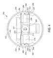
- FIG. 4 is an end view of the electronics subassembly shown in FIG. 3 .
- FIG. 5 is a perspective view of a portion of the leadless pacemaker shown in FIG. 2 .
- a leadless pacemaker includes a battery subassembly, a feedthrough subassembly, and an electronics subassembly coupled between the battery subassembly and the feedthrough subassembly.
- the electronics subassembly includes an electronics package, and a housing configured to provide a hermetic seal and comprising a first retaining feature and a second retaining feature configured to secure the electronics package within the housing.
- cardiac pacing is provided without a pulse generator located in the pectoral region or abdomen, without an electrode-lead separate from the pulse generator, without a communication coil or antenna, and without an additional requirement on battery power for transmitted communication.
- An embodiment of a cardiac pacing system configured to attain these characteristics includes a leadless cardiac pacemaker that is substantially enclosed in a hermetic housing suitable for placement on or attachment to the inside or outside of a cardiac chamber.
- the pacemaker can have two or more electrodes located within, on, or near the housing, for delivering pacing pulses to muscle of the cardiac chamber and optionally for sensing electrical activity from the muscle, and for bidirectional communication with at least one other device within or outside the body.
- the housing may include contain a primary battery to provide power for pacing, sensing, and communication, for example bidirectional communication.
- the housing may optionally contain circuits for sensing cardiac activity from the electrodes.
- the housing contains circuits for receiving information from at least one other device via the electrodes and contains circuits for generating pacing pulses for delivery via the electrodes.
- the housing can optionally contain circuits for transmitting information to at least one other device via the electrodes and can optionally contain circuits for monitoring device health.
- the housing contains circuits for controlling these operations in a predetermined manner.
- a cardiac pacemaker can be adapted for delivery and implantation into tissue in the human body.
- a leadless cardiac pacemaker can be adapted for implantation adjacent to heart tissue on the inside or outside wall of a cardiac chamber, using two or more electrodes located on or within the housing of the pacemaker, for pacing the cardiac chamber upon receiving a triggering signal from at least one other device within the body.
- Self-contained or leadless pacemakers or other biostimulators are typically fixed to an intracardial implant site by using a screw or helical member that screws into the myocardium. In case of malfunction, it is highly desirable to be able to retrieve the leadless pacemaker of biostimulators both acutely (during the implantation procedure) or chronically, after a period of time post implantation minimally invasively.
- leadless cardiac pacemaker includes a hermetic housing 102 with electrodes 104 and 106 disposed thereon. As shown, electrode 106 can be separated from but surrounded partially by a fixation mechanism 105 , and the 104 can be disposed on the housing 102 .
- Fixation mechanism 105 can be a fixation helix, a plurality of hooks, barbs, or other attaching features configured to attach the pacemaker to tissue, such as heart tissue.
- Hermetic housing 102 can also include an electronics compartment 110 within the housing that contains the electronic components necessary for operation of the pacemaker, including, for example, a pulse generator, communication electronics, a battery, and a processor for operation.
- Hermetic housing 102 can be adapted to be implanted on or in a human heart, and can be cylindrically shaped, rectangular, spherical, or any other appropriate shapes, for example.
- Hermetic housing 102 may be manufactured from a conductive, biocompatible, inert, and anodically safe material such as titanium, 316L stainless steel, or other similar materials. Hermetic housing 102 can further comprise an insulator disposed on the conductive material to separate electrodes 104 and 106 .
- the insulator can be an insulative coating on a portion of the housing between the electrodes, and can comprise materials such as silicone, polyurethane, parylene, or another biocompatible electrical insulator commonly used for implantable medical devices.
- a single insulator 108 is disposed along the portion of hermetic housing 102 between electrodes 104 and 106 .
- hermetic housing 102 itself may be an insulator instead of a conductor, such as an alumina ceramic or other similar materials, and electrodes 104 and 106 may be disposed upon hermetic housing 102 .
- pacemaker 100 may include a header assembly 112 to isolate electrode 104 from electrode 106 .
- Header assembly 112 may be made from PEEK, tecothane or another biocompatible plastic, and can contain a ceramic to metal feedthrough, a glass to metal feedthrough, or other any other appropriate feedthrough insulator as known in the art.
- FIG. 2 is a perspective view of a portion of a pacemaker 200 , such as pacemaker 100 .
- Pacemaker 200 includes an electronics subassembly 202 , a feedthrough subassembly 204 , and a battery subassembly 206 .
- electronics subassembly 202 is coupled between feedthrough subassembly 204 and battery subassembly 206 .
- Electronics subassembly 202 houses an electronics package 208 , as described herein.
- FIG. 3 is a perspective view of electronics subassembly 202
- FIG. 4 is an end view of electronics subassembly 202
- electronics subassembly 202 includes electronics package 208 positioned within a nose cone, or housing 210 .
- Housing 210 extends from a first end 211 to a second end 213 , and provides a hermetic seal for electronics package 208 .
- Housing 210 couples to feedthrough subassembly 204 at first end 211 , and couples to battery subassembly 206 at second end 213 .
- electronics package 208 includes a plurality of components coupled to a first circuit board 212 and a second circuit board 214 .
- First circuit board 212 and second circuit board 214 are connected to each other through a pair of flexible bands 216 .
- flexible bands 216 enable first and second circuit boards 212 and 214 to be folded over one another.
- flexible bands 216 have at least some resilience such that when first and second circuit boards 212 and 214 are folded over one another, first and second circuit boards 212 and 214 are biased to unfold from one another. This facilitates securing electronics package 208 in housing 210 , as described herein.
- housing 210 is substantially annular and includes a radially inner surface 220 and a radially outer surface 222 .
- a first retaining feature 224 and a second retaining feature 226 extend radially inward from radially inner surface 220 .
- First and second retaining features 224 are located diametrically opposite one another, and facilitate retaining electronics package 208 in housing 210 , as described herein.
- First retaining feature 224 defines a first groove 230
- second retaining feature 226 defines a second groove 232 .
- first groove 230 is defined by a first upper wall 234 , a first lower wall 236 , and a first side wall 238 extending between first upper wall 234 and first lower wall 236 .
- second groove 232 is defined by a second upper wall 240 , a second lower wall 242 , and a second side wall 244 extending between second upper wall 240 and second lower wall 242 .
- first and second grooves 230 and 232 extend along an entire length of housing 210 (i.e., from first end 211 to second end 213 ).
- first and second grooves 230 and 232 may only extend along a portion of the length of housing 210 .
- first and second circuit boards 212 and 214 are folded over one another and inserted into housing 210 .
- first and second circuit boards 212 and 214 are inserted into housing 210 such that a first edge 250 of first circuit board 212 and a first edge 252 of second circuit board 214 are received within first groove 230 , and such that a second edge 254 of first circuit board 212 and a second edge 256 of second circuit board 214 are received within second groove 232 .
- first and second circuit boards 212 and 214 due to the biasing force provided by flexible bands 216 , attempt to unfold relative to one another. Accordingly, first circuit board first edge 250 is biased against first upper wall 234 , first circuit board second edge 254 is biased against second upper wall 240 , second circuit board first edge 252 is biased against first lower wall 236 , and second circuit board second edge 256 is biased against second lower wall 242 .
- the biasing of first and second circuit boards 212 and 214 against upper and lower walls 234 , 240 , 236 , and 242 facilitates securing electronics package 208 within housing 210 .
- first circuit board first edge 250 and first circuit board second edge 254 each include an offset portion 260 . Offset portions 260 contact first and second side walls 238 and 244 .
- electronics package 208 includes a feedthrough connector 261 (e.g., a spring connector) for connecting feedthrough subassembly 204 to electronics subassembly 202 . Further, electronics package 208 includes a pair of battery connectors 262 (e.g., spring connectors) for connecting battery subassembly 206 to electronics subassembly 202 .
- a feedthrough connector 261 e.g., a spring connector
- battery connectors 262 e.g., spring connectors
- FIG. 5 is a perspective view of a portion of pacemaker 200 .
- a wire 270 extends from feedthrough connector 261 to an electrode 106 to facilitate coupling electronics subassembly 202 to feedthrough subassembly 204 .
- electronics subassembly 202 is coupled to battery subassembly 206 using battery connectors 262 and a coupling ring 272 .
- Using connectors 261 and 262 for the coupling between electronics subassembly 202 and feedthrough and battery subassemblies 204 and 206 facilitates simplifying the manufacturing and reducing the cost of pacemaker 200 .
- electronics subassembly 202 may be coupled to feedthrough subassembly 204 and battery subassembly 206 using any suitable techniques.
- electronics subassembly 202 is coupled to feedthrough subassembly 204 via welding (e.g., laser welding).
- housing 210 includes a protective band 280 , shown best in FIG. 3 .
- Protective band 280 is a machined annular component positioned at first end 211 of housing 210 .
- protective band 280 is integrally formed as part of housing 210 .
- protective band 280 may be a separate component coupled to housing 210 .
- At least some known leadless pacemakers include a metallic frame positioned within a housing, or nose cone.
- the metallic frame facilitates securing electronics within the housing and protecting the electronics from welding damage.
- the systems and methods described herein provide a housing having retaining features formed thereon for securing an electronics package. Accordingly, the systems and methods described herein eliminate the need for a separate, metallic frame, simplifying the manufacturing and reducing the cost of a leadless pacemaker. Further, in at least some embodiments, the leadless pacemaker described herein includes connectors that eliminate the need to weld components together.
- joinder references do not necessarily infer that two elements are directly connected and in fixed relation to each other. It is intended that all matter contained in the above description or shown in the accompanying drawings shall be interpreted as illustrative only and not limiting. Changes in detail or structure may be made without departing from the spirit of the disclosure as defined in the appended claims.
Landscapes
- Health & Medical Sciences (AREA)
- Cardiology (AREA)
- Radiology & Medical Imaging (AREA)
- Engineering & Computer Science (AREA)
- Biomedical Technology (AREA)
- Nuclear Medicine, Radiotherapy & Molecular Imaging (AREA)
- Life Sciences & Earth Sciences (AREA)
- Animal Behavior & Ethology (AREA)
- General Health & Medical Sciences (AREA)
- Public Health (AREA)
- Veterinary Medicine (AREA)
- Heart & Thoracic Surgery (AREA)
- Vascular Medicine (AREA)
- Electrotherapy Devices (AREA)
Abstract
Description
- (1) U.S. Pat. No. 8,457,742;
- (2) U.S. Published Application No. 2007/0088396A1;
- (3) U.S. Published Application 200710088397A1;
- (4) U.S. Pat. No. 8,352,025;
- (5) U.S. Pat. No. 7,937,148;
- (6) U.S. Pat. No. 7,945,333;
- (7) U.S. Pat. No. 8,010,209; and
- (8) Intl Publication WO/2007/047681A2.
Claims (12)
Priority Applications (1)
| Application Number | Priority Date | Filing Date | Title |
|---|---|---|---|
| US14/681,969 US9855435B2 (en) | 2015-04-08 | 2015-04-08 | Systems and methods for leadless pacemaker electronics assemblies |
Applications Claiming Priority (1)
| Application Number | Priority Date | Filing Date | Title |
|---|---|---|---|
| US14/681,969 US9855435B2 (en) | 2015-04-08 | 2015-04-08 | Systems and methods for leadless pacemaker electronics assemblies |
Publications (2)
| Publication Number | Publication Date |
|---|---|
| US20160296760A1 US20160296760A1 (en) | 2016-10-13 |
| US9855435B2 true US9855435B2 (en) | 2018-01-02 |
Family
ID=57112389
Family Applications (1)
| Application Number | Title | Priority Date | Filing Date |
|---|---|---|---|
| US14/681,969 Active 2035-10-20 US9855435B2 (en) | 2015-04-08 | 2015-04-08 | Systems and methods for leadless pacemaker electronics assemblies |
Country Status (1)
| Country | Link |
|---|---|
| US (1) | US9855435B2 (en) |
Cited By (39)
| Publication number | Priority date | Publication date | Assignee | Title |
|---|---|---|---|---|
| US10029107B1 (en) | 2017-01-26 | 2018-07-24 | Cardiac Pacemakers, Inc. | Leadless device with overmolded components |
| US10328272B2 (en) | 2016-05-10 | 2019-06-25 | Cardiac Pacemakers, Inc. | Retrievability for implantable medical devices |
| US10350423B2 (en) | 2016-02-04 | 2019-07-16 | Cardiac Pacemakers, Inc. | Delivery system with force sensor for leadless cardiac device |
| US10391319B2 (en) | 2016-08-19 | 2019-08-27 | Cardiac Pacemakers, Inc. | Trans septal implantable medical device |
| US10413733B2 (en) | 2016-10-27 | 2019-09-17 | Cardiac Pacemakers, Inc. | Implantable medical device with gyroscope |
| US10426962B2 (en) | 2016-07-07 | 2019-10-01 | Cardiac Pacemakers, Inc. | Leadless pacemaker using pressure measurements for pacing capture verification |
| US10434314B2 (en) | 2016-10-27 | 2019-10-08 | Cardiac Pacemakers, Inc. | Use of a separate device in managing the pace pulse energy of a cardiac pacemaker |
| US10434317B2 (en) | 2016-10-31 | 2019-10-08 | Cardiac Pacemakers, Inc. | Systems and methods for activity level pacing |
| US10463305B2 (en) | 2016-10-27 | 2019-11-05 | Cardiac Pacemakers, Inc. | Multi-device cardiac resynchronization therapy with timing enhancements |
| US10512784B2 (en) | 2016-06-27 | 2019-12-24 | Cardiac Pacemakers, Inc. | Cardiac therapy system using subcutaneously sensed P-waves for resynchronization pacing management |
| US10561330B2 (en) | 2016-10-27 | 2020-02-18 | Cardiac Pacemakers, Inc. | Implantable medical device having a sense channel with performance adjustment |
| US10583301B2 (en) | 2016-11-08 | 2020-03-10 | Cardiac Pacemakers, Inc. | Implantable medical device for atrial deployment |
| US10617874B2 (en) | 2016-10-31 | 2020-04-14 | Cardiac Pacemakers, Inc. | Systems and methods for activity level pacing |
| US10632313B2 (en) | 2016-11-09 | 2020-04-28 | Cardiac Pacemakers, Inc. | Systems, devices, and methods for setting cardiac pacing pulse parameters for a cardiac pacing device |
| US10688304B2 (en) | 2016-07-20 | 2020-06-23 | Cardiac Pacemakers, Inc. | Method and system for utilizing an atrial contraction timing fiducial in a leadless cardiac pacemaker system |
| US10737102B2 (en) | 2017-01-26 | 2020-08-11 | Cardiac Pacemakers, Inc. | Leadless implantable device with detachable fixation |
| US10758737B2 (en) | 2016-09-21 | 2020-09-01 | Cardiac Pacemakers, Inc. | Using sensor data from an intracardially implanted medical device to influence operation of an extracardially implantable cardioverter |
| US10758724B2 (en) | 2016-10-27 | 2020-09-01 | Cardiac Pacemakers, Inc. | Implantable medical device delivery system with integrated sensor |
| US10765871B2 (en) | 2016-10-27 | 2020-09-08 | Cardiac Pacemakers, Inc. | Implantable medical device with pressure sensor |
| US10780278B2 (en) | 2016-08-24 | 2020-09-22 | Cardiac Pacemakers, Inc. | Integrated multi-device cardiac resynchronization therapy using P-wave to pace timing |
| US10821288B2 (en) | 2017-04-03 | 2020-11-03 | Cardiac Pacemakers, Inc. | Cardiac pacemaker with pacing pulse energy adjustment based on sensed heart rate |
| US10835753B2 (en) | 2017-01-26 | 2020-11-17 | Cardiac Pacemakers, Inc. | Intra-body device communication with redundant message transmission |
| US10870008B2 (en) | 2016-08-24 | 2020-12-22 | Cardiac Pacemakers, Inc. | Cardiac resynchronization using fusion promotion for timing management |
| US10874861B2 (en) | 2018-01-04 | 2020-12-29 | Cardiac Pacemakers, Inc. | Dual chamber pacing without beat-to-beat communication |
| US10894163B2 (en) | 2016-11-21 | 2021-01-19 | Cardiac Pacemakers, Inc. | LCP based predictive timing for cardiac resynchronization |
| US10905889B2 (en) | 2016-09-21 | 2021-02-02 | Cardiac Pacemakers, Inc. | Leadless stimulation device with a housing that houses internal components of the leadless stimulation device and functions as the battery case and a terminal of an internal battery |
| US10905872B2 (en) | 2017-04-03 | 2021-02-02 | Cardiac Pacemakers, Inc. | Implantable medical device with a movable electrode biased toward an extended position |
| US10918875B2 (en) | 2017-08-18 | 2021-02-16 | Cardiac Pacemakers, Inc. | Implantable medical device with a flux concentrator and a receiving coil disposed about the flux concentrator |
| US10994145B2 (en) | 2016-09-21 | 2021-05-04 | Cardiac Pacemakers, Inc. | Implantable cardiac monitor |
| US11052258B2 (en) | 2017-12-01 | 2021-07-06 | Cardiac Pacemakers, Inc. | Methods and systems for detecting atrial contraction timing fiducials within a search window from a ventricularly implanted leadless cardiac pacemaker |
| US11065459B2 (en) | 2017-08-18 | 2021-07-20 | Cardiac Pacemakers, Inc. | Implantable medical device with pressure sensor |
| US11071870B2 (en) | 2017-12-01 | 2021-07-27 | Cardiac Pacemakers, Inc. | Methods and systems for detecting atrial contraction timing fiducials and determining a cardiac interval from a ventricularly implanted leadless cardiac pacemaker |
| US11185703B2 (en) | 2017-11-07 | 2021-11-30 | Cardiac Pacemakers, Inc. | Leadless cardiac pacemaker for bundle of his pacing |
| US11207527B2 (en) | 2016-07-06 | 2021-12-28 | Cardiac Pacemakers, Inc. | Method and system for determining an atrial contraction timing fiducial in a leadless cardiac pacemaker system |
| US11207532B2 (en) | 2017-01-04 | 2021-12-28 | Cardiac Pacemakers, Inc. | Dynamic sensing updates using postural input in a multiple device cardiac rhythm management system |
| US11235163B2 (en) | 2017-09-20 | 2022-02-01 | Cardiac Pacemakers, Inc. | Implantable medical device with multiple modes of operation |
| US11260216B2 (en) | 2017-12-01 | 2022-03-01 | Cardiac Pacemakers, Inc. | Methods and systems for detecting atrial contraction timing fiducials during ventricular filling from a ventricularly implanted leadless cardiac pacemaker |
| US11529523B2 (en) | 2018-01-04 | 2022-12-20 | Cardiac Pacemakers, Inc. | Handheld bridge device for providing a communication bridge between an implanted medical device and a smartphone |
| US11813463B2 (en) | 2017-12-01 | 2023-11-14 | Cardiac Pacemakers, Inc. | Leadless cardiac pacemaker with reversionary behavior |
Families Citing this family (12)
| Publication number | Priority date | Publication date | Assignee | Title |
|---|---|---|---|---|
| US10610693B2 (en) | 2013-07-11 | 2020-04-07 | Newpace Ltd. | Battery and electronics integration in a flexible implantable medical device |
| US20170100597A1 (en) * | 2015-10-12 | 2017-04-13 | Medtronic, Inc. | Sealed implantable medical device and method of forming same |
| WO2019108787A1 (en) | 2017-11-29 | 2019-06-06 | Medtronic, Inc. | Tissue conduction communication between devices |
| CN111417431B (en) | 2017-11-29 | 2024-08-06 | 美敦力公司 | Tissue conduction communication using a ramped drive signal |
| US11110279B2 (en) | 2017-11-29 | 2021-09-07 | Medtronic, Inc. | Signal transmission optimization for tissue conduction communication |
| CN111417434B (en) | 2017-11-29 | 2024-09-17 | 美敦力公司 | Device and method for reducing artifacts from tissue-conducted communication emissions |
| US11229796B2 (en) | 2017-12-15 | 2022-01-25 | Medtronic Inc. | Device, system and method with adaptive timing for tissue conduction communication transmission |
| US10918874B2 (en) | 2018-06-28 | 2021-02-16 | Medtronic, Inc. | Sealed package and method of forming same |
| EP3813928B1 (en) * | 2018-06-29 | 2023-08-09 | Saluda Medical Pty Ltd | Implantable neural stimulation device with two headers |
| US11071872B2 (en) | 2019-01-07 | 2021-07-27 | Pacesetter, Inc. | Systems and methods for performing pacing using multiple leadless pacemakers |
| US11097113B2 (en) | 2019-01-07 | 2021-08-24 | Pacesetter, Inc. | Systems and methods for performing pacing using leadless pacemakers |
| US11883673B2 (en) * | 2019-10-29 | 2024-01-30 | Medtronic, Inc. | Electronics assembly for implantable medical device |
Citations (5)
| Publication number | Priority date | Publication date | Assignee | Title |
|---|---|---|---|---|
| US20070088396A1 (en) | 2005-10-14 | 2007-04-19 | Jacobson Peter M | Leadless cardiac pacemaker |
| US20100305629A1 (en) * | 2009-05-29 | 2010-12-02 | Lund Jeffrey S | Elongate battery for implantable medical device |
| US20110190842A1 (en) * | 2010-01-29 | 2011-08-04 | Medtronic, Inc. | Implantable medical device battery |
| US20120151758A1 (en) * | 2010-12-20 | 2012-06-21 | Biotronik Se & Co. Kg | In-Situ Fold-Assisting Frame for Flexible Substrates |
| US20130123875A1 (en) * | 2011-11-04 | 2013-05-16 | Eric Varady | Leadless Cardiac Pacemaker with Integral Battery and Redundant Welds |
-
2015
- 2015-04-08 US US14/681,969 patent/US9855435B2/en active Active
Patent Citations (13)
| Publication number | Priority date | Publication date | Assignee | Title |
|---|---|---|---|---|
| US7945333B2 (en) | 2005-10-14 | 2011-05-17 | Nanostim, Inc. | Programmer for biostimulator system |
| US20070088397A1 (en) | 2005-10-14 | 2007-04-19 | Jacobson Peter M | Leadless cardiac pacemaker system with conductive communication |
| WO2007047681A2 (en) | 2005-10-14 | 2007-04-26 | Nanostim, Inc. | Leadless cardiac pacemaker and system |
| WO2007047681A3 (en) | 2005-10-14 | 2008-09-25 | Nanostim Inc | Leadless cardiac pacemaker and system |
| US7937148B2 (en) | 2005-10-14 | 2011-05-03 | Nanostim, Inc. | Rate responsive leadless cardiac pacemaker |
| US20070088396A1 (en) | 2005-10-14 | 2007-04-19 | Jacobson Peter M | Leadless cardiac pacemaker |
| US8010209B2 (en) | 2005-10-14 | 2011-08-30 | Nanostim, Inc. | Delivery system for implantable biostimulator |
| US8352025B2 (en) | 2005-10-14 | 2013-01-08 | Nanostim, Inc. | Leadless cardiac pacemaker triggered by conductive communication |
| US8457742B2 (en) | 2005-10-14 | 2013-06-04 | Nanostim, Inc. | Leadless cardiac pacemaker system for usage in combination with an implantable cardioverter-defibrillator |
| US20100305629A1 (en) * | 2009-05-29 | 2010-12-02 | Lund Jeffrey S | Elongate battery for implantable medical device |
| US20110190842A1 (en) * | 2010-01-29 | 2011-08-04 | Medtronic, Inc. | Implantable medical device battery |
| US20120151758A1 (en) * | 2010-12-20 | 2012-06-21 | Biotronik Se & Co. Kg | In-Situ Fold-Assisting Frame for Flexible Substrates |
| US20130123875A1 (en) * | 2011-11-04 | 2013-05-16 | Eric Varady | Leadless Cardiac Pacemaker with Integral Battery and Redundant Welds |
Cited By (44)
| Publication number | Priority date | Publication date | Assignee | Title |
|---|---|---|---|---|
| US10350423B2 (en) | 2016-02-04 | 2019-07-16 | Cardiac Pacemakers, Inc. | Delivery system with force sensor for leadless cardiac device |
| US10328272B2 (en) | 2016-05-10 | 2019-06-25 | Cardiac Pacemakers, Inc. | Retrievability for implantable medical devices |
| US10512784B2 (en) | 2016-06-27 | 2019-12-24 | Cardiac Pacemakers, Inc. | Cardiac therapy system using subcutaneously sensed P-waves for resynchronization pacing management |
| US11497921B2 (en) | 2016-06-27 | 2022-11-15 | Cardiac Pacemakers, Inc. | Cardiac therapy system using subcutaneously sensed p-waves for resynchronization pacing management |
| US11207527B2 (en) | 2016-07-06 | 2021-12-28 | Cardiac Pacemakers, Inc. | Method and system for determining an atrial contraction timing fiducial in a leadless cardiac pacemaker system |
| US10426962B2 (en) | 2016-07-07 | 2019-10-01 | Cardiac Pacemakers, Inc. | Leadless pacemaker using pressure measurements for pacing capture verification |
| US10688304B2 (en) | 2016-07-20 | 2020-06-23 | Cardiac Pacemakers, Inc. | Method and system for utilizing an atrial contraction timing fiducial in a leadless cardiac pacemaker system |
| US10391319B2 (en) | 2016-08-19 | 2019-08-27 | Cardiac Pacemakers, Inc. | Trans septal implantable medical device |
| US10870008B2 (en) | 2016-08-24 | 2020-12-22 | Cardiac Pacemakers, Inc. | Cardiac resynchronization using fusion promotion for timing management |
| US11464982B2 (en) | 2016-08-24 | 2022-10-11 | Cardiac Pacemakers, Inc. | Integrated multi-device cardiac resynchronization therapy using p-wave to pace timing |
| US10780278B2 (en) | 2016-08-24 | 2020-09-22 | Cardiac Pacemakers, Inc. | Integrated multi-device cardiac resynchronization therapy using P-wave to pace timing |
| US10758737B2 (en) | 2016-09-21 | 2020-09-01 | Cardiac Pacemakers, Inc. | Using sensor data from an intracardially implanted medical device to influence operation of an extracardially implantable cardioverter |
| US10994145B2 (en) | 2016-09-21 | 2021-05-04 | Cardiac Pacemakers, Inc. | Implantable cardiac monitor |
| US10905889B2 (en) | 2016-09-21 | 2021-02-02 | Cardiac Pacemakers, Inc. | Leadless stimulation device with a housing that houses internal components of the leadless stimulation device and functions as the battery case and a terminal of an internal battery |
| US10758724B2 (en) | 2016-10-27 | 2020-09-01 | Cardiac Pacemakers, Inc. | Implantable medical device delivery system with integrated sensor |
| US10463305B2 (en) | 2016-10-27 | 2019-11-05 | Cardiac Pacemakers, Inc. | Multi-device cardiac resynchronization therapy with timing enhancements |
| US10765871B2 (en) | 2016-10-27 | 2020-09-08 | Cardiac Pacemakers, Inc. | Implantable medical device with pressure sensor |
| US10434314B2 (en) | 2016-10-27 | 2019-10-08 | Cardiac Pacemakers, Inc. | Use of a separate device in managing the pace pulse energy of a cardiac pacemaker |
| US10561330B2 (en) | 2016-10-27 | 2020-02-18 | Cardiac Pacemakers, Inc. | Implantable medical device having a sense channel with performance adjustment |
| US10413733B2 (en) | 2016-10-27 | 2019-09-17 | Cardiac Pacemakers, Inc. | Implantable medical device with gyroscope |
| US11305125B2 (en) | 2016-10-27 | 2022-04-19 | Cardiac Pacemakers, Inc. | Implantable medical device with gyroscope |
| US10617874B2 (en) | 2016-10-31 | 2020-04-14 | Cardiac Pacemakers, Inc. | Systems and methods for activity level pacing |
| US10434317B2 (en) | 2016-10-31 | 2019-10-08 | Cardiac Pacemakers, Inc. | Systems and methods for activity level pacing |
| US10583301B2 (en) | 2016-11-08 | 2020-03-10 | Cardiac Pacemakers, Inc. | Implantable medical device for atrial deployment |
| US10632313B2 (en) | 2016-11-09 | 2020-04-28 | Cardiac Pacemakers, Inc. | Systems, devices, and methods for setting cardiac pacing pulse parameters for a cardiac pacing device |
| US10894163B2 (en) | 2016-11-21 | 2021-01-19 | Cardiac Pacemakers, Inc. | LCP based predictive timing for cardiac resynchronization |
| US11207532B2 (en) | 2017-01-04 | 2021-12-28 | Cardiac Pacemakers, Inc. | Dynamic sensing updates using postural input in a multiple device cardiac rhythm management system |
| US10029107B1 (en) | 2017-01-26 | 2018-07-24 | Cardiac Pacemakers, Inc. | Leadless device with overmolded components |
| US10835753B2 (en) | 2017-01-26 | 2020-11-17 | Cardiac Pacemakers, Inc. | Intra-body device communication with redundant message transmission |
| US10737102B2 (en) | 2017-01-26 | 2020-08-11 | Cardiac Pacemakers, Inc. | Leadless implantable device with detachable fixation |
| US11590353B2 (en) | 2017-01-26 | 2023-02-28 | Cardiac Pacemakers, Inc. | Intra-body device communication with redundant message transmission |
| US10821288B2 (en) | 2017-04-03 | 2020-11-03 | Cardiac Pacemakers, Inc. | Cardiac pacemaker with pacing pulse energy adjustment based on sensed heart rate |
| US10905872B2 (en) | 2017-04-03 | 2021-02-02 | Cardiac Pacemakers, Inc. | Implantable medical device with a movable electrode biased toward an extended position |
| US11065459B2 (en) | 2017-08-18 | 2021-07-20 | Cardiac Pacemakers, Inc. | Implantable medical device with pressure sensor |
| US10918875B2 (en) | 2017-08-18 | 2021-02-16 | Cardiac Pacemakers, Inc. | Implantable medical device with a flux concentrator and a receiving coil disposed about the flux concentrator |
| US12151116B2 (en) | 2017-08-18 | 2024-11-26 | Cardiac Pacemakers, Inc. | Implantable medical device with pressure sensor |
| US11235163B2 (en) | 2017-09-20 | 2022-02-01 | Cardiac Pacemakers, Inc. | Implantable medical device with multiple modes of operation |
| US11185703B2 (en) | 2017-11-07 | 2021-11-30 | Cardiac Pacemakers, Inc. | Leadless cardiac pacemaker for bundle of his pacing |
| US11052258B2 (en) | 2017-12-01 | 2021-07-06 | Cardiac Pacemakers, Inc. | Methods and systems for detecting atrial contraction timing fiducials within a search window from a ventricularly implanted leadless cardiac pacemaker |
| US11260216B2 (en) | 2017-12-01 | 2022-03-01 | Cardiac Pacemakers, Inc. | Methods and systems for detecting atrial contraction timing fiducials during ventricular filling from a ventricularly implanted leadless cardiac pacemaker |
| US11071870B2 (en) | 2017-12-01 | 2021-07-27 | Cardiac Pacemakers, Inc. | Methods and systems for detecting atrial contraction timing fiducials and determining a cardiac interval from a ventricularly implanted leadless cardiac pacemaker |
| US11813463B2 (en) | 2017-12-01 | 2023-11-14 | Cardiac Pacemakers, Inc. | Leadless cardiac pacemaker with reversionary behavior |
| US11529523B2 (en) | 2018-01-04 | 2022-12-20 | Cardiac Pacemakers, Inc. | Handheld bridge device for providing a communication bridge between an implanted medical device and a smartphone |
| US10874861B2 (en) | 2018-01-04 | 2020-12-29 | Cardiac Pacemakers, Inc. | Dual chamber pacing without beat-to-beat communication |
Also Published As
| Publication number | Publication date |
|---|---|
| US20160296760A1 (en) | 2016-10-13 |
Similar Documents
| Publication | Publication Date | Title |
|---|---|---|
| US9855435B2 (en) | Systems and methods for leadless pacemaker electronics assemblies | |
| US9242102B2 (en) | Leadless pacemaker with radial fixation mechanism | |
| US10105535B2 (en) | Implantable stimulation capsule | |
| US3788329A (en) | Body implantable lead | |
| EP1469908B1 (en) | Apparatus for shielding against mri disturbances | |
| US8948883B2 (en) | Electrode assemblies and associated fixation members for implantable medical devices | |
| CN105492069B (en) | With improved conductive electrical communication without lead pacemaker | |
| US20150088155A1 (en) | Mechanical configurations for a multi-site leadless pacemaker | |
| US20030144719A1 (en) | Method and apparatus for shielding wire for MRI resistant electrode systems | |
| US7822484B1 (en) | MRI-compatible implantable lead having high impedance electrodes | |
| CN111344042B (en) | Systems and methods for making and using low profile control modules for electrical stimulation systems | |
| US20070123938A1 (en) | Magnetically coupled microstimulators | |
| US7289856B1 (en) | Medical electrical lead containing a pyroelectric material | |
| WO2002087689A1 (en) | Insulating member for a medical electrical lead | |
| CN103249454A (en) | Leadless pacemaker with anti-swivel construction | |
| CN112996556A (en) | Leaded electrical stimulation system | |
| US11497919B2 (en) | Communication amplification device comprising retention elements for an implantable capsule | |
| WO2021113843A1 (en) | Implantable endovascular, low profile intracardiac left atrial restraining devices for low energy atrial cardioversion, pacing and sensing | |
| WO2017004471A1 (en) | Left side single pass lead for la and lv sensing and pacing | |
| US10039922B2 (en) | Active implantable medical device comprising a connector-free capsule, permanently connected to a microlead | |
| US20200306540A1 (en) | Systems and methods for making and using a low-profile control module for an electrical stimulation system | |
| CN215135972U (en) | Implantable medical device |
Legal Events
| Date | Code | Title | Description |
|---|---|---|---|
| AS | Assignment |
Owner name: PACESETTER, INC., CALIFORNIA Free format text: ASSIGNMENT OF ASSIGNORS INTEREST;ASSIGNORS:SAHABI, KAVOUS;GARABED, AREES;SIGNING DATES FROM 20150407 TO 20150428;REEL/FRAME:035512/0104 |
|
| STCF | Information on status: patent grant |
Free format text: PATENTED CASE |
|
| MAFP | Maintenance fee payment |
Free format text: PAYMENT OF MAINTENANCE FEE, 4TH YEAR, LARGE ENTITY (ORIGINAL EVENT CODE: M1551); ENTITY STATUS OF PATENT OWNER: LARGE ENTITY Year of fee payment: 4 |
|
| MAFP | Maintenance fee payment |
Free format text: PAYMENT OF MAINTENANCE FEE, 8TH YEAR, LARGE ENTITY (ORIGINAL EVENT CODE: M1552); ENTITY STATUS OF PATENT OWNER: LARGE ENTITY Year of fee payment: 8 |