US9855355B2 - Method and device for plasma-treating hollow bodies - Google Patents

Method and device for plasma-treating hollow bodies Download PDF

Info

Publication number
US9855355B2
US9855355B2 US14/772,385 US201414772385A US9855355B2 US 9855355 B2 US9855355 B2 US 9855355B2 US 201414772385 A US201414772385 A US 201414772385A US 9855355 B2 US9855355 B2 US 9855355B2
Authority
US
United States
Prior art keywords
tube
external tube
external
plasma
internal
Prior art date
Legal status (The legal status is an assumption and is not a legal conclusion. Google has not performed a legal analysis and makes no representation as to the accuracy of the status listed.)
Expired - Fee Related
Application number
US14/772,385
Other versions
US20160008500A1 (en
Inventor
Joerg Ehlbeck
Manfred Stieber
Klaus-Dieter Weltmann
Current Assignee (The listed assignees may be inaccurate. Google has not performed a legal analysis and makes no representation or warranty as to the accuracy of the list.)
Leibniz Institut fuer Plasmaforschung und Technologie eV
Original Assignee
Leibniz Institut fuer Plasmaforschung und Technologie eV
Priority date (The priority date is an assumption and is not a legal conclusion. Google has not performed a legal analysis and makes no representation as to the accuracy of the date listed.)
Filing date
Publication date
Application filed by Leibniz Institut fuer Plasmaforschung und Technologie eV filed Critical Leibniz Institut fuer Plasmaforschung und Technologie eV
Assigned to INP GREIFSWALD - LEIBNIZ-INSTITUT FÜR PLASMAFORSCHUNG UND TECHNOLOGIE E. V. reassignment INP GREIFSWALD - LEIBNIZ-INSTITUT FÜR PLASMAFORSCHUNG UND TECHNOLOGIE E. V. ASSIGNMENT OF ASSIGNORS INTEREST (SEE DOCUMENT FOR DETAILS). Assignors: STIEBER, MANFRED, EHLBECK, JOERG, WELTMANN, KLAUS-DIETER
Publication of US20160008500A1 publication Critical patent/US20160008500A1/en
Application granted granted Critical
Publication of US9855355B2 publication Critical patent/US9855355B2/en
Expired - Fee Related legal-status Critical Current
Anticipated expiration legal-status Critical

Links

Images

Classifications

    • AHUMAN NECESSITIES
    • A61MEDICAL OR VETERINARY SCIENCE; HYGIENE
    • A61LMETHODS OR APPARATUS FOR STERILISING MATERIALS OR OBJECTS IN GENERAL; DISINFECTION, STERILISATION OR DEODORISATION OF AIR; CHEMICAL ASPECTS OF BANDAGES, DRESSINGS, ABSORBENT PADS OR SURGICAL ARTICLES; MATERIALS FOR BANDAGES, DRESSINGS, ABSORBENT PADS OR SURGICAL ARTICLES
    • A61L2/00Methods or apparatus for disinfecting or sterilising materials or objects other than foodstuffs or contact lenses; Accessories therefor
    • A61L2/02Methods or apparatus for disinfecting or sterilising materials or objects other than foodstuffs or contact lenses; Accessories therefor using physical phenomena
    • A61L2/14Plasma, i.e. ionised gases
    • AHUMAN NECESSITIES
    • A61MEDICAL OR VETERINARY SCIENCE; HYGIENE
    • A61LMETHODS OR APPARATUS FOR STERILISING MATERIALS OR OBJECTS IN GENERAL; DISINFECTION, STERILISATION OR DEODORISATION OF AIR; CHEMICAL ASPECTS OF BANDAGES, DRESSINGS, ABSORBENT PADS OR SURGICAL ARTICLES; MATERIALS FOR BANDAGES, DRESSINGS, ABSORBENT PADS OR SURGICAL ARTICLES
    • A61L2202/00Aspects relating to methods or apparatus for disinfecting or sterilising materials or objects
    • A61L2202/10Apparatus features
    • A61L2202/12Apparatus for isolating biocidal substances from the environment
    • A61L2202/121Sealings, e.g. doors, covers, valves, sluices
    • AHUMAN NECESSITIES
    • A61MEDICAL OR VETERINARY SCIENCE; HYGIENE
    • A61LMETHODS OR APPARATUS FOR STERILISING MATERIALS OR OBJECTS IN GENERAL; DISINFECTION, STERILISATION OR DEODORISATION OF AIR; CHEMICAL ASPECTS OF BANDAGES, DRESSINGS, ABSORBENT PADS OR SURGICAL ARTICLES; MATERIALS FOR BANDAGES, DRESSINGS, ABSORBENT PADS OR SURGICAL ARTICLES
    • A61L2202/00Aspects relating to methods or apparatus for disinfecting or sterilising materials or objects
    • A61L2202/10Apparatus features
    • A61L2202/12Apparatus for isolating biocidal substances from the environment
    • A61L2202/122Chambers for sterilisation
    • AHUMAN NECESSITIES
    • A61MEDICAL OR VETERINARY SCIENCE; HYGIENE
    • A61LMETHODS OR APPARATUS FOR STERILISING MATERIALS OR OBJECTS IN GENERAL; DISINFECTION, STERILISATION OR DEODORISATION OF AIR; CHEMICAL ASPECTS OF BANDAGES, DRESSINGS, ABSORBENT PADS OR SURGICAL ARTICLES; MATERIALS FOR BANDAGES, DRESSINGS, ABSORBENT PADS OR SURGICAL ARTICLES
    • A61L2202/00Aspects relating to methods or apparatus for disinfecting or sterilising materials or objects
    • A61L2202/20Targets to be treated
    • A61L2202/23Containers, e.g. vials, bottles, syringes, mail

Definitions

  • the present invention relates to a device for plasma-treating hollow bodies, such as bottles, vials, syringes, shut-off caps, etc., in particular with a view to sterilising said hollow bodies, and is equally suitable for various discharge types such as dielectric barrier discharge and discharges with high frequency and microwave excitation.
  • the core of the invention is a system consisting of three, preferably concentrically arranged, tubes (shells), wherein the inner shell serves as an internal conductor or respectively internal electrode, the middle shell represents the—sealed partially on the base plate—external conductor or respectively external electrode and the outer shell has a seal on the top end.
  • the device allows a pressure gradient to be set between the interior and the exterior of the object to be treated, which can be advantageously used for process control and plasma formation and forms the basis for an optimised in-line method of plasma treatment of hollow bodies.
  • Direct plasma methods at atmospheric pressure such as the use of high-frequency-excited plasma jets, fail in noble gas mode at the operating costs caused by the high gas consumption.
  • the service life drops on one hand and the gas temperature increases so that suitability for thermolabile materials is questionable.
  • Low-pressure reactors cause high investment costs through complex and—especially in the case of batch mode—large receptacles with high dead volumes.
  • the pump rates required at high throughput rates are another cost factor for investment and operation.
  • DE 199 16 479 A1 discloses a device for sterilising receptacles by means of plasma at a low pressure.
  • the described plasma concerns a high-frequency plasma.
  • An atmospheric pressure plasma or a dielectric barrier discharge is not described therein.
  • a sealing system, based on a preferably concentrically arranged double chamber, is also not subject matter of DE 199 16 479 A1.
  • the publication DE 10 2008 034 111 A1 describes a device for sterilising and/or disinfecting workpieces made of plastic, preferably closing caps under atmospheric pressure by means of a plasma.
  • a special type of a double-chamber system for generating high process gas purity is also not covered in this document.
  • the object of the invention is to eliminate the disadvantages of the solutions described in the state of the art.
  • the object was solved by a device for plasma-treating hollow bodies and a corresponding method.
  • An important characteristic of the invention is the first-time combination of the plasma process and sealing system. This is realized such that external tubes ( 4 , 6 ), of which at least one is electrically conductive, are connected to each other so as to be impermeable to gas, but galvanically insulated such that they form an antechamber between the two external tubes ( 4 , 6 ) and a treatment chamber between the external tube ( 6 ) and the internal tube ( 1 ).
  • FIG. 1 is a schematic illustration of a device for plasma treating hollow bodies, according to some embodiments of the present disclosure
  • FIG. 2 and FIG. 3 are schematic illustrations of using the device with an object, according to some embodiments of the present disclosure.
  • FIG. 4 and FIG. 5 are schematic illustrations of exemplary usage of the device connected to a gas, according to some embodiments of the present disclosure.
  • the present invention is suitable for different discharge types like DBD, high-frequency and microwave excitation. It describes a system of three preferably concentrically arranged tubes (shells).
  • the internal tube serves as internal conductor or respectively internal electrode
  • the middle tube represents the external conductor or the external electrode. It seals partially on the metallic transport plate.
  • the external shell has a seal on the top end. The goal is to direct the gas supply with slight overpressure through the gap between the external and middle shell. Leaks in the sealing system do not thereby lead to a contamination of the process gases. Gas flow and operating pressure can be set via the impermeability of the contact surface of the middle shell to the transport plate.
  • the free selection of the process gas as well as the reduction in the operating pressure make it possible to also operate using DBD vials with their typical shape with moderate voltages.
  • a rough centring of the vials on the device can take place through the lowering process.
  • the fine adjustment can take place in the lowered mode through injection of a not necessarily sterile tangential gas flow.
  • the individual device can be combined into corresponding beams. These can be moved along in parallel with the transport of the vials through transport chains on both sides.
  • the system can be adjusted for greatly differing variables. For this, a tool changing station and a tool magazine can be installed on the side facing the treatment location in order to thus perform a fully automated tool change.
  • FIGS. 1, 2, 3, 4 and 5 show the device according to the invention.
  • FIGS. 1, 2 and 3 The device according to a preferred embodiment of the invention is shown schematically in FIGS. 1, 2 and 3 .
  • the device has an electrically conductive internal tube [ 1 ], via which gases can be discharged or supplied.
  • openings in the tube e.g. at position [ 2 ] are used.
  • the internal tube [I] can serve as an internal electrode of a dielectric barrier discharge or as a coaxial internal conductor of a high-frequency or microwave supply. For this, it can also be provided with special structures in order to ensure a better ignition of the plasma.
  • the internal tube can be covered with a dielectric for additional insulation or for increasing the chemical durability.
  • the internal tube is galvanically insulated—preferably by a flange [ 3 ]—connected with two external tubes [ 4 , 6 ]. At least one of them is electrically conductive.
  • the two tubes can be at the same potential. It is particularly advantageous to set it on earth potential. Dielectric casings can also be used here.
  • the tube [ 6 ] can also be used as a further dielectric.
  • the electrically conductive external tube(s) then form the second electrode in the case of the operation as dielectric barrier discharge. In the case of a high-frequency or microwave excitation of the plasma, it represents the coaxial external conductor.
  • the dielectric required for a dielectric barrier discharge can also be represented by the object to be treated itself.
  • the device is pushed for treatment over the object to be treated (see FIGS. 4 and 5 ) and the external tube [ 4 ] contacts the preferably earthed base plate [ 8 ].
  • the most gas-impermeable connection possible is produced by a seal in [ 5 ].
  • the gap dimension from [ 6 ] to [ 8 ] can be varied.
  • An additional seal can also be installed for example in [ 6 ], and the gas supply can be achieved via bore holes through the walls. These can be regulated for example in that [ 6 ] is designed as two parts and the bore holes can be opened or respectively closed by twisting the two concentric tubes against each other.
  • the method and device are thus particularly suitable for a high number of load cycles.
  • the gas flow as well as the pressure areas can be reversed.
  • a tangential gas flow can be created, which leads to a centring of the object to be treated, through additional gas channels in [ 6 ] or respectively sloping grooves in the floor of [ 6 ] between [ 6 ] and the object to be treated.
  • a lifting of the object to be treated from the floor plate can be achieved, and a treatment of the outer floor area of the object to be treated can thus also be achieved.
  • Another option for lifting the object to be treated from the floor plate [ 8 ] can be achieved when the internal tube [ 1 ] or respectively parts of it can move in the case of a two-part design in relationship to the external tubes [ 4 ] and [ 6 ] such that the floor of the bottom can be suctioned via a corresponding device and the treatment product can then thus be lifted so that the bottom side can be treated.
  • a sealing effect between the object to be treated and the flange [ 3 ] can also be achieved through this method in the case of bottles and hollow bodies, which leads to a pressure gradient between the interior and exterior of the object to be treated and can be advantageously used for process control and plasma formation.

Landscapes

  • Health & Medical Sciences (AREA)
  • Animal Behavior & Ethology (AREA)
  • Plasma & Fusion (AREA)
  • Engineering & Computer Science (AREA)
  • Epidemiology (AREA)
  • Life Sciences & Earth Sciences (AREA)
  • Physics & Mathematics (AREA)
  • General Health & Medical Sciences (AREA)
  • Public Health (AREA)
  • Veterinary Medicine (AREA)
  • Apparatus For Disinfection Or Sterilisation (AREA)
  • Plasma Technology (AREA)
  • Physical Or Chemical Processes And Apparatus (AREA)

Abstract

An essential feature of the invention is the original combination of a plasma process and a sealing system. This is achieved with external tubes (4, 6), which are connected to each other so as to be impermeable to gas, but galvanically insulated, and of which at least one is electrically conductive, such that the external tubes form an antechamber between the two external tubes (4, 6) and a treatment chamber between the external tube (6) and the internal tube (1).

Description

DESCRIPTION OF THE INVENTION
The present invention relates to a device for plasma-treating hollow bodies, such as bottles, vials, syringes, shut-off caps, etc., in particular with a view to sterilising said hollow bodies, and is equally suitable for various discharge types such as dielectric barrier discharge and discharges with high frequency and microwave excitation. The core of the invention is a system consisting of three, preferably concentrically arranged, tubes (shells), wherein the inner shell serves as an internal conductor or respectively internal electrode, the middle shell represents the—sealed partially on the base plate—external conductor or respectively external electrode and the outer shell has a seal on the top end. The device allows a pressure gradient to be set between the interior and the exterior of the object to be treated, which can be advantageously used for process control and plasma formation and forms the basis for an optimised in-line method of plasma treatment of hollow bodies.
STATE OF THE ART
In particular in the pharmaceutical industry, there is a high demand for high-rate sterilisation methods for primarily small hollow bodies in the range of 2 to 100 ml. Typical examples of these are vials and syringes.
There is an increasing desire to replace classic thermal methods, although they have proven to be very safe methods, with modern methods. The anticipated main advantages are shorter process times, in particular the avoidance of cooling buffers, and the accompanying, more compact structure, or respectively a higher throughput with the same construction volume.
Methods of gas sterilisation, such as the use of ethylene oxide, formaldehyde or hydrogen peroxide, are problematic in their application and bear the risk of a negative interaction with the pharmaceutical preparation to be filled. Even plasma-based indirect methods like ozonation or the PPA method, which minimize risk of damage, are subject to this interaction risk.
Direct plasma methods at atmospheric pressure, such as the use of high-frequency-excited plasma jets, fail in noble gas mode at the operating costs caused by the high gas consumption. During transition to air mode, if technically implementable, the service life drops on one hand and the gas temperature increases so that suitability for thermolabile materials is questionable.
Another example of cold plasmas at atmospheric pressure is the DBE, which would however have to realize great clearances due to the shape of the hollow body. The high voltages required for this make an industrial application difficult.
Low-pressure reactors cause high investment costs through complex and—especially in the case of batch mode—large receptacles with high dead volumes. The pump rates required at high throughput rates are another cost factor for investment and operation.
The publications DE 199 16 479 A1 and DE 10 2008 034 111 A1 also belong to the state of the art. DE 199 16 479 A1 discloses a device for sterilising receptacles by means of plasma at a low pressure. The described plasma concerns a high-frequency plasma. An atmospheric pressure plasma or a dielectric barrier discharge is not described therein. A sealing system, based on a preferably concentrically arranged double chamber, is also not subject matter of DE 199 16 479 A1.
The publication DE 10 2008 034 111 A1 describes a device for sterilising and/or disinfecting workpieces made of plastic, preferably closing caps under atmospheric pressure by means of a plasma. Thus, a special type of a double-chamber system for generating high process gas purity is also not covered in this document.
None of the known technical solutions discloses an efficient cost-saving solution for generating defined process gas atmospheres in high-rate processes. These are essential for achieving stable process conditions. The smallest impurities can—in particular in the case of sterilization processes—lead to complete process failure.
The plasma generation methods listed in the named documents have already been the state of the art for years.
Object of the Invention
The object of the invention is to eliminate the disadvantages of the solutions described in the state of the art.
Solution of the Object
The object was solved by a device for plasma-treating hollow bodies and a corresponding method. An important characteristic of the invention is the first-time combination of the plasma process and sealing system. This is realized such that external tubes (4, 6), of which at least one is electrically conductive, are connected to each other so as to be impermeable to gas, but galvanically insulated such that they form an antechamber between the two external tubes (4, 6) and a treatment chamber between the external tube (6) and the internal tube (1).
BRIEF DESCRIPTION OF THE DRAWINGS
Some non-limiting exemplary embodiments or features of the disclosed subject matter are illustrated in the following drawings.
In the drawings:
FIG. 1 is a schematic illustration of a device for plasma treating hollow bodies, according to some embodiments of the present disclosure;
FIG. 2 and FIG. 3 are schematic illustrations of using the device with an object, according to some embodiments of the present disclosure; and
FIG. 4 and FIG. 5 are schematic illustrations of exemplary usage of the device connected to a gas, according to some embodiments of the present disclosure.
DESCRIPTION OF THE INVENTION
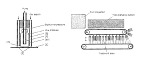
The present invention is suitable for different discharge types like DBD, high-frequency and microwave excitation. It describes a system of three preferably concentrically arranged tubes (shells). The internal tube serves as internal conductor or respectively internal electrode, and the middle tube represents the external conductor or the external electrode. It seals partially on the metallic transport plate. The external shell has a seal on the top end. The goal is to direct the gas supply with slight overpressure through the gap between the external and middle shell. Leaks in the sealing system do not thereby lead to a contamination of the process gases. Gas flow and operating pressure can be set via the impermeability of the contact surface of the middle shell to the transport plate. The free selection of the process gas as well as the reduction in the operating pressure make it possible to also operate using DBD vials with their typical shape with moderate voltages. A rough centring of the vials on the device can take place through the lowering process. The fine adjustment can take place in the lowered mode through injection of a not necessarily sterile tangential gas flow. The individual device can be combined into corresponding beams. These can be moved along in parallel with the transport of the vials through transport chains on both sides. By means of the tool change, the system can be adjusted for greatly differing variables. For this, a tool changing station and a tool magazine can be installed on the side facing the treatment location in order to thus perform a fully automated tool change.
The following main problems are thus solved by the invention:
  • 1. No use of complex vacuum reactors
  • 2. Minimization of dead volume, resulting in a reduction in pump performance
  • 3. The sealing problem is solved by the special gas supply
  • 4. Because of use in low to medium pressure, a broad bandwidth of process gasses can be used (e.g. air, noble gases, forming gas, addition of moisture . . . )
  • 5. Form tolerance is given
Compared to frequently used batch processes, one has the advantages of an in-line method. In addition, there is the advantage that the volume to be evacuated was minimized in the device, which leads on one hand to lower costs with respect to the evacuation process and minimizes the overall process times. Furthermore, the quantities of required process gases, in particular precursors during coating, are also reduced.
The advantage compared to classic in-line plasma processes is above all the reduced effort for the sealing system. Another important advantage is the increased process safety in the event of a failure of the sealing system.
EXEMPLARY EMBODIMENTS
The invention is explained in greater detail below based on a few examples without restricting the invention to these examples. FIGS. 1, 2, 3, 4 and 5 show the device according to the invention.
The following reference numbers are used for the below drawings:
  • [1] Electrically conductive internal tube (high-voltage electrode, suctioning)
  • [2] Openings in the internal tube
  • [3] Galvanic insulation through a flange
  • [4] External tube I
  • [5] Seal
  • [6] External tube II (earth electrode)
  • [7] Contact seal
  • [8] Base plate/floor plate/transport plate
  • [9] Opening for the supply of the working gas
  • [10] Object to be treated (hollow body)
The device according to a preferred embodiment of the invention is shown schematically in FIGS. 1, 2 and 3.
According to FIGS. 1 to 3, the device has an electrically conductive internal tube [1], via which gases can be discharged or supplied. For this, openings in the tube, e.g. at position [2], are used. The internal tube [I] can serve as an internal electrode of a dielectric barrier discharge or as a coaxial internal conductor of a high-frequency or microwave supply. For this, it can also be provided with special structures in order to ensure a better ignition of the plasma. The internal tube can be covered with a dielectric for additional insulation or for increasing the chemical durability. The internal tube is galvanically insulated—preferably by a flange [3]—connected with two external tubes [4, 6]. At least one of them is electrically conductive. The two tubes can be at the same potential. It is particularly advantageous to set it on earth potential. Dielectric casings can also be used here. The tube [6] can also be used as a further dielectric. The electrically conductive external tube(s) then form the second electrode in the case of the operation as dielectric barrier discharge. In the case of a high-frequency or microwave excitation of the plasma, it represents the coaxial external conductor. Furthermore, the dielectric required for a dielectric barrier discharge can also be represented by the object to be treated itself.
The device is pushed for treatment over the object to be treated (see FIGS. 4 and 5) and the external tube [4] contacts the preferably earthed base plate [8]. The most gas-impermeable connection possible is produced by a seal in [5].
Through a supply of the working gases through the openings [9] and exhaust of the gases through the openings [2] in the internal tube, a slight overpressure can be achieved at a corresponding gap width between [6] and [8] in the corresponding gas flow in the gap between [4] and [6]. In contrast, normal pressure to underpressure prevails in the treatment area between [6] and [1]. It is achieved through this operating method that the requirements of the sealing system [5, 7] are not high. If this seal fails, it does not lead to a contamination of the process gas and thus an accompanying process outage. The consequence of a seal failure is primarily the increased gas consumption, which is easy to detect and can be fixed.
In order to achieve an improved adjustment of the pressure ratios in the intermediate space between [4] and [6] and the treatment chamber between [1] and [6], the gap dimension from [6] to [8] can be varied. An additional seal can also be installed for example in [6], and the gas supply can be achieved via bore holes through the walls. These can be regulated for example in that [6] is designed as two parts and the bore holes can be opened or respectively closed by twisting the two concentric tubes against each other.
The method and device are thus particularly suitable for a high number of load cycles.
For flushing, e.g. to remove toxic gases forming in the process, the gas flow as well as the pressure areas can be reversed.
Additionally, a tangential gas flow can be created, which leads to a centring of the object to be treated, through additional gas channels in [6] or respectively sloping grooves in the floor of [6] between [6] and the object to be treated. Through an increase in the flow speed, a lifting of the object to be treated from the floor plate can be achieved, and a treatment of the outer floor area of the object to be treated can thus also be achieved.
Another option for lifting the object to be treated from the floor plate [8] can be achieved when the internal tube [1] or respectively parts of it can move in the case of a two-part design in relationship to the external tubes [4] and [6] such that the floor of the bottom can be suctioned via a corresponding device and the treatment product can then thus be lifted so that the bottom side can be treated.
A sealing effect between the object to be treated and the flange [3] can also be achieved through this method in the case of bottles and hollow bodies, which leads to a pressure gradient between the interior and exterior of the object to be treated and can be advantageously used for process control and plasma formation.

Claims (9)

The invention claimed is:
1. A device for plasma-treating hollow bodies (10), comprising a base plate (8), an electrically conductive internal tube (1) and, two external tubes (4, 6), namely an inner external tube (6) and an outer external tube (4), of which
at least the inner external tube (6) or the outer external tube (4) is electrically conductive,
wherein the inner external tube (6) and the outer external tube (4) are connected to each other so as to be impermeable to gas, such that an antechamber between the two external tubes (4, 6) is formed;
a plasma generating device for generating a plasma between the internal tube (1) and the inner external tube (6);
and a flange (3) between the internal tube (1) and the inner external tube (6), configured to form a treatment chamber between the inner external tube (6) and the internal tube (1);
wherein the internal tube (1) and the inner external tube (6) are galvanically insulated from each other by the flange (3);
and wherein the outer external tube (4) is connected or is connectable with the base plate (8) via a seal (5) and the inner external tube (6) is connected or is connectable with the base plate (8) via an adjustable contact seal (7).
2. The device according to claim 1, wherein the interior tube (1) has at least one opening (2) and the antechamber has at least one opening (9) for filling in or suctioning out gases.
3. The device according to claim 1, wherein the two external tubes (4, 6) and the base plate (8) are at a same potential.
4. The device according to claim 1, wherein the internal tube (1) and the two external tubes (4, 6) are arranged concentrically.
5. The device according to claim 1, wherein the internal tube functions as a high-voltage electrode in the case of a dielectric barrier discharge and is covered with a dielectric.
6. The device according to claim 1, wherein the inner external tube (6) serves as a dielectric.
7. The device according to claim 1, wherein the inner external tube (6) is designed as two parts and/or contains additional openings for gases and/or an additional seal.
8. The device according to claim 1, wherein the inner external tube (6) has additional gas channels and respectively sloping grooves in the base plate (8).
9. A beam system, comprising a plurality of devices, wherein each device from the plurality of devices is a device according to claim 1, wherein said plurality of devices are combined into beams, which can be moved along in parallel with a transport of vials by means of transport chains arranged for transporting the vials and said plurality of devices.
US14/772,385 2013-03-04 2014-03-04 Method and device for plasma-treating hollow bodies Expired - Fee Related US9855355B2 (en)

Applications Claiming Priority (4)

Application Number Priority Date Filing Date Title
DE102013203648.5A DE102013203648A1 (en) 2013-03-04 2013-03-04 METHOD AND DEVICE FOR PLASMA TREATMENT OF HOLLOW BODIES
DE102013203648 2013-03-04
DE102013203648.5 2013-03-04
PCT/EP2014/054166 WO2014135531A1 (en) 2013-03-04 2014-03-04 Method and device for plasma-treating hollow bodies

Publications (2)

Publication Number Publication Date
US20160008500A1 US20160008500A1 (en) 2016-01-14
US9855355B2 true US9855355B2 (en) 2018-01-02

Family

ID=50439328

Family Applications (1)

Application Number Title Priority Date Filing Date
US14/772,385 Expired - Fee Related US9855355B2 (en) 2013-03-04 2014-03-04 Method and device for plasma-treating hollow bodies

Country Status (4)

Country Link
US (1) US9855355B2 (en)
EP (1) EP2964274B1 (en)
DE (1) DE102013203648A1 (en)
WO (1) WO2014135531A1 (en)

Families Citing this family (3)

* Cited by examiner, † Cited by third party
Publication number Priority date Publication date Assignee Title
DE202009011521U1 (en) * 2009-08-25 2010-12-30 INP Greifswald Leibniz-Institut für Plasmaforschung und Technologie e. V. Plasma cuff
EP3171676B1 (en) * 2015-11-17 2020-06-24 Leibniz-Institut für Plasmaforschung und Technologie e.V. Plasma generating device, plasma generating system and method of generating plasma
TWI702032B (en) * 2019-06-06 2020-08-21 瀧儀生醫科技股份有限公司 Catheter treating device and method thereof

Citations (8)

* Cited by examiner, † Cited by third party
Publication number Priority date Publication date Assignee Title
US4221972A (en) * 1978-01-26 1980-09-09 Werner Oppel Apparatus for the partial treatment of elongated articles by current intensive glow discharge
US5216223A (en) * 1990-02-26 1993-06-01 Siegfried Straemke Plasma treatment apparatus
US5897831A (en) * 1987-02-25 1999-04-27 Adir Jacob Process for dry sterilization of medical devices and materials
DE19807742A1 (en) 1998-02-24 1999-10-21 Ruediger Haaga Gmbh Sterilization apparatus for mantle of metal cans
DE19916479A1 (en) 1999-04-13 2000-10-19 Ruediger Haaga Gmbh Sterilizing appliance for interior of bottle has chamber evacuated by pump and small gap between bottle and wall of chamber ensures that vacuum exists inside and outside bottle
EP2008670A1 (en) 2006-03-07 2008-12-31 University of The Ryukyus Sterilizer and sterilization method using the same
DE102008034111A1 (en) 2008-07-21 2010-01-28 Khs Ag Method and device for sterilizing and / or disinfecting
US7914692B2 (en) * 2006-08-29 2011-03-29 Ngk Insulators, Ltd. Methods of generating plasma, of etching an organic material film, of generating minus ions, of oxidation and nitriding

Patent Citations (8)

* Cited by examiner, † Cited by third party
Publication number Priority date Publication date Assignee Title
US4221972A (en) * 1978-01-26 1980-09-09 Werner Oppel Apparatus for the partial treatment of elongated articles by current intensive glow discharge
US5897831A (en) * 1987-02-25 1999-04-27 Adir Jacob Process for dry sterilization of medical devices and materials
US5216223A (en) * 1990-02-26 1993-06-01 Siegfried Straemke Plasma treatment apparatus
DE19807742A1 (en) 1998-02-24 1999-10-21 Ruediger Haaga Gmbh Sterilization apparatus for mantle of metal cans
DE19916479A1 (en) 1999-04-13 2000-10-19 Ruediger Haaga Gmbh Sterilizing appliance for interior of bottle has chamber evacuated by pump and small gap between bottle and wall of chamber ensures that vacuum exists inside and outside bottle
EP2008670A1 (en) 2006-03-07 2008-12-31 University of The Ryukyus Sterilizer and sterilization method using the same
US7914692B2 (en) * 2006-08-29 2011-03-29 Ngk Insulators, Ltd. Methods of generating plasma, of etching an organic material film, of generating minus ions, of oxidation and nitriding
DE102008034111A1 (en) 2008-07-21 2010-01-28 Khs Ag Method and device for sterilizing and / or disinfecting

Non-Patent Citations (2)

* Cited by examiner, † Cited by third party
Title
Searcht report issued for Priority Application-German Patent Application No. 10 2013 203 648.5, dated Aug. 7, 2014.
Searcht report issued for Priority Application—German Patent Application No. 10 2013 203 648.5, dated Aug. 7, 2014.

Also Published As

Publication number Publication date
WO2014135531A1 (en) 2014-09-12
EP2964274A1 (en) 2016-01-13
DE102013203648A1 (en) 2014-09-04
EP2964274B1 (en) 2021-05-05
US20160008500A1 (en) 2016-01-14

Similar Documents

Publication Publication Date Title
KR102861090B1 (en) Lift pin mechanism
TWI418263B (en) Plasma processing device
US9855355B2 (en) Method and device for plasma-treating hollow bodies
CN101533762B (en) Gate valve and semiconductor manufacturing apparatus
KR200491849Y1 (en) Load lock chamber with slit valve doors
KR102802107B1 (en) Plasma chamber with tandem processing regions
JP2000316954A (en) Method for exhausting in plasma sterilizing reactor
KR20100095427A (en) Method and apparatus for sealing an opening of a processing chamber
US20230130762A1 (en) Plasma generating apparatus and large-volume plasma treatment system
WO2009078361A1 (en) Plasma sterilizer
TW200715403A (en) Plasma processing apparatus
CN104378904B (en) A plasma chamber with a mechanism for generating negative hydrogen ions
US6037562A (en) Arrangement and process for sterilizing containers by means of low-pressure plasma
JP6446289B2 (en) Barrier film forming apparatus and barrier film forming method
US5801354A (en) Device for sterilizing the inner surfaces of pressure sensitive containers
TWI386355B (en) An insulating piping member, a gas supply device, and an ion beam device
US20210249238A1 (en) Exhaust pipe device
KR101114654B1 (en) Anodizing method of a plasma processing container
CN101721724A (en) Hydrogen peroxide plasma enhanced sterilizer
KR101926056B1 (en) Plasma sterlizer
JP6566686B2 (en) Equipment for film formation in containers
WO2007083480A1 (en) Plasma processing apparatus and semiconductor element manufactured by such apparatus
US20150292089A1 (en) Resin container coating device
CN217933708U (en) Ignition-preventing gas pipe and plasma processing device thereof
JP2008270493A (en) Plasma processing equipment

Legal Events

Date Code Title Description
AS Assignment

Owner name: INP GREIFSWALD - LEIBNIZ-INSTITUT FUER PLASMAFORSC

Free format text: ASSIGNMENT OF ASSIGNORS INTEREST;ASSIGNORS:EHLBECK, JOERG;STIEBER, MANFRED;WELTMANN, KLAUS-DIETER;SIGNING DATES FROM 20150831 TO 20150901;REEL/FRAME:036483/0334

STCF Information on status: patent grant

Free format text: PATENTED CASE

FEPP Fee payment procedure

Free format text: MAINTENANCE FEE REMINDER MAILED (ORIGINAL EVENT CODE: REM.); ENTITY STATUS OF PATENT OWNER: SMALL ENTITY

LAPS Lapse for failure to pay maintenance fees

Free format text: PATENT EXPIRED FOR FAILURE TO PAY MAINTENANCE FEES (ORIGINAL EVENT CODE: EXP.); ENTITY STATUS OF PATENT OWNER: SMALL ENTITY

STCH Information on status: patent discontinuation

Free format text: PATENT EXPIRED DUE TO NONPAYMENT OF MAINTENANCE FEES UNDER 37 CFR 1.362

FP Lapsed due to failure to pay maintenance fee

Effective date: 20220102