US9847307B1 - Two-end driving, high-frequency sub-substrate structure and high-frequency transmission structure including the same - Google Patents
Two-end driving, high-frequency sub-substrate structure and high-frequency transmission structure including the same Download PDFInfo
- Publication number
- US9847307B1 US9847307B1 US15/459,523 US201715459523A US9847307B1 US 9847307 B1 US9847307 B1 US 9847307B1 US 201715459523 A US201715459523 A US 201715459523A US 9847307 B1 US9847307 B1 US 9847307B1
- Authority
- US
- United States
- Prior art keywords
- pad area
- sub
- signal pad
- substrate
- grounding
- Prior art date
- Legal status (The legal status is an assumption and is not a legal conclusion. Google has not performed a legal analysis and makes no representation as to the accuracy of the status listed.)
- Expired - Fee Related
Links
Images


Classifications
-
- H01L23/66—
-
- H01L23/3731—
-
- H01L23/49827—
-
- H01L23/49838—
-
- H01L23/4985—
-
- H01L24/45—
-
- H01L24/48—
-
- H—ELECTRICITY
- H01—ELECTRIC ELEMENTS
- H01P—WAVEGUIDES; RESONATORS, LINES, OR OTHER DEVICES OF THE WAVEGUIDE TYPE
- H01P3/00—Waveguides; Transmission lines of the waveguide type
- H01P3/02—Waveguides; Transmission lines of the waveguide type with two longitudinal conductors
- H01P3/08—Microstrips; Strip lines
- H01P3/081—Microstriplines
-
- H—ELECTRICITY
- H10—SEMICONDUCTOR DEVICES; ELECTRIC SOLID-STATE DEVICES NOT OTHERWISE PROVIDED FOR
- H10W—GENERIC PACKAGES, INTERCONNECTIONS, CONNECTORS OR OTHER CONSTRUCTIONAL DETAILS OF DEVICES COVERED BY CLASS H10
- H10W40/00—Arrangements for thermal protection or thermal control
- H10W40/20—Arrangements for cooling
- H10W40/25—Arrangements for cooling characterised by their materials
- H10W40/259—Ceramics or glasses
-
- H—ELECTRICITY
- H10—SEMICONDUCTOR DEVICES; ELECTRIC SOLID-STATE DEVICES NOT OTHERWISE PROVIDED FOR
- H10W—GENERIC PACKAGES, INTERCONNECTIONS, CONNECTORS OR OTHER CONSTRUCTIONAL DETAILS OF DEVICES COVERED BY CLASS H10
- H10W70/00—Package substrates; Interposers; Redistribution layers [RDL]
- H10W70/60—Insulating or insulated package substrates; Interposers; Redistribution layers
- H10W70/62—Insulating or insulated package substrates; Interposers; Redistribution layers characterised by their interconnections
- H10W70/63—Vias, e.g. via plugs
- H10W70/635—Through-vias
-
- H—ELECTRICITY
- H10—SEMICONDUCTOR DEVICES; ELECTRIC SOLID-STATE DEVICES NOT OTHERWISE PROVIDED FOR
- H10W—GENERIC PACKAGES, INTERCONNECTIONS, CONNECTORS OR OTHER CONSTRUCTIONAL DETAILS OF DEVICES COVERED BY CLASS H10
- H10W70/00—Package substrates; Interposers; Redistribution layers [RDL]
- H10W70/60—Insulating or insulated package substrates; Interposers; Redistribution layers
- H10W70/62—Insulating or insulated package substrates; Interposers; Redistribution layers characterised by their interconnections
- H10W70/65—Shapes or dispositions of interconnections
-
- H—ELECTRICITY
- H10—SEMICONDUCTOR DEVICES; ELECTRIC SOLID-STATE DEVICES NOT OTHERWISE PROVIDED FOR
- H10W—GENERIC PACKAGES, INTERCONNECTIONS, CONNECTORS OR OTHER CONSTRUCTIONAL DETAILS OF DEVICES COVERED BY CLASS H10
- H10W70/00—Package substrates; Interposers; Redistribution layers [RDL]
- H10W70/60—Insulating or insulated package substrates; Interposers; Redistribution layers
- H10W70/67—Insulating or insulated package substrates; Interposers; Redistribution layers characterised by their insulating layers or insulating parts
- H10W70/688—Flexible insulating substrates
-
- H01L2223/6611—
-
- H01L2223/6616—
-
- H01L2223/6627—
-
- H01L2223/6638—
-
- H01L2224/45014—
-
- H01L2224/45144—
-
- H01L2224/48227—
-
- H—ELECTRICITY
- H04—ELECTRIC COMMUNICATION TECHNIQUE
- H04B—TRANSMISSION
- H04B10/00—Transmission systems employing electromagnetic waves other than radio-waves, e.g. infrared, visible or ultraviolet light, or employing corpuscular radiation, e.g. quantum communication
- H04B10/80—Optical aspects relating to the use of optical transmission for specific applications, not provided for in groups H04B10/03 - H04B10/70, e.g. optical power feeding or optical transmission through water
- H04B10/801—Optical aspects relating to the use of optical transmission for specific applications, not provided for in groups H04B10/03 - H04B10/70, e.g. optical power feeding or optical transmission through water using optical interconnects, e.g. light coupled isolators, circuit board interconnections
-
- H—ELECTRICITY
- H10—SEMICONDUCTOR DEVICES; ELECTRIC SOLID-STATE DEVICES NOT OTHERWISE PROVIDED FOR
- H10W—GENERIC PACKAGES, INTERCONNECTIONS, CONNECTORS OR OTHER CONSTRUCTIONAL DETAILS OF DEVICES COVERED BY CLASS H10
- H10W44/00—Electrical arrangements for controlling or matching impedance
- H10W44/20—Electrical arrangements for controlling or matching impedance at high-frequency [HF] or radio frequency [RF]
- H10W44/203—Electrical connections
- H10W44/206—Wires
-
- H—ELECTRICITY
- H10—SEMICONDUCTOR DEVICES; ELECTRIC SOLID-STATE DEVICES NOT OTHERWISE PROVIDED FOR
- H10W—GENERIC PACKAGES, INTERCONNECTIONS, CONNECTORS OR OTHER CONSTRUCTIONAL DETAILS OF DEVICES COVERED BY CLASS H10
- H10W44/00—Electrical arrangements for controlling or matching impedance
- H10W44/20—Electrical arrangements for controlling or matching impedance at high-frequency [HF] or radio frequency [RF]
- H10W44/203—Electrical connections
- H10W44/209—Vertical interconnections, e.g. vias
-
- H—ELECTRICITY
- H10—SEMICONDUCTOR DEVICES; ELECTRIC SOLID-STATE DEVICES NOT OTHERWISE PROVIDED FOR
- H10W—GENERIC PACKAGES, INTERCONNECTIONS, CONNECTORS OR OTHER CONSTRUCTIONAL DETAILS OF DEVICES COVERED BY CLASS H10
- H10W44/00—Electrical arrangements for controlling or matching impedance
- H10W44/20—Electrical arrangements for controlling or matching impedance at high-frequency [HF] or radio frequency [RF]
- H10W44/203—Electrical connections
- H10W44/216—Waveguides, e.g. strip lines
-
- H—ELECTRICITY
- H10—SEMICONDUCTOR DEVICES; ELECTRIC SOLID-STATE DEVICES NOT OTHERWISE PROVIDED FOR
- H10W—GENERIC PACKAGES, INTERCONNECTIONS, CONNECTORS OR OTHER CONSTRUCTIONAL DETAILS OF DEVICES COVERED BY CLASS H10
- H10W44/00—Electrical arrangements for controlling or matching impedance
- H10W44/20—Electrical arrangements for controlling or matching impedance at high-frequency [HF] or radio frequency [RF]
- H10W44/203—Electrical connections
- H10W44/223—Differential pair signal lines
-
- H—ELECTRICITY
- H10—SEMICONDUCTOR DEVICES; ELECTRIC SOLID-STATE DEVICES NOT OTHERWISE PROVIDED FOR
- H10W—GENERIC PACKAGES, INTERCONNECTIONS, CONNECTORS OR OTHER CONSTRUCTIONAL DETAILS OF DEVICES COVERED BY CLASS H10
- H10W72/00—Interconnections or connectors in packages
- H10W72/50—Bond wires
- H10W72/531—Shapes of wire connectors
- H10W72/533—Cross-sectional shape
- H10W72/534—Cross-sectional shape being rectangular
-
- H—ELECTRICITY
- H10—SEMICONDUCTOR DEVICES; ELECTRIC SOLID-STATE DEVICES NOT OTHERWISE PROVIDED FOR
- H10W—GENERIC PACKAGES, INTERCONNECTIONS, CONNECTORS OR OTHER CONSTRUCTIONAL DETAILS OF DEVICES COVERED BY CLASS H10
- H10W72/00—Interconnections or connectors in packages
- H10W72/50—Bond wires
- H10W72/551—Materials of bond wires
- H10W72/552—Materials of bond wires comprising metals or metalloids, e.g. silver
- H10W72/5522—Materials of bond wires comprising metals or metalloids, e.g. silver comprising gold [Au]
-
- H—ELECTRICITY
- H10—SEMICONDUCTOR DEVICES; ELECTRIC SOLID-STATE DEVICES NOT OTHERWISE PROVIDED FOR
- H10W—GENERIC PACKAGES, INTERCONNECTIONS, CONNECTORS OR OTHER CONSTRUCTIONAL DETAILS OF DEVICES COVERED BY CLASS H10
- H10W90/00—Package configurations
- H10W90/701—Package configurations characterised by the relative positions of pads or connectors relative to package parts
- H10W90/751—Package configurations characterised by the relative positions of pads or connectors relative to package parts of bond wires
- H10W90/754—Package configurations characterised by the relative positions of pads or connectors relative to package parts of bond wires between a chip and a stacked insulating package substrate, interposer or RDL
Definitions
- the present invention relates to a high-frequency circuit for optical communication and more particularly to a two-end driving, high-frequency sub-substrate structure and a high-frequency transmission structure including the same.
- microstrips are typically used in the circuit layout of a sub-substrate or circuit board.
- a microstrip sub-substrate includes a set of signal pad areas.
- a semiconductor chip is placed on one of the signal pad areas while a wire bond is formed between the semiconductor chip and another signal pad area in order to drive the semiconductor chip.
- the microstrip design tends to result in a subtle interaction between the microstrips carrying the high-frequency signal and the surrounding medium, giving rise to a parasitic capacitance/inductance effect, which not only compromises signal continuity but also leads to recurrent signal distortion.
- the primary objective of the present invention is to provide a sub-substrate structure and high-frequency transmission structure that have outstanding high-frequency transmission properties.
- the present invention provides a two-end driving, high-frequency sub-substrate structure, comprising a sub-substrate body, wherein: the sub-substrate body has an upper side provided with a first signal pad area and a second signal pad area, the first signal pad area and the second signal pad area are symmetric with respect to each other, each of the first signal pad area and the second signal pad area extends from one of two lateral portions of the sub-substrate body in an extending direction toward a center of the sub-substrate body and terminates in an end, the end of the first signal pad area is adjacent to but spaced from the end of the second signal pad area, the first signal pad area is configured for supporting a semiconductor chip provided thereon, the second signal pad area is provided with a jumper wire connected to an electrode of the semiconductor chip, there are two grounding pad areas provided respectively on two lateral sides of the first signal pad area and the second signal pad area and constituting a portion of a coplanar waveguide, the sub
- each of the grounding pad areas is formed with at least one via hole extending through the sub-substrate body in order for the via holes to electrically connect the grounding pad areas and the grounding layer.
- Another object of the present invention is to provide a two-end driving, high-frequency sub-substrate structure, comprising a sub-substrate body, wherein: the sub-substrate body has an upper side provided with a first signal pad area and a second signal pad area, the first signal pad area and the second signal pad area are symmetric with respect to each other, each of the first signal pad area and the second signal pad area extends from one of two lateral portions of the sub-substrate body in an extending direction toward a center of the sub-substrate body and terminates in an end, the end of the first signal pad area is adjacent to but spaced from the end of the second signal pad area, the first signal pad area is configured for supporting a semiconductor chip provided thereon, the second signal pad area is provided with a jumper wire connected to an electrode of the semiconductor chip, there are two grounding pad areas provided respectively on two lateral sides of the first signal pad area and the second signal pad area and constituting a portion of a coplanar waveguide, the sub-sub
- the sub-substrate body is a ceramic heat-dissipating substrate.
- the sub-substrate body is aluminum nitride (AlN) or alumina (Al 2 O 3 ).
- the jumper wire is a gold wire ribbon or a gold wire.
- Another object of the present invention is to provide a two-end driving, high-frequency transmission structure, comprising: a main substrate, a sub-substrate provided on the main substrate, and a circuit board.
- the sub-substrate has a sub-substrate body, the sub-substrate body has an upper side provided with a first signal pad area and a second signal pad area, the first signal pad area and the second signal pad area are symmetric with respect to each other, each of the first signal pad area and the second signal pad area extends from one of two lateral portions of the sub-substrate body in an extending direction toward a center of the sub-substrate body and terminates in an end, the end of the first signal pad area is adjacent to but spaced from the end of the second signal pad area, the first signal pad area is configured for supporting a semiconductor chip provided thereon, the second signal pad area is provided with a jumper wire connected to an electrode of the semiconductor chip, there are two first grounding pad area provided for the two lateral sides of the
- the circuit board has two lateral portions provided respectively with a first metal pad area and a second metal pad area, there are two second grounding pad areas provided respectively on two lateral sides of each of the first metal pad area and the second metal pad area and constituting a portion of a coplanar waveguide, the circuit board has an inner layer or bottom side provided with a second grounding layer, each of the second grounding pad area is formed with at least one via hole extending through the circuit board in order for the via holes to electrically connect the second grounding pad areas and the second grounding layer, the first metal pad area is connected to the first signal pad area by an electrical connection means, the second metal pad area is connected to the second signal pad area by an electrical connection means.
- first grounding pad areas is formed with at least one via hole extending through the sub-substrate body in order for the via holes to electrically connect the first grounding pad areas and the first grounding layer.
- Another object of the present invention is to provide a two-end driving, high-frequency transmission structure, comprising: a main substrate provided on with a grounding layer, a sub-substrate provided on the main substrate, and a circuit board provided on the main substrate.
- the sub-substrate has a sub-substrate body, the sub-substrate body has an upper side provided with a first signal pad area and a second signal pad area, the first signal pad area and the second signal pad area are symmetric with respect to each other, each of the first signal pad area and the second signal pad area extends from one of two lateral portions of the sub-substrate body in an extending direction toward a center of the sub-substrate body and terminates in an end, the end of the first signal pad area is adjacent to but spaced from the end of the second signal pad area, the first signal pad area is configured for supporting a semiconductor chip provided thereon, the second signal pad area is provided with a jumper wire connected to an electrode of the semiconductor chip, there are two first
- the circuit board has two lateral portions provided respectively with a first metal pad area and a second metal pad area, there are two second grounding pad areas provided respectively on two lateral sides of each of the first metal pad area and the second metal pad area and constituting a portion of a coplanar waveguide, the circuit board has an inner layer or bottom side provided with a second grounding layer, each of the second grounding pad area is formed with at least one via hole extending through the circuit board in order for the via holes to electrically connect the second grounding pad area and the second grounding layer, the first metal pad area is connected to the first signal pad area by an electrical connection means, the second metal pad area is connected to the second signal pad area by an electrical connection means, and the second grounding layer is connected to the grounding layer on the main substrate by an electrical connection.
- first grounding pad area is connected to the second grounding pad area by an electrical connection mean.
- the sub-substrate body is a ceramic heat-dissipating substrate.
- the sub-substrate body is aluminum nitride (AlN) or alumina (Al 2 O 3 ).
- each said electrical connection means is a jumper wire connected to corresponding said pad areas at two ends of the jumper wire.
- first metal pad area and the second metal pad area are respectively connected to two output ends of a differential amplifier.
- the jumper wire is a gold wire ribbon or a gold wire.
- circuit board is the printed circuit board (PCB) or the flexible printed circuit (FPC) or the ceramic circuit board.
- the ceramic circuit board is aluminum nitride (AlN) or alumina (Al 2 O 3 ).
- Another object of the present invention is to provide a two-end driving, high-frequency transmission structure, comprising a base and a sub-substrate.
- the base comprises a body, two electrode pins extending through the body, and an insulation layer provided between the body and each of the two electrode pins respectively.
- the sub-substrate is configured vertically on the body, wherein the sub-substrate has a sub-substrate body, one vertical side of the sub-substrate body is configured with a first signal pad and a second signal pad, the first signal pad and the second signal pad are connected to the two electrode pins by electrical connection respectively, the other vertical side of the sub-substrate body or the inner layer of the sub-substrate body are configured with a grounding layer or combined with a grounding layer, the first signal pad area and the second signal pad area are symmetric with respect to each other, each of the first signal pad area and the second signal pad area extends from one of two lateral portions of the sub-substrate body in an extending direction toward a center of the sub-substrate body and terminates in an end, the end of the first signal pad area is adjacent to but spaced from the end of the second signal pad area, the first signal pad area is configured for supporting a semiconductor chip provided thereon, the second signal pad area is provided with a
- the base comprises a core column provided on the base and vertical to the body, one vertical side of the core column is provided with conductivity as a combining surface for one side of the sub-substrate body to be fixed and combined with as the grounding layer.
- the sub-substrate comprises a gold-plated side layer configured on the side edge of sub-substrate body, wherein the two lateral sides of the gold-plated side layer are connected respectively to the grounding pad area and the grounding layer by an electrical connection.
- grounding pad areas is formed with at least one via hole extending through the sub-substrate body in order for the via holes to electrically connect the grounding pad area and the grounding layer.
- Another object of the present invention is to provide a two-end driving, high-frequency sub-substrate structure, comprising a base and a sub-substrate.
- the base comprises a body, two electrode pins extending through the body, and a core column vertical to the body. There is an insulation layer provided between the body and each of the two electrode pins respectively. One vertical side of the core column is provided as a combining surface.
- the sub-substrate is configured vertically on the body.
- the sub-substrate has a sub-substrate body, one vertical side of the sub-substrate body is configured with a first signal pad and second signal pad, the first signal pad and the second signal pad are connected to the two electrode pins by electrical connection respectively, the other vertical side of the sub-substrate body is combined with the combining surface of the core column, each of the first signal pad area and the second signal pad area extends from one of two lateral portions of the sub-substrate body in an extending direction toward a center of the sub-substrate body and terminates in an end, the end of the first signal pad area is adjacent to but spaced from the end of the second signal pad area, the first signal pad area is configured for supporting a semiconductor chip provided thereon, the second signal pad area is provided with a jumper wire connected to an electrode of the semiconductor chip, there are two grounding pad areas provided respectively on two lateral sides of the first signal pad area and the second signal pad area and constituting a portion of a coplanar waveguide.
- the sub-substrate comprises a gold-plated side layer configured on the side edge of sub-substrate body, wherein the two lateral sides of the gold-plated side layer are connected to the grounding pad area and the grounding layer respectively by an electrical connection.
- grounding pad areas is formed with at least one via hole extending through the sub-substrate body in order for the via holes to electrically connect the grounding pad area and the grounding layer.
- the sub-substrate body is a ceramic heat-dissipating substrate.
- the sub-substrate body is aluminum nitride (AlN) or alumina (Al 2 O 3 ).
- the jumper wire is a gold wire ribbon or a gold wire.
- the present invention has the following advantages comparing to the prior art:
- the present invention has excellent high-frequency transmission properties and is less prone to signal loss and signal distortion than the prior art.
- the present invention can reduce reflection in signal transmission and dispense with resistors otherwise required to achieve impedance matching.
- the present invention features exceptionally effective heat dissipation to prevent excessive heat from accumulating in, and having an adverse effect on the operation of, the semiconductor device.
- FIG. 1 is a perspective view of the first embodiment of the present invention
- FIG. 2 is a top view of the first embodiment of the present invention
- FIG. 3 is a sectional view of the first embodiment of the present invention.
- FIG. 4 schematically shows a circuit for the first embodiment of the present invention
- FIG. 5 is a perspective view of the second embodiment of the present invention.
- FIG. 6 is a sectional view of the second embodiment of the present invention.
- FIG. 7 is a perspective view of the third embodiment of the present invention.
- FIG. 8 is a front view of the third embodiment of the present invention.
- FIG. 9 is a top view of the third embodiment in of the present invention.
- FIG. 10 is a sectional view of the third embodiment of the present invention.
- FIG. 11 is a sectional view of the preferred embodiment of the present invention.
- FIG. 12 is a plot showing the reflection loss experiment results of a conventional microstrip sub-substrate used in conjunction with a microstrip circuit board (B) and of a GCPW sub-substrate of the present invention used in conjunction with a GCPW circuit board (A);
- FIG. 13 is a plot showing the insertion loss experiment results of a conventional microstrip sub-substrate used in conjunction with a microstrip circuit board (B) and of a GCPW sub-substrate of the present invention used in conjunction with a GCPW circuit board (A);
- FIG. 14 shows two plots presenting respectively the experimental data of a conventional microstrip sub-substrate used in conjunction with a microstrip circuit board (B) and of a GCPW sub-substrate of the present invention used in conjunction with a GCPW circuit board (A) when the feed signals have a bit rate of 25 Gbps;
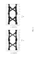
- FIG. 15 shows two plots presenting respectively the experimental data of a conventional microstrip sub-substrate used in conjunction with a microstrip circuit board (B) and of a GCPW sub-substrate of the present invention used in conjunction with a GCPW circuit board (A) when the feed signals have a bit rate of 35 Gbps; and
- FIG. 16 shows two plots presenting respectively the experimental data of a conventional microstrip sub-substrate used in conjunction with a microstrip circuit board (B) and of a GCPW sub-substrate of the present invention used in conjunction with a GCPW circuit board (A) when the feed signals have a bit rate of 40 Gbps.
- the present invention provides a driving circuit configured for two-end driving and for use with an optical communication module to carry out high-frequency signal transmission.
- the sub-substrate carrying the semiconductor chip has signal transmission wires formed as a grounded coplanar waveguide (GCPW) to reduce the parasitic effect associated with high-frequency transmission, thereby preventing discontinuous impedance matching and the generation of noise.
- GCPW grounded coplanar waveguide
- the flexible printed circuit (FPC) or printed circuit board (PCB) used in combination with the sub-substrate is also provided with GCPW signal transmission wires, and test results have shown that better signal connection can be achieved when both the FPC (or PCB) and the sub-substrate use GCPW signal transmission wires.
- FIG. 1 , FIG. 2 , and FIG. 3 show the first embodiment of the present invention in perspective view, in top view, and in sectional view respectively.
- the high-frequency transmission structure 100 in this embodiment essentially includes a main substrate 10 , a sub-substrate 20 provided on the main substrate 10 , and a circuit board 30 provided on the main substrate 10 and electrically connected to the sub-substrate 20 .
- the main substrate 10 may be a PCB, a ceramic board, or a plate or housing configured solely for supporting the sub-substrate 20 and the circuit board 30 .
- the present invention has no limitation in this regard.
- the sub-substrate 20 provided on the main substrate 10 is preferably fixed to the main substrate 10 by a thermally conductive adhesive, an electrically conductive adhesive, or a silver paste, or by welding an AuSn-based material.
- the present invention imposes no limitation in this regard, either.
- the sub-substrate 20 has a sub-substrate body 21 .
- the upper side of the sub-substrate body 21 is provided with a first signal pad area 211 and a second signal pad area 212 .
- the first signal pad area 211 and the second signal pad area 212 are symmetric with respect to each other.
- Each of the first signal pad area 211 and the second signal pad area 212 extends from one of two lateral portions of the sub-substrate body 21 in an extending direction toward the center of the sub-substrate body 21 and terminates in an end.
- the aforesaid end of the first signal pad area 211 is adjacent to, but spaced by a distance 213 from, the aforesaid end of the second signal pad area 212 .
- the first signal pad area 211 is configured for supporting a semiconductor chip 22 that is provided on the first signal pad area 211 .
- the second signal pad area 212 is provided with a jumper wire 23 connected to an electrode on the upper side of the semiconductor chip 22 .
- An electrode on the lower side of the semiconductor chip 22 is electrically connected to the underlying first signal pad area 211 .
- the semiconductor chip 22 is to be driven by the differential signals between the first signal pad area 211 and the second signal pad area 212 .
- the term “symmetric” refers to the two lateral metal pad areas (i.e., the first signal pad area 211 and the second signal pad area 212 ) being laid out and shaped in an identical manner. These pad areas, however, are not necessarily so laid out or shaped. More specifically, the first signal pad area 211 and the second signal pad area 212 need not have the same layout or shape, provided that they meet the symmetry requirement for impedance matching.
- the jumper wire 23 is preferably a gold wire ribbon for increased signal continuity.
- the semiconductor chip 22 is provided on the second signal pad area 212 instead, and the jumper wire 23 is provided on the first signal pad area 211 and is connected to the electrode on the upper side of the semiconductor chip 22 .
- This alternative arrangement is equivalent to that described above and shown in the drawings.
- the first signal pad area 211 and the second signal pad area 212 employ the principle of a GCPW to increase the stability, and hence improve the transmission, of high-frequency signals.
- a first grounding pad area 214 and a first grounding pad area 215 which constitute part a coplanar waveguide, are provided on two lateral sides of the first signal pad area 211 and the second signal pad area 212 respectively.
- a first grounding layer 216 is provided on the bottom side of the sub-substrate body 21 .
- One or a plurality of via holes 217 are formed in each of the first grounding pad areas 214 and 215 and extend through the sub-substrate body 21 to electrically connect the first grounding pad areas 214 and 215 and the first grounding layer 216 .
- the first grounding layer 216 is provided as an inner layer of the sub-substrate body 21 instead; the present invention imposes no limitation in this regard.
- the first grounding layer 216 can also be replaced by a grounding layer 11 of the main substrate 10 ; the present invention imposes no limitation in this regard.
- the sub-substrate body 21 of the sub-substrate 20 is preferably a ceramic heat-dissipating substrate, such as alumina (Al 2 O 3 ), aluminum nitride (AlN), or a material doped with Al 2 O 3 or AlN.
- a ceramic heat-dissipating substrate such as alumina (Al 2 O 3 ), aluminum nitride (AlN), or a material doped with Al 2 O 3 or AlN.
- Al 2 O 3 aluminum nitride
- AlN aluminum nitride
- the body of the main substrate 10 may be provided with a heat guiding mechanism configured to work with the sub-substrate 20 ; the present invention has no limitation in this respect.
- a first metal pad area 31 and a second metal pad area 32 are provided on two lateral portions of the circuit board 30 respectively.
- a second grounding pad area 33 and a second grounding pad area 34 which constitute part of a coplanar waveguide, are provided on two lateral sides of each of the first metal pad area 31 and the second metal pad area 32 respectively.
- the first metal pad area 31 is connected to the first signal pad area 211 by an electrical connection means 311 .
- the second metal pad area 32 is connected to the second signal pad area 212 by an electrical connection means 321 .
- Each of the second grounding pad areas 33 is connected to the first grounding pad area 215 by an electrical connection means 331 .
- Each of the second grounding pad areas 34 is connected to the first grounding pad area 214 by an electrical connection means 341 .
- a second grounding layer 35 is provided as an inner layer, or on the bottom side, of the circuit board 30 .
- One or a plurality of via holes 36 are formed in each of the second grounding pad areas 33 and 34 and extend through the circuit board 30 to electrically connect the second grounding pad areas 33 and 34 and the second grounding layer 35 .
- each of the electrical connection means 311 , 321 , 331 , and 341 is a jumper wire connected to the corresponding pad areas at its two ends. To enhance signal continuity, the jumper wire is preferably a gold wire ribbon.
- the electrical connection means 311 , 321 , 331 , and 341 may be solder balls or other similar electrical joints instead of jumper wires each configured to connect the pad areas at its two ends.
- the present invention has no limitation on the form of the electrical connection means 311 , 321 , 331 , and 341 .
- the circuit board 30 may be a PCB, an FPC, or a ceramic circuit board made, for example, of AlN or Al 2 O 3 .
- the sub-substrate 20 in this embodiment feeds signals to the semiconductor chip 22 in a two-end driving manner.
- the front end of the circuit board 30 is provided with an electrostatic discharge (ESD) protection circuit B 1 and a differential driving circuit B 2 .
- Input signals are fed through the ESD protection circuit B 1 to the input ends of the differential driving circuit B 2 .
- the differential driving circuit B 2 converts the input differential signals into amplified differential signals and outputs the latter signals in order to feed the differential signals to the semiconductor chip 22 through the first signal pad area 211 and the second signal pad area 212 of the circuit board 20 respectively.
- the semiconductor chip 22 sends out a signal-carrying light beam, which is guided into an optical fiber (not shown) for optical communication.
- FIG. 5 and FIG. 6 each of which represents the perspective view and sectional view of the second embodiment of the present invention.
- the high-frequency transmission structure 200 in this embodiment has a sub-substrate 20 A provided on the main substrate 10 A and the sub-substrate 20 A comprises a sub-substrate body 21 A.
- the sub-substrate body 21 A has an upper side provided with a first signal pad area 211 A and a second signal pad area 212 A, the first signal pad area 211 A and the second signal pad area 212 A are symmetric with respect to each other, each of the first signal pad area 211 A and the second signal pad area 212 A extends from one of two lateral portions of the sub-substrate body 21 A in an extending direction toward a center of the sub-substrate body 21 A and terminates in an end, the end of the first signal pad area 211 A is adjacent to but spaced from the end of the second signal pad area 212 A, the first signal pad area 211 A is configured for supporting a semiconductor chip 22 provided thereon, the second signal pad area 212 A is provided with a jumper wire 23 connected to an electrode of
- This embodiment also employs the principle of a GCPW to increase the stability, and hence improve the transmission, of high-frequency signals.
- the main difference comparing to the aforementioned first embodiment is that the first grounding pad area 214 A and the second grounding pad area 215 A on the lateral side of the first signal pad area 211 A and the second signal pad area 212 A are not provided with via holes, and the first grounding layer 216 of the sub-substrate 20 A is connected to the second grounding layer 35 of the circuit board 30 through the grounding layer 11 A of the main substrate 10 A, such that the first grounding layer 216 of the sub-substrate 20 A shares the grounding line with the second grounding layer 35 of the circuit board 30 , which can also reduce the effects of damaging and distorting the signal.
- the first grounding layer 216 A can also be replaced by a grounding layer 11 A of the main substrate 10 A; the present invention imposes no limitation in this regard.
- the grounding layer 11 A in this embodiment can be, for example, line layout configured on the main substrate, metal foil configured on the main substrate, solder or plating configured on the main substrate, or the likes configured on the main substrate; the present invention imposes no limitation to the example of the grounding layer 11 A.
- FIG. 7 , FIG. 8 , and FIG. 9 each of which represents the perspective view, front view, and top view of the third embodiment of the present invention.
- the high-frequency transmission structure 300 in this embodiment has a base 40 and a sub-substrate 20 B.
- the base 40 comprises a body 41 , two electrode pins 42 extending through the body 41 , and an expanding pin 45 extending through the body 41 . There is an insulation layer 43 provided between the body 41 and each of the two electrode pins 42 respectively and the expanding pin 45 .
- the base 40 comprises a core column 44 configured vertically on the body 41 and one vertical side of the core column 44 is provided as a combining surface for one side of the sub-substrate 20 B to combine with.
- the sub-substrate 20 B can be vertically fixed on the body 41 by other positioning means, such as welding, adhering, plugging, or the likes; the present invention imposes no limitation.
- the sub-substrate 20 B has a sub-substrate body 21 B.
- the sub-substrate body 21 B has an upper side provided with a first signal pad area 211 B and a second signal pad area 212 B, the first signal pad area 211 B and the second signal pad area 212 B are symmetric with respect to each other, each of the first signal pad area 211 B and the second signal pad area 212 B extends from one of two lateral portions of the sub-substrate body 21 B in an extending direction toward a center of the sub-substrate body 21 B and terminates in an end, the end of the first signal pad area 211 B is adjacent to but spaced from the end of the second signal pad area 212 B, the first signal pad area 211 B is configured for supporting a semiconductor chip 22 provided thereon, the second signal pad area 212 B is provided with a jumper wire 23 connected to an electrode of the semiconductor chip 22 , the electrode below the semiconductor chip 22 is connected to the first signal pad area 211 B by electrical connection, and
- this embodiment employs the principle of a GCPW to increase the stability.
- the sub-substrate 20 B is vertically configured on the body 41 , one vertical side of the sub-substrate body 21 B is configured with a first signal pad area 211 B and a second signal pad area 212 B, and the first signal pad area 211 B and the second signal pad area 212 B are connected to the two electrode pins 42 by electrical connection respectively.
- the first signal pad area 211 B and the second signal pad area 212 B can be electrically connected to the two electrode pins 42 by welding or the likes, such as the jump wire, the present invention has no limitation.
- the other vertical side of the sub-substrate body 21 B or the inner layer of the sub-substrate body 21 B is configured with a grounding layer 216 B.
- the grounding pad areas 214 B or 215 B is formed with at least one via hole 217 B extending through the sub-substrate body 21 B in order for the via holes 217 B to electrically connect the grounding pad area 214 B or 215 B and the grounding layer 216 B.
- FIG. 10 In another preferred embodiment, referring to FIG.
- the sub-substrate 20 B comprises a gold-plated side layer 218 B configured on the side edge of sub-substrate body 21 B, wherein the two lateral sides of the gold-plated side layer 218 B are connected respectively to the grounding pad areas 214 B or 215 B and the grounding layer 216 B by an electrical connection.
- the grounding pad areas 214 B or 215 B and the grounding layer 216 B can be connected to base 41 by the gold-plated side layer 218 B for grounding such that the parasitic capacitance can be inhibited.
- the sub-substrate 20 B instead of being configured on the grounding layer 216 B, can use the core column 44 to replace the grounding layer 216 B for grounding, and the grounding pad areas 214 B or 215 B can be connected with the body 41 (such as the aforementioned gold-plated side layer 218 B and welding) or one vertical side of the core column 44 (such as the aforementioned via holes 217 B) by electrical connection for obtaining the same effect of inhibiting parasitic capacitance.
- FIG. 12 to FIG. 16 each of which discloses a plot or plots based on the experiment results of a conventional microstrip sub-substrate used in conjunction with a microstrip circuit board (B) and of a GCPW sub-substrate of the present invention used in conjunction with a GCPW circuit board (A).
- the experimental group is a sub-substrate 20 of the present invention, which has a GCPW circuit and is used in conjunction with a circuit board 30 with a GCPW circuit
- the control group is a conventional microstrip sub-substrate used in conjunction with a microstrip circuit board.
- the experimental data of the experimental groups are indicated as A in the drawings, and those of the control groups, as B.
- signals are fed through the first metal pad area 31 and the second metal pad area 32 of the circuit board 30 in order to obtain detection signals from the first signal pad area 211 and the jumper wire 23 , which serve as the output ends.
- signals are fed through signal wires of the microstrip circuit board in order to obtain detection signals from the output ends (i.e., signal wires) of the microstrip sub-substrate.
- the solid line represents the experimental group A
- the dotted line represents the control group B
- the vertical axis represents reflection loss (unit: dB)
- the horizontal axis represents frequency (unit: GHz).
- the power level (in the unit of dB) of the reflection loss of the experimental group A is significantly lower than that of the control group B when the input signals are high-frequency (higher than 20 GHz) signals.
- the solid line represents the experimental group A
- the dotted line represents the control group B
- the vertical axis represents insertion loss (unit: dB)
- the horizontal axis represents frequency (unit: GHz).
- the power level (in the unit of dB) of the insertion loss of the experimental group A is much higher than that of the control group B when the input signals are high-frequency (higher than 20 GHz) signals. This means that insertion loss is significantly reduced in the experimental group A, as compared with that in the control group B.
- the plot on the left shows the experimental data of the experimental group A
- the plot on the right shows the experimental data of the control group B.
- the vertical axis in each plot represents signal amplitude (unit: Voltage) while the horizontal axis represents time (unit: second).
- the feed signals have a bit rate of 25 Gbps
- the amplitudes of the output signals of the experimental group A remain at reasonable values.
- a slight structural insertion loss has rendered the waveforms of the output signals of the control group B relatively unstable, although the difference between signals is identifiable.
- the plot on the left shows the experimental data of the experimental group A
- the plot on the right shows the experimental data of the control group B.
- the vertical axis in each plot represents signal amplitude (unit: Voltage) while the horizontal axis represents time (unit: second).
- the feed signals have a bit rate of 35 Gbps
- the amplitudes of the output signals of the experimental group A still stay at reasonable values, but a great structural insertion loss has rendered the waveforms of the output signals of the control group B even more unstable, with the amplitude of noise approaching 0.5 V.
- the signal-to-noise ratio of the control group B is much lower than that of the experimental group A.
- the plot on the left shows the experimental data of the experimental group A
- the plot on the right shows the experimental data of the control group B.
- the vertical axis in each plot represents signal amplitude (unit: Voltage) while the horizontal axis represents time (unit: second).
- the feed signals have a bit rate of 40 Gbps
- the amplitudes of the output signals of the experimental group A remain at reasonable values, but the waveforms of the output signals of the control group B are now indistinguishable, with the amplitude of noise approaching 0.6 V. Consequently, the control group B has a very low signal-to-noise ratio.
- the GCPW sub-substrates and GCPW circuit boards of the present invention can suppress noise and reduce insertion loss as well as reflection loss much more effectively than the control groups when fed with high-frequency signals.
- the present invention has the following advantages comparing to the prior art: Firstly, the present invention has excellent high-frequency transmission properties and is less prone to signal loss and signal distortion than the prior art. Secondly, thanks to the two-end driving technique, the present invention can reduce reflection in signal transmission and dispense with resistors otherwise required to achieve impedance matching. Lastly, the present invention features exceptionally effective heat dissipation to prevent excessive heat from accumulating in, and having an adverse effect on the operation of, the semiconductor device.
Landscapes
- Semiconductor Lasers (AREA)
- Chemical & Material Sciences (AREA)
- Engineering & Computer Science (AREA)
- Ceramic Engineering (AREA)
- Physics & Mathematics (AREA)
- Geometry (AREA)
- Optical Modulation, Optical Deflection, Nonlinear Optics, Optical Demodulation, Optical Logic Elements (AREA)
- Waveguides (AREA)
Abstract
Description
Claims (20)
Applications Claiming Priority (3)
| Application Number | Priority Date | Filing Date | Title |
|---|---|---|---|
| TW105215535 | 2016-10-13 | ||
| TW105217484U TWM538242U (en) | 2016-10-13 | 2016-11-16 | Double-end driven high frequency sub-substrate structure and high-frequency transmission structure containing same |
| TW105217484U | 2016-11-16 |
Publications (1)
| Publication Number | Publication Date |
|---|---|
| US9847307B1 true US9847307B1 (en) | 2017-12-19 |
Family
ID=58774875
Family Applications (1)
| Application Number | Title | Priority Date | Filing Date |
|---|---|---|---|
| US15/459,523 Expired - Fee Related US9847307B1 (en) | 2016-10-13 | 2017-03-15 | Two-end driving, high-frequency sub-substrate structure and high-frequency transmission structure including the same |
Country Status (3)
| Country | Link |
|---|---|
| US (1) | US9847307B1 (en) |
| CN (1) | CN206259350U (en) |
| TW (1) | TWM538242U (en) |
Families Citing this family (1)
| Publication number | Priority date | Publication date | Assignee | Title |
|---|---|---|---|---|
| CN119805684A (en) * | 2019-05-09 | 2025-04-11 | 苏州旭创科技有限公司 | Optical component and optical module having the same |
Citations (4)
| Publication number | Priority date | Publication date | Assignee | Title |
|---|---|---|---|---|
| US7405477B1 (en) * | 2005-12-01 | 2008-07-29 | Altera Corporation | Ball grid array package-to-board interconnect co-design apparatus |
| US9117835B2 (en) * | 2009-08-31 | 2015-08-25 | Stalix Llc | Highly integrated miniature radio frequency module |
| US20160379944A1 (en) * | 2012-06-14 | 2016-12-29 | Skyworks Solutions, Inc. | Power amplifier modules with power amplifier and transmission line and related systems, devices, and methods |
| US20170162525A1 (en) * | 2015-12-03 | 2017-06-08 | Kabushiki Kaisha Toshiba | High frequency semiconductor amplifier |
-
2016
- 2016-11-16 TW TW105217484U patent/TWM538242U/en not_active IP Right Cessation
- 2016-12-08 CN CN201621340196.XU patent/CN206259350U/en not_active Expired - Fee Related
-
2017
- 2017-03-15 US US15/459,523 patent/US9847307B1/en not_active Expired - Fee Related
Patent Citations (4)
| Publication number | Priority date | Publication date | Assignee | Title |
|---|---|---|---|---|
| US7405477B1 (en) * | 2005-12-01 | 2008-07-29 | Altera Corporation | Ball grid array package-to-board interconnect co-design apparatus |
| US9117835B2 (en) * | 2009-08-31 | 2015-08-25 | Stalix Llc | Highly integrated miniature radio frequency module |
| US20160379944A1 (en) * | 2012-06-14 | 2016-12-29 | Skyworks Solutions, Inc. | Power amplifier modules with power amplifier and transmission line and related systems, devices, and methods |
| US20170162525A1 (en) * | 2015-12-03 | 2017-06-08 | Kabushiki Kaisha Toshiba | High frequency semiconductor amplifier |
Also Published As
| Publication number | Publication date |
|---|---|
| TWM538242U (en) | 2017-03-11 |
| CN206259350U (en) | 2017-06-16 |
Similar Documents
| Publication | Publication Date | Title |
|---|---|---|
| US10251258B2 (en) | Dielectric waveguide core between ground planes secured in a channel | |
| US8643168B1 (en) | Integrated circuit package with input capacitance compensation | |
| US9006910B2 (en) | Interconnection structure | |
| JP5881752B2 (en) | Transistor outline housing and manufacturing method thereof | |
| US8119931B1 (en) | Differential vertical structure for high density, low layer count packages | |
| US20130265733A1 (en) | Interchip communication using an embedded dielectric waveguide | |
| US20130101251A1 (en) | Optical Module and Multilayer Substrate | |
| US20130265734A1 (en) | Interchip communication using embedded dielectric and metal waveguides | |
| US10042133B2 (en) | Optical module | |
| WO2014097580A1 (en) | Electronic circuit board and connector connection structure | |
| KR20040084780A (en) | Method and apparatus for intra-layer transitions and connector launch in multilayer circuit boards | |
| CN104996001B (en) | Electrical connection interface for connecting the electrical lead for being used for high speed data transfer | |
| CN102263588B (en) | Optical communications device having a mounting core and method | |
| KR100586278B1 (en) | Printed Circuit Boards for High Speed Semiconductor Packages with Bonded Wire Shield Structures | |
| CN111223827B (en) | Transition circuits for integrated circuit chips | |
| JP2017199905A (en) | Optical semiconductor device | |
| JP2009004460A (en) | Optical communication module and forming method of wiring pattern | |
| US11937368B2 (en) | Structure for circuit interconnects | |
| US9847307B1 (en) | Two-end driving, high-frequency sub-substrate structure and high-frequency transmission structure including the same | |
| CN110637399B (en) | Optical module and method for manufacturing the same | |
| US7471174B2 (en) | Connection structure for coaxial connector and multilayer substrate | |
| JP2004335584A (en) | Semiconductor package | |
| CN105977241A (en) | Packaging structure for photoelectron integrated chip | |
| US11398866B2 (en) | Optical semiconductor device, optical transmission module, and optical transceiver | |
| US11540383B2 (en) | Signal transmission circuit and printed circuit board |
Legal Events
| Date | Code | Title | Description |
|---|---|---|---|
| AS | Assignment |
Owner name: LUXNET CORPORATION, TAIWAN Free format text: ASSIGNMENT OF ASSIGNORS INTEREST;ASSIGNORS:CHEN, HO-I;HUANG, PO-CHAO;CHIU, YI-CHING;AND OTHERS;REEL/FRAME:041658/0350 Effective date: 20161219 |
|
| STCF | Information on status: patent grant |
Free format text: PATENTED CASE |
|
| FEPP | Fee payment procedure |
Free format text: ENTITY STATUS SET TO UNDISCOUNTED (ORIGINAL EVENT CODE: BIG.); ENTITY STATUS OF PATENT OWNER: LARGE ENTITY |
|
| MAFP | Maintenance fee payment |
Free format text: PAYMENT OF MAINTENANCE FEE, 4TH YEAR, LARGE ENTITY (ORIGINAL EVENT CODE: M1551); ENTITY STATUS OF PATENT OWNER: LARGE ENTITY Year of fee payment: 4 |
|
| FEPP | Fee payment procedure |
Free format text: MAINTENANCE FEE REMINDER MAILED (ORIGINAL EVENT CODE: REM.); ENTITY STATUS OF PATENT OWNER: LARGE ENTITY |
|
| LAPS | Lapse for failure to pay maintenance fees |
Free format text: PATENT EXPIRED FOR FAILURE TO PAY MAINTENANCE FEES (ORIGINAL EVENT CODE: EXP.); ENTITY STATUS OF PATENT OWNER: LARGE ENTITY |
|
| STCH | Information on status: patent discontinuation |
Free format text: PATENT EXPIRED DUE TO NONPAYMENT OF MAINTENANCE FEES UNDER 37 CFR 1.362 |
|
| FP | Lapsed due to failure to pay maintenance fee |
Effective date: 20251219 |