US9846945B2 - Method for generating orientation image - Google Patents
Method for generating orientation image Download PDFInfo
- Publication number
- US9846945B2 US9846945B2 US14/469,594 US201414469594A US9846945B2 US 9846945 B2 US9846945 B2 US 9846945B2 US 201414469594 A US201414469594 A US 201414469594A US 9846945 B2 US9846945 B2 US 9846945B2
- Authority
- US
- United States
- Prior art keywords
- current
- ratio
- component
- gradient
- lookup table
- Prior art date
- Legal status (The legal status is an assumption and is not a legal conclusion. Google has not performed a legal analysis and makes no representation as to the accuracy of the status listed.)
- Active, expires
Links
Images


Classifications
-
- G06T7/0085—
-
- G06K9/32—
-
- G—PHYSICS
- G06—COMPUTING; CALCULATING OR COUNTING
- G06T—IMAGE DATA PROCESSING OR GENERATION, IN GENERAL
- G06T7/00—Image analysis
- G06T7/10—Segmentation; Edge detection
- G06T7/13—Edge detection
Definitions
- the present invention generally relates to an image processing technique, in particular, to a method for generating an orientation image.
- Edge detection is a critical pre-processing step of object detection in the field of computer vision and image processing.
- the term “edge” is referred to as a set of neighboring pixels with sharp variation in an image, i.e. regions with discontinuous and rough neighboring pixels.
- a gradient intensity and a gradient orientation of each pixel may be accordingly calculated.
- image feature extraction may be performed in a follow-up process through, for example, a histogram of oriented gradient (HoG) technique so as to detect an object in the image.
- HoG histogram of oriented gradient
- Gy Gx ranges between ⁇ and + ⁇ , an arctangent lookup table may not provide enough coverage for all inputs. Additionally, to obtain the gradient orientation via a two-dimensional arctangent lookup table approach such that the lookup table is constructed based on positive and negative signs of horizontal gradients Gx and vertical gradients Gy as well as
- Gy Gx large memory space is required for storing such two-dimensional lookup table.
- the two-dimensional lookup table may be unfavorable to be loaded into an on-chip memory for real-time computation.
- the invention is directed to a method for generating an orientation image, where an orientation image associated with an input image may be generated precisely in real time with low-cost implementation.
- the invention is directed to a method for generating an orientation image, adapted to an electronic device, where the orientation image includes a plurality of image orientation angles, and each of the image orientation angles ranges between 0 and 2 ⁇ or between 0 and 360°.
- the method includes the following steps. First, a plurality of input pixels of an input image are received, where the input pixels include a current input pixel. Edge detection is performed on the current input pixel in a first direction and a second direction so as to respectively generate a first current gradient and a second current gradient with respect to the first direction and the second direction.
- a ratio of the first current gradient to a current gradient absolute sum is calculated so as to obtain a current ratio, where the current gradient absolute sum is a sum of an absolute value of the first current gradient and an absolute value of the second current gradient.
- a sign of the second current gradient is extracted so as to obtain a current sign.
- the current ratio and the current sign are input to a lookup table so as to obtain the image orientation angle corresponding to the current input pixel.
- the method for constructing the lookup table includes the following steps.
- a plurality of first components having positive signs, negative signs, and zeros as well as a plurality of second components having positive signs, negative signs, and zeros are provided.
- a first ratio corresponding to the first component is calculated, where the first ratio is equal to the first component divided by a square root of a sum of squares of the first component and the second component;
- a sign of the second component is extracted so as to obtain a reference sign;
- an orientation angle is calculated by using an arccosine function or an arcsine function according to the first ratio and the reference sign, where the orientation angle ranges between 0 and 2 ⁇ or between 0 and 360°;
- a second ratio corresponding to the first component is calculated, where the second ratio is equal to the first component divided by a sum of an absolute value of the first component and an absolute value of the second component; and the lookup table is constructed according to the second ratio, the reference sign
- the first direction is orthogonal to the second direction.
- the invention is directed to a method for generating an orientation image, adapted to an electronic device, where the orientation image includes a plurality of image orientation angles, and each of the image orientation angles ranges between 0 and ⁇ or between 0 and 180°.
- the method includes the following steps. First, a plurality of input pixels of an input image are received, where the input pixels include a current input pixel. Edge detection is performed on the current input pixel in a first direction and a second direction so as to respectively generate a first current gradient and a second current gradient with respect to the first direction and the second direction.
- a ratio of the first current gradient to a current gradient absolute sum is calculated so as to obtain a current ratio, where the current gradient absolute sum is a sum of an absolute value of the first current gradient and an absolute value of the second current gradient.
- the current ratio is input to a lookup table so as to obtain the image orientation angle corresponding to the current input pixel.
- the method for constructing the lookup table includes the following steps.
- a plurality of first components having positive signs, negative signs, and zeros as well as a plurality of second components having positive signs, negative signs, and zeros are provided.
- a first ratio corresponding to the first component is calculated, where the first ratio is equal to the first component divided by a square root of a sum of squares of the first component and the second component;
- an orientation angle is calculated by using an arccosine function or an arcsine function according to the first ratio and the reference sign, where the orientation angle ranges between 0 and ⁇ or between 0 and 180°;
- a second ratio corresponding to the first component is calculated, where the second ratio is equal to the first component divided by a sum of an absolute value of the first component and an absolute value of the second component;
- the lookup table is constructed according to the second ratio and the orientation angle, where an input of the lookup table is the second ratio, and where an output
- the first direction is orthogonal to the second direction.
- the present invention is directed to a method for generating an orientation image, adapted to an electronic device, where the orientation image includes a plurality of image orientation angles, and each of the image orientation angles ranges between 0 and ⁇ /4 or between 0 and 90°.
- the method includes the following steps. First, a plurality of input pixels of an input image are received, where the input pixels include a current input pixel. Edge detection is performed on the current input pixel in a first direction and a second direction so as to respectively generate a first current gradient and a second current gradient with respect to the first direction and the second direction.
- a ratio of an absolute value of the first current gradient to a current gradient absolute sum is calculated so as to obtain a current ratio, where the current gradient absolute sum is a sum of an absolute value of the first current gradient and an absolute value of the second current gradient.
- the current ratio is input to a lookup table so as to obtain the image orientation angle corresponding to the current input pixel.
- the method for constructing the lookup table includes the following steps.
- a plurality of first components having positive signs and zeros as well as a plurality of second components having positive signs and zeros are provided.
- a first ratio corresponding to the first component is calculated, where the first ratio is equal to the first component divided by a square root of a sum of squares of the first component and the second component;
- an orientation angle is calculated by using an arccosine function or an arcsine function according to the first ratio and the reference sign, where the orientation angle ranges between 0 and ⁇ /4 or between 0 and 90°;
- a second ratio corresponding to the first component is calculated, where the second ratio is equal to the first component divided by a sum of an absolute value of the first component and an absolute value of the second component;
- the lookup table is constructed according to the second ratio and the orientation angle, where an input of the lookup table is the second ratio, and where an output of the lookup table is the
- the first direction is orthogonal to the second direction.
- a lookup table mathematically equivalent to an arcsine lookup table or an arccosine lookup table is prestored in an electronic device, where large memory space is not a requirement.
- FIG. 1 illustrates a flowchart of a method for constructing a lookup table of an orientation image according to an embodiment of the invention.
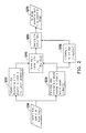
- FIG. 2 illustrates a flowchart of a method for generating an orientation image according to the embodiment of FIG. 1 .
- FIG. 3 illustrates a flowchart of another method for constructing a lookup table of an orientation image according to an embodiment of the invention.
- FIG. 4 illustrates a flowchart of a method for generating an orientation image according to the embodiment of FIG. 3 .
- FIG. 5 illustrates a flowchart of another method for constructing a lookup table of an orientation image according to an embodiment of the invention.
- FIG. 6 illustrates a flowchart of a method for generating an orientation image according to the embodiment of FIG. 5 .
- the main concept of the invention is to perform an absolute computation (
- FIG. 1 illustrates a flowchart of a method for constructing a lookup table of an orientation image according to an embodiment of the invention.
- the lookup table herein is mathematically equivalent to an arcsine lookup table or an arccosine lookup table and is adapted to generate an orientation image with orientation angles ranging between 0 and 2 ⁇ or between 0 and 360°.
- Step S 110 a plurality of first components with respect to a first direction and having positive signs, negative signs, and zeros as well as a plurality of second components with respect to a second direction and having positive signs, negative signs, and zeros are provided.
- the first direction is orthogonal to the second direction.
- each of the first components is a horizontal component Gx
- each of the second components is a vertical component Gy.
- the precision of the lookup table is determined by the number of the first components and the second components.
- Step S 120 a first ratio corresponding to the first component is calculated, where the first ratio is equal to the first component divided by a square root of a sum of squares of the first component and the second component and may be written as Eq. (1.1):
- Step S 140 an orientation angle is calculated by using an arccosine function or an arcsine function according to the first ratio and the reference sign respectively obtained in Step S 120 and Step S 130 .
- the orientation angle ⁇ may be obtained according to the reference sign S. Since the first component is set to the horizontal component Gx, the orientation angle ⁇ may be obtained by using the arcsine function arcsin(R 1 ) in conjunction with the orientation angle ⁇ .
- Step S 150 a second ratio corresponding to the first component is calculated, where the second ratio is equal to the first component divided by a sum of an absolute value of the first component and an absolute value of the second component and may be written as Eq. (1.3):
- R 2 Gx ( ⁇ Gx ⁇ + ⁇ Gy ⁇ ) Eq . ⁇ ( 1.3 ) where R 2 represents the second ratio.
- Step S 160 the lookup table is constructed according to the second ratio, the reference sign, and the orientation angle computed in Step S 140 , where inputs of the lookup table are the second ratio and the reference sign, and an output of the lookup table is the orientation angle. Since the function for calculating the first ratio R 1
- the lookup table constructed in Step S 160 is mathematically equivalent to the arcsine lookup table constructed based on the first ratio, the reference sign, and the orientation angle.
- FIG. 2 illustrates a flowchart of a method for generating an orientation image according to the embodiment of FIG. 1 .
- the orientation image in the present embodiment includes a plurality of image orientation angles, where each of the image orientation angles ranges between 0 and 2 ⁇ or between 0 and 360°.
- the method is adapted to an electronic device with an image processing feature such as a personal computer, a laptop computer, a digital camera, a digital camcorder, a web camera, a smart phone, a tabular computer, a vehicle event recorder, a vehicle video and audio system, and so forth.
- the lookup table constructed in the embodiment of FIG. 1 is prestored in the electronic device.
- Step S 210 a plurality of input pixels of an input image are received in Step S 210 , where the input pixels includes a current input pixel.
- the input pixels are arranged in a matrix with columns and rows. Since the processing step is the same for each of the input pixels, only the current input pixel among the input pixels would be illustrated hereinafter.
- Step S 220 and Step 230 edge detection is performed on the current input pixel in a first direction and a second direction so as to respectively generate a first current gradient and a second current gradient with respect to the first direction and the second direction.
- gradients of the current pixel with respect to different directions may be calculated by using an edge detection filter.
- the first direction is orthogonal to the second direction.
- the first current gradient with respect to the first direction and the second current gradient with respect to the second direction are a horizontal gradient Gx′ and a vertical gradient Gy′ of the current input pixel respectively.
- Step S 240 a ratio of the first current gradient to a current gradient absolute sum is calculated so as to obtain a current ratio, where the current gradient absolute sum is a sum of an absolute value of the first current gradient and an absolute value of the second current gradient, and the current ratio R′ may be written as Eq. (2.1):
- Step S 260 the current ratio and the current sign are input to the lookup table constructed in FIG. 1 so as to obtain the image orientation angle corresponding to the current input pixel, and the image orientation angle is output in Step S 270 . After all of the input pixels of the input image are processed, the orientation image ranging between 0 and 2 ⁇ or between 0 and 360° would then be generated.
- FIG. 3 illustrates a flowchart of another method for constructing a lookup table of an orientation image according to an embodiment of the invention.
- FIG. 4 illustrates a flowchart of a method for generating an orientation image according to the embodiment of FIG. 3 .
- the lookup table constructed in FIG. 3 is mathematically equivalent to an arcsine lookup table or an arccosine lookup table and is adapted to generate an orientation image with orientation angles ranging between 0 and ⁇ or between 0 and 180°.
- the steps illustrated in FIG. 3 and FIG. 4 are similar to those in FIG. 1 and FIG. 2 , and thus only the difference would be described in detail.
- Step S 310 a plurality of first components with respect to a first direction and having positive signs, negative signs, and zeros as well as a plurality of second components with respect to a second direction and having positive signs, negative signs, and zeros are provided.
- the first direction is orthogonal to the second direction.
- each of the first components is a horizontal component Gx
- each of the second components is a vertical component Gy.
- Step S 320 a first ratio corresponding to the first component is calculated, where the first ratio is equal to the first component divided by a square root of a sum of squares of the first component and the second component and may be written as Eq. (3.1):
- R 1 Gx Gx 2 + Gy 2 Eq . ⁇ ( 3.1 ) where R 1 represents the first ratio. Since the lookup table in the present embodiment is adapted to generate an orientation image with orientation angles ranging between 0 and ⁇ or between 0 and 180°, a sign of the second component (i.e. the vertical component) is not associated with the construction of the lookup table. A sign extraction process similar to Step S 130 would not be performed on the second component herein.
- Step S 330 a second ratio corresponding to the first component is calculated, where the second ratio is equal to the first component divided by a sum of an absolute value of the first component and an absolute value of the second component, and may be written as Eq. (3.2):
- R 2 Gx ( ⁇ Gx ⁇ + ⁇ Gy ⁇ ) Eq . ⁇ ( 3.2 ) where R 2 represents the second ratio.
- Step S 340 an orientation angle is calculated by using an arccosine function or an arcsine function according to the first ratio obtained in Step S 320 . Since the first ratio has a positive or negative sign, the orientation angle ⁇ calculated herein may range between 0 and ⁇ or between 0 and 180°.
- Step S 350 the lookup table is constructed according to the second ratio and the orientation angle computed in Step S 340 , where an input of the lookup table is the second ratio, and an output of the lookup table is the orientation angle.
- the lookup table constructed in Step S 350 is mathematically equivalent to the arcsine lookup table constructed based on the first ratio and the orientation angle.
- the orientation image in the present embodiment includes a plurality of image orientation angles, where each of the image orientation angles ranges between 0 and ⁇ or between 0 and 180°.
- the method in the present embodiment is adapted to an electronic device similar to that in the embodiment of FIG. 2 , and the lookup table constructed in the embodiment of FIG. 3 is prestored in the electronic device.
- Step S 410 a plurality of input pixels of an input image are received in Step S 410 , where the input pixels includes a current input pixel. Similarly, since the processing step is the same for each of the input pixels, only the current input pixel among the input pixels would be illustrated hereinafter.
- Step S 420 and Step S 430 edge detection is performed on the current input pixel in a first direction and a second direction so as to respectively generate a first current gradient and a second current gradient with respect to the first direction and the second direction.
- the first direction is orthogonal to the second direction.
- the first current gradient with respect to the first direction and the second current gradient with respect to the second direction are a horizontal gradient Gx′ and a vertical gradient Gy′ of the current input pixel respectively.
- Step S 440 a ratio of the first current gradient to a current gradient absolute sum is calculated so as to obtain a current ratio, where the current gradient absolute sum is a sum of an absolute value of the first current gradient and an absolute value of the second current gradient, and the current ratio R′ may be written as Eq. (4.1):
- Step S 450 the current ratio computed in Step S 440 is input to the lookup table constructed in FIG. 3 so as to obtain the image orientation angle corresponding to the current input pixel, and the image orientation angle is output in Step S 460 .
- the orientation image ranging between 0 and ⁇ or between 0 and 180° would then be generated.
- FIG. 5 illustrates a flowchart of another method for constructing a lookup table of an orientation image according to an embodiment of the invention.
- FIG. 6 illustrates a flowchart of a method for generating an orientation image according to the embodiment of FIG. 5 .
- the lookup table constructed in FIG. 5 is mathematically equivalent to an arcsine lookup table or an arccosine lookup table and is adapted to generate an orientation image with orientation angles ranging between 0 and ⁇ /4 or between 0 and 90°.
- the steps illustrated in FIG. 5 and FIG. 6 are similar to those in FIG. 1 and FIG. 2 , and thus only the difference would be described in detail.
- Step S 510 a plurality of first components with respect to a first direction and having positive signs and zeros as well as a plurality of second components with respect to a second direction and having positive signs and zeros are provided.
- the first direction is orthogonal to the second direction.
- each of the first components is a horizontal component Gx
- each of the second components is a vertical component Gy.
- Step S 520 a first ratio corresponding to the first component is calculated, where the first ratio is equal to the first component divided by a square root of a sum of squares of the first component and the second component and may be written as Eq. (5.1):
- R 1 ⁇ Gx ⁇ Gx 2 + Gy 2 Eq . ⁇ ( 5.1 )
- R 1 represents the first ratio. Since the lookup table in the present embodiment is adapted to generate an orientation image with orientation angles ranging between 0 and ⁇ /4 or between 0 and 90°, the first component and the second component are positive or zeros. A sign extraction process similar to Step S 130 would not be performed on the second component herein.
- a second ratio corresponding to the first component is calculated in Step S 530 , where the second ratio is equal to the first component divided by a sum of an absolute value of the first component and an absolute value of the second component and may be written as Eq. (5.2):
- R 2 ⁇ Gx ⁇ ( ⁇ Gx ⁇ + ⁇ Gy ⁇ ) Eq . ⁇ ( 5.2 ) where R 2 represents the second ratio.
- Step S 540 an orientation angle is calculated by using an arccosine function or an arcsine function according to the first ratio obtained in Step S 520 . Since the first ratio is positive or zero, the orientation angle ⁇ calculated herein may range between 0 and ⁇ /4 or between 0 and 90°.
- Step S 550 the lookup table is constructed according to the second ratio and the orientation angle computed in Step S 540 , where an input of the lookup table is the second ratio, and an output of the lookup table is the orientation angle.
- the lookup table constructed in Step S 550 is mathematically equivalent to the arcsine lookup table constructed based on the first ratio and the orientation angle.
- the orientation image in the present embodiment includes a plurality of image orientation angles, where each of the image orientation angles ranges between 0 and ⁇ /4 or between 0 and 90°.
- the method in the present embodiment is adapted to an electronic device similar to that in the embodiment of FIG. 2 , and the lookup table constructed in the embodiment of FIG. 5 is prestored in the electronic device.
- Step S 610 a plurality of input pixels of an input image are received, where the input pixels includes a current input pixel. Similarly, since the processing step is the same for each of the input pixels, only the current input pixel among the input pixels would be illustrated hereinafter.
- Step S 620 and Step S 630 edge detection is performed on the current input pixel in a first direction and a second direction so as to respectively generate a first current gradient and a second current gradient with respect to the first direction and the second direction.
- the first direction is orthogonal to the second direction.
- the first current gradient with respect to the first direction and the second current gradient with respect to the second direction are a horizontal gradient Gx′ and a vertical gradient Gy′ of the current input pixel respectively.
- Step S 640 a ratio of an absolute value of the first current gradient to a current gradient absolute sum is calculated so as to obtain a current ratio, where the current gradient absolute sum is a sum of an absolute value of the first current gradient and an absolute value of the second current gradient, and the current ratio R′ may be written as Eq. (6.1):
- Step S 650 the current ratio computed in Step S 640 is input to the lookup table constructed in FIG. 5 so as to obtain the image orientation angle corresponding to the current input pixel, and the image orientation angle is output in Step S 660 .
- the orientation image ranging between 0 and ⁇ /4 or between 0 and 90° would then be generated.
- a lookup table mathematically equivalent to an arcsine lookup table or an arccosine lookup table is prestored in an electronic device, where large memory space is not a requirement.
Abstract
Description
and yet a square-root computation is expensive for a low-cost chip. On the other hand, to obtain the gradient orientation via an arctangent lookup table approach, since the value of
ranges between −∞ and +∞, an arctangent lookup table may not provide enough coverage for all inputs. Additionally, to obtain the gradient orientation via a two-dimensional arctangent lookup table approach such that the lookup table is constructed based on positive and negative signs of horizontal gradients Gx and vertical gradients Gy as well as
large memory space is required for storing such two-dimensional lookup table. The two-dimensional lookup table may be unfavorable to be loaded into an on-chip memory for real-time computation.
and yet a square-root computation is relatively expensive for a low-cost chip. The main concept of the invention is to perform an absolute computation (|Gx|+|Gy|) with lower computational cost instead of a square-root and a square computation (√{square root over (Gx2+Gy2)}) with higher computational cost as well as to pre-construct a lookup table mathematically equivalent to an arcsine lookup table or an arccosine lookup table, and thus an orientation image of an input image may be obtained precisely in real-time.
where R1 represents the first ratio. Since the lookup table in the present embodiment is adapted to generate an orientation image with orientation angles ranging between 0 and 2π or between 0 and 360°, in Step S130, a sign of the second component is extracted so as to obtain a reference sign, where the reference sign S may be written as Eq. (1.2):
S=sign(Gy) Eq. (1.2)
where R2 represents the second ratio.
and the function for calculating the second ratio R2
are both injective functions, the lookup table constructed in Step S160 is mathematically equivalent to the arcsine lookup table constructed based on the first ratio, the reference sign, and the orientation angle.
In Step S250, a sign of the second current gradient is extracted so as to obtain a current sign, where the current sign S′ may be written as Eq. (2.2):
S′=sign(Gy′) Eq. (2.2)
Next, in Step S260, the current ratio and the current sign are input to the lookup table constructed in
where R1 represents the first ratio. Since the lookup table in the present embodiment is adapted to generate an orientation image with orientation angles ranging between 0 and π or between 0 and 180°, a sign of the second component (i.e. the vertical component) is not associated with the construction of the lookup table. A sign extraction process similar to Step S130 would not be performed on the second component herein.
where R2 represents the second ratio.
where R2 represents the second ratio.
Since the orientation angles of the orientation image to be generate in the present embodiment would range between 0 and π/4 or between 0 and 90°, the first current gradient is restricted to be positive.
Claims (9)
Applications Claiming Priority (3)
| Application Number | Priority Date | Filing Date | Title |
|---|---|---|---|
| TW103125530 | 2014-07-25 | ||
| TW103125530A | 2014-07-25 | ||
| TW103125530A TWI511088B (en) | 2014-07-25 | 2014-07-25 | Method for generating orientation image |
Publications (2)
| Publication Number | Publication Date |
|---|---|
| US20160026887A1 US20160026887A1 (en) | 2016-01-28 |
| US9846945B2 true US9846945B2 (en) | 2017-12-19 |
Family
ID=55166975
Family Applications (1)
| Application Number | Title | Priority Date | Filing Date |
|---|---|---|---|
| US14/469,594 Active 2036-04-17 US9846945B2 (en) | 2014-07-25 | 2014-08-27 | Method for generating orientation image |
Country Status (2)
| Country | Link |
|---|---|
| US (1) | US9846945B2 (en) |
| TW (1) | TWI511088B (en) |
Families Citing this family (1)
| Publication number | Priority date | Publication date | Assignee | Title |
|---|---|---|---|---|
| CN112085059B (en) * | 2020-08-06 | 2023-10-20 | 温州大学 | Breast cancer image feature selection method based on improved sine and cosine optimization algorithm |
Citations (18)
| Publication number | Priority date | Publication date | Assignee | Title |
|---|---|---|---|---|
| US20010024311A1 (en) * | 2000-01-06 | 2001-09-27 | Larkin Kieran Gerard | Demodulation and phase estimation of two-dimensional patterns |
| US20040190787A1 (en) * | 2002-12-27 | 2004-09-30 | Yoshihiro Nakami | Image noise reduction |
| US20050168657A1 (en) * | 2004-01-30 | 2005-08-04 | Darren Neuman | Method and system for interpolator direction selection during edge detection |
| US20060233460A1 (en) * | 2003-02-25 | 2006-10-19 | Sony Corporation | Image processing device, method, and program |
| US20080310731A1 (en) * | 2007-06-18 | 2008-12-18 | Zeitera, Llc | Methods and Apparatus for Providing a Scalable Identification of Digital Video Sequences |
| US20090238440A1 (en) * | 2008-03-24 | 2009-09-24 | Lev Faivishevsky | Method, system and computer program product for edge detection |
| CN101551576A (en) | 2008-03-31 | 2009-10-07 | Hoya株式会社 | Photographic apparatus |
| US20100054595A1 (en) * | 2008-08-26 | 2010-03-04 | Microsoft Corporation | Automatic Image Straightening |
| US20100125442A1 (en) * | 2008-11-20 | 2010-05-20 | Nec Electronics Corporation | Model parameter extracting apparatus and model parameter extracting program for semiconductor device model |
| US20100134688A1 (en) * | 2008-11-28 | 2010-06-03 | Sony Corporation | Image processing system |
| US20100293173A1 (en) * | 2009-05-13 | 2010-11-18 | Charles Chapin | System and method of searching based on orientation |
| US20110134136A1 (en) * | 2009-12-03 | 2011-06-09 | Larry Seiler | Computing Level of Detail for Anisotropic Filtering |
| CN102722469A (en) | 2012-05-28 | 2012-10-10 | 西安交通大学 | Elementary transcendental function operation method based on floating point arithmetic unit and coprocessor for method |
| US20140028842A1 (en) * | 2011-01-02 | 2014-01-30 | Agent Video Intelligence Ltd. | Calibration device and method for use in a surveillance system for event detection |
| US20150125092A1 (en) * | 2013-04-12 | 2015-05-07 | Qualcomm Incorporated | Near infrared guided image denoising |
| US20150146994A1 (en) * | 2013-11-28 | 2015-05-28 | Canon Kabushiki Kaisha | Method, system and apparatus for determining a depth value of a pixel |
| US20150206022A1 (en) * | 2014-01-22 | 2015-07-23 | Cognizant Technology Solutions India Pvt. Ltd. | System and method for classifying a skin infection |
| US20150213059A1 (en) * | 2014-01-29 | 2015-07-30 | Raytheon Company | Method for detecting and recognizing boats |
Family Cites Families (8)
| Publication number | Priority date | Publication date | Assignee | Title |
|---|---|---|---|---|
| US6771835B2 (en) * | 2000-06-12 | 2004-08-03 | Samsung Electronics Co., Ltd. | Two-dimensional non-linear interpolation system based on edge information and two-dimensional mixing interpolation system using the same |
| US7253738B2 (en) * | 2005-03-10 | 2007-08-07 | Delphi Technologies, Inc. | System and method of detecting eye closure based on edge lines |
| CN101873436B (en) * | 2009-04-27 | 2011-12-07 | 倚强科技股份有限公司 | Luminance compensation method using multiwire interpolated lens |
| CN102262785B (en) * | 2010-05-24 | 2014-01-29 | 珠海扬智电子有限公司 | Edge smooth method and scale method for bitmap font |
| GB2487242A (en) * | 2011-01-17 | 2012-07-18 | Sony Corp | Interpolation Using Shear Transform |
| TWI516119B (en) * | 2011-01-25 | 2016-01-01 | 華晶科技股份有限公司 | Electronic apparatus, image capturing apparatus and method thereof |
| TW201301199A (en) * | 2011-02-11 | 2013-01-01 | Vid Scale Inc | Edge-based video interpolation for video and image upsampling |
| TWI493502B (en) * | 2011-09-23 | 2015-07-21 | Altek Corp | Processing method for image rotating and apparatus thereof |
-
2014
- 2014-07-25 TW TW103125530A patent/TWI511088B/en active
- 2014-08-27 US US14/469,594 patent/US9846945B2/en active Active
Patent Citations (20)
| Publication number | Priority date | Publication date | Assignee | Title |
|---|---|---|---|---|
| US20010024311A1 (en) * | 2000-01-06 | 2001-09-27 | Larkin Kieran Gerard | Demodulation and phase estimation of two-dimensional patterns |
| US7043082B2 (en) * | 2000-01-06 | 2006-05-09 | Canon Kabushiki Kaisha | Demodulation and phase estimation of two-dimensional patterns |
| US20040190787A1 (en) * | 2002-12-27 | 2004-09-30 | Yoshihiro Nakami | Image noise reduction |
| US20060233460A1 (en) * | 2003-02-25 | 2006-10-19 | Sony Corporation | Image processing device, method, and program |
| US20050168657A1 (en) * | 2004-01-30 | 2005-08-04 | Darren Neuman | Method and system for interpolator direction selection during edge detection |
| US20080310731A1 (en) * | 2007-06-18 | 2008-12-18 | Zeitera, Llc | Methods and Apparatus for Providing a Scalable Identification of Digital Video Sequences |
| US20090238440A1 (en) * | 2008-03-24 | 2009-09-24 | Lev Faivishevsky | Method, system and computer program product for edge detection |
| CN101551576A (en) | 2008-03-31 | 2009-10-07 | Hoya株式会社 | Photographic apparatus |
| US20100054595A1 (en) * | 2008-08-26 | 2010-03-04 | Microsoft Corporation | Automatic Image Straightening |
| US20100125442A1 (en) * | 2008-11-20 | 2010-05-20 | Nec Electronics Corporation | Model parameter extracting apparatus and model parameter extracting program for semiconductor device model |
| US20100134688A1 (en) * | 2008-11-28 | 2010-06-03 | Sony Corporation | Image processing system |
| US20100293173A1 (en) * | 2009-05-13 | 2010-11-18 | Charles Chapin | System and method of searching based on orientation |
| US20110134136A1 (en) * | 2009-12-03 | 2011-06-09 | Larry Seiler | Computing Level of Detail for Anisotropic Filtering |
| TW201131513A (en) | 2009-12-03 | 2011-09-16 | Intel Corp | Computing level of detail for anisotropic filtering |
| US20140028842A1 (en) * | 2011-01-02 | 2014-01-30 | Agent Video Intelligence Ltd. | Calibration device and method for use in a surveillance system for event detection |
| CN102722469A (en) | 2012-05-28 | 2012-10-10 | 西安交通大学 | Elementary transcendental function operation method based on floating point arithmetic unit and coprocessor for method |
| US20150125092A1 (en) * | 2013-04-12 | 2015-05-07 | Qualcomm Incorporated | Near infrared guided image denoising |
| US20150146994A1 (en) * | 2013-11-28 | 2015-05-28 | Canon Kabushiki Kaisha | Method, system and apparatus for determining a depth value of a pixel |
| US20150206022A1 (en) * | 2014-01-22 | 2015-07-23 | Cognizant Technology Solutions India Pvt. Ltd. | System and method for classifying a skin infection |
| US20150213059A1 (en) * | 2014-01-29 | 2015-07-30 | Raytheon Company | Method for detecting and recognizing boats |
Also Published As
| Publication number | Publication date |
|---|---|
| TW201604836A (en) | 2016-02-01 |
| US20160026887A1 (en) | 2016-01-28 |
| TWI511088B (en) | 2015-12-01 |
Similar Documents
| Publication | Publication Date | Title |
|---|---|---|
| US9418319B2 (en) | Object detection using cascaded convolutional neural networks | |
| US20230081645A1 (en) | Detecting forged facial images using frequency domain information and local correlation | |
| US11568682B2 (en) | Recognition of activity in a video image sequence using depth information | |
| US10187546B2 (en) | Method and device for correcting document image captured by image pick-up device | |
| CN107301402B (en) | Method, device, medium and equipment for determining key frame of real scene | |
| US10740912B2 (en) | Detection of humans in images using depth information | |
| US20150206318A1 (en) | Method and apparatus for image enhancement and edge verificaton using at least one additional image | |
| US20150093040A1 (en) | Backlight Detection Method and Device | |
| WO2017214968A1 (en) | Method and apparatus for convolutional neural networks | |
| US9824267B2 (en) | Writing board detection and correction | |
| CN103914876A (en) | Method and apparatus for displaying video on 3D map | |
| US9196051B2 (en) | Electronic equipment with image analysis function and related method | |
| US20160123722A1 (en) | Computing device and method for analyzing thickness | |
| US8483487B2 (en) | Image processing device and method for capturing object outline | |
| US8126275B2 (en) | Interest point detection | |
| Żak et al. | Local image features matching for real-time seabed tracking applications | |
| US9846945B2 (en) | Method for generating orientation image | |
| CN111783777B (en) | Image processing method, apparatus, electronic device, and computer readable medium | |
| CN107146245B (en) | Image matching method and device | |
| CN115619791B (en) | Article display detection method, device, equipment and readable storage medium | |
| CN111192214A (en) | Image processing method and device, electronic equipment and storage medium | |
| US9392293B2 (en) | Accelerated image processing | |
| CN110619597A (en) | Semitransparent watermark removing method and device, electronic equipment and storage medium | |
| US20140348416A1 (en) | Stereo image rectification apparatus and method | |
| US20180061078A1 (en) | Image processing device, image processing method, and non-transitory computer-readable recording medium |
Legal Events
| Date | Code | Title | Description |
|---|---|---|---|
| AS | Assignment |
Owner name: ALTEK AUTOTRONICS CORPORATION, TAIWAN Free format text: ASSIGNMENT OF ASSIGNORS INTEREST;ASSIGNORS:LIAW, MING-JIUN;LIN, CHAO-YI;REEL/FRAME:033635/0613 Effective date: 20140818 |
|
| STCF | Information on status: patent grant |
Free format text: PATENTED CASE |
|
| AS | Assignment |
Owner name: ALTEK CORPORATION, TAIWAN Free format text: MERGER;ASSIGNOR:ALTEK AUTOTRONICS CORPORATION;REEL/FRAME:056392/0846 Effective date: 20170717 |
|
| FEPP | Fee payment procedure |
Free format text: ENTITY STATUS SET TO UNDISCOUNTED (ORIGINAL EVENT CODE: BIG.); ENTITY STATUS OF PATENT OWNER: LARGE ENTITY |
|
| MAFP | Maintenance fee payment |
Free format text: PAYMENT OF MAINTENANCE FEE, 4TH YEAR, LARGE ENTITY (ORIGINAL EVENT CODE: M1551); ENTITY STATUS OF PATENT OWNER: LARGE ENTITY Year of fee payment: 4 |
|
| FEPP | Fee payment procedure |
Free format text: PETITION RELATED TO MAINTENANCE FEES GRANTED (ORIGINAL EVENT CODE: PTGR); ENTITY STATUS OF PATENT OWNER: LARGE ENTITY |