US984635A - Water-purifying apparatus. - Google Patents
Water-purifying apparatus. Download PDFInfo
- Publication number
- US984635A US984635A US41426608A US1908414266A US984635A US 984635 A US984635 A US 984635A US 41426608 A US41426608 A US 41426608A US 1908414266 A US1908414266 A US 1908414266A US 984635 A US984635 A US 984635A
- Authority
- US
- United States
- Prior art keywords
- water
- tanks
- motor
- stirring
- stirring devices
- Prior art date
- Legal status (The legal status is an assumption and is not a legal conclusion. Google has not performed a legal analysis and makes no representation as to the accuracy of the status listed.)
- Expired - Lifetime
Links
- XLYOFNOQVPJJNP-UHFFFAOYSA-N water Substances O XLYOFNOQVPJJNP-UHFFFAOYSA-N 0.000 description 63
- 238000003756 stirring Methods 0.000 description 23
- 238000011282 treatment Methods 0.000 description 11
- 239000000126 substance Substances 0.000 description 9
- 235000008733 Citrus aurantifolia Nutrition 0.000 description 2
- 241000196324 Embryophyta Species 0.000 description 2
- 235000011941 Tilia x europaea Nutrition 0.000 description 2
- 239000003153 chemical reaction reagent Substances 0.000 description 2
- 238000007599 discharging Methods 0.000 description 2
- 239000004571 lime Substances 0.000 description 2
- CDBYLPFSWZWCQE-UHFFFAOYSA-L Sodium Carbonate Chemical compound [Na+].[Na+].[O-]C([O-])=O CDBYLPFSWZWCQE-UHFFFAOYSA-L 0.000 description 1
- 241000382509 Vania Species 0.000 description 1
- AYJRCSIUFZENHW-DEQYMQKBSA-L barium(2+);oxomethanediolate Chemical compound [Ba+2].[O-][14C]([O-])=O AYJRCSIUFZENHW-DEQYMQKBSA-L 0.000 description 1
- 229940000425 combination drug Drugs 0.000 description 1
- 238000010586 diagram Methods 0.000 description 1
- 230000004048 modification Effects 0.000 description 1
- 238000012986 modification Methods 0.000 description 1
- 238000005381 potential energy Methods 0.000 description 1
- 230000001105 regulatory effect Effects 0.000 description 1
- 238000005096 rolling process Methods 0.000 description 1
Images
Classifications
-
- B—PERFORMING OPERATIONS; TRANSPORTING
- B01—PHYSICAL OR CHEMICAL PROCESSES OR APPARATUS IN GENERAL
- B01D—SEPARATION
- B01D21/00—Separation of suspended solid particles from liquids by sedimentation
- B01D21/0018—Separation of suspended solid particles from liquids by sedimentation provided with a pump mounted in or on a settling tank
Definitions
- WITNESSES I v 5- INV ENTOR S %W M a, mi
- Our invention relates particularly to means for economically operating water purifying plants, having special reference to manipulating the devices for introducing chemicals and operating stirring devices for treating the water. Its primary object is to employ the power to be obtained from the suppl; or the head of water in the tanks, to run the feeding and stirring devices, thus doing away with outside sources of power.
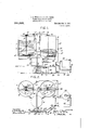
- Figure 1 is a diagram in elevation and partial section showing the essentials of a plant using our invention
- Fig. 2 is a plan of the same
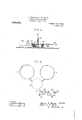
- Fig. 3 is a detail showing an alternative form of stirring device and means for operating the same
- Fig. 4 is a plan view illustrating a modification, in which a pump is used for drawing off the treated water.
- a water motor 11 which operates under the head of water in either tank, or the filter 9.
- shaft 12 may be provided with a pulley 13 which by a belt 14: operates a shaft 15, arranged to be engaged by clutches 15 and alternately or simultaneously revolve the pinions 16, 17, which in turn engage gears 18 on the shafts 19, 19,
- stirring paddles may be of theinclined form, .and fixed on the shaft 19* as shown in the right hand tank 6. j But in cases where violent stirring is necessary, as in using barium carbonate, we prefer to use the form of stirring device illustrated in detail in Fig. 3.
- the shaft 19 has radiating from it fixed arbors 20, on which are loosely.
- valved branchpipe 31 from the supply pip ei-2 6'or 28, leading through a displace- '-I nent;Ves sel32,- Where the water mixes and 'car'riesup with it a chemical reagent previousl'y' fed in from the chemical mixer 33,
- the stirring devices may be operated at any time by means of the water which is used in the system, the power due to the potential-energy of stored up water un-.
- our nvention may well be applied to thecontmuous water purifying system to use the power of outflowing water.
- stirring device in eachtank, a water motor connected in the outlet line from all said tanks, a Water inlet pipe having also a connection to said motor, and connections from the motor to the stirring devices whereby the latter may be continuously operated, the
- said motor being adapted to operate by the potential of the storedup water in the tanks to continue the operation of stirring de vices after the introduction of water has ceased.
- a treatment tank adapted for a holding an unobstructed body of water, of a water inlet discharging upwardly directly in the bottom, a motor in the line of the water inlet and operated thereby, and a stirring device in said tank actuated by said motor and comprising paddles located at the bottom of the tank under said body of water and means rotating them horizontally on a .vertlcal aXIS and snnultaneously revolvmg them on a horizontal pivot, whereby to agitate thesaid body of water both with a rolling motion, and with upward currents, substantially as described.
- Inwater purifying apparatus the combination with two alternately acting treatment tanks, of a water inlet and a water outlet both common to said tanks, a water motor in the common portion of the inlet and outlet adapted to be operated by either incoming or outgoing water, and stirring devices in the tanks operated by said motor.
Landscapes
- Chemical & Material Sciences (AREA)
- Chemical Kinetics & Catalysis (AREA)
- Mixers Of The Rotary Stirring Type (AREA)
Description
E. S. WOODS & J. G. W. GRETH. WAT-ER PURIFYING APPARATUS. APPLICATION FILED r2114; 190s.
9%,635. Patented Feb.21,1911.
2 SHEETS-SHEET 1. F I l3. 1..
SERVICE H- WITNESSES: 425 is INVENTORSI r 2?? WamM E. S. WOODS & J. G. W. GRETH.
WATER PURIPYING APPARATUS. APPLICATION IILED FEB. 4, 1908.
984,635. Patented Feb. 21, 1911.
2 SHEETS-SHEET 2.
WITNESSES: I v 5- INV ENTOR S %W M a, mi
sen-e35.
UNITED STATES orrion.
EDWIN S. WOODS, OF CHICAGO, ILLINOIS, AND JOHN C. W. GRETH, OF PITTSBURG, PENNSYLVANIA, ASSIGNORS T0 WM. B. SCAIFE & SONS COMPANY, OF PITTSBURG, PENNSYLVANIA. A CORPORATION OF NEW JERSEY.
WATER-PURIFYING APPARATUS.
Specification of Letters Patent.
Application filed February 4, 1908. Serial No. 414,266.
To all whom it may concern: Be it known that we, EDWIN S. Woonsand JOHN C. W. GRETH, citizens of the United States, residing, respectively, at Chicago, Illinois, and at Pittsburg, Pennsyl-, Vania, have jointly invented certain new and useful Improvements in Water-Purifying Apparatus, of which the following is a specification.
Our invention relates particularly to means for economically operating water purifying plants, having special reference to manipulating the devices for introducing chemicals and operating stirring devices for treating the water. Its primary object is to employ the power to be obtained from the suppl; or the head of water in the tanks, to run the feeding and stirring devices, thus doing away with outside sources of power.
Other objects and advantages of the invention will hereinafter appear.
In the accompanying drawings, illustrating the invention as applied to intermittent systems, Figure 1 is a diagram in elevation and partial section showing the essentials of a plant using our invention, and Fig. 2 is a plan of the same. Fig. 3 is a detail showing an alternative form of stirring device and means for operating the same. Fig. 4; is a plan view illustrating a modification, in which a pump is used for drawing off the treated water.
Frequently in water purifying systems, there is quite a considerable pressure at the service pipe, due to the head of water in the treatment or storage tanks or filter; and this power has generally been of no use, since the regulation of the outflow by valves merely wastes the pressure. Similarly the pressure of the feed pipe has been unused, and in most cases extra pumps have been used for service, where there is any elevation of the water necessary. There are generally stirring devices employed in such lants for mixing in the chemicals and aiding in the reaction and these stirring devices have heretofore been operated by special motors or outside power. Even if the power of incoming water be used, in intermittent sys tems the inflow ceases before the stirring devices are through their work and outside power was necessary. We propose herein a completely self contained plan-h"; needing no outside power.
Patented Feb. 21,1911. i
trate our invention, there are twin tanksti i and 7, as shown in Fig. 1, in which water is treated to the chemical and settled and drawn olf through floating outlet pipes8 to the filter 9, from whence it ordinarily flows heater or a boiler, or a storage tank such as used alongthe tracks of railways. Somewhere in the course of the outlet, as in the pipe 10, we place a water motor 11, which operates under the head of water in either tank, or the filter 9. Its shaft 12 may be provided with a pulley 13 which by a belt 14: operates a shaft 15, arranged to be engaged by clutches 15 and alternately or simultaneously revolve the pinions 16, 17, which in turn engage gears 18 on the shafts 19, 19,
for operating the s tirring paddles These stirring paddles may be of theinclined form, .and fixed on the shaft 19* as shown in the right hand tank 6. j But in cases where violent stirring is necessary, as in using barium carbonate, we prefer to use the form of stirring device illustrated in detail in Fig. 3. The shaft 19 has radiating from it fixed arbors 20, on which are loosely.
mounted pinions 21, having extensions 22, upon which the paddles 23 are carried. As the shaft 19 and arbors 20 revolve, the pinions and paddles are rotated by engagement through the pipe 10 to the service,'as for a K with a fixed rack 24 on'the bottom of the 7 tank.
By the above described means, whenever there is. water being used from either fine of the tanks 6.'and 7. which flows out through the filter, or when the filter 9 itself contains water and is properly elevated, there is available power to operate the s'tin ring devices, and this is so even though 'no water is being taken into the system. While water is being taken in. however, we may use this power, thus: The supply of water from pipe 25 in Fig. 1. is admittedto the treatment tanks not directly but through valve 25 motor 11, the pipe 26, and pipes 29 and .27, thus operating the water motor by pressure of the incoming water. In this Way the stirrlng device may always be operated by the use of either the water being fed into or taken out of the system.
Often it is sufficient to run thc'paddles in one tank while water is being taken from the other; and in this case we operate by admitting the water through pipes and '28 directly to pipe 29 and preferably admit it into the tanks at the bottom directly under the stirring devices as shown intank 6. The manipulation of the vvalves necessary in any case, will be plain from the drawing. V
In additionto the above described apparatus,and in order to provide a completely self contained system, requ1r1ng no power except the water pressure for. any purpose,
we may add the apparatus shown at the right of Fig. 1, which is essentially the same as that described in Greths application No.
388,139 filed August 12th, 1907, without the lime saturater therein. Briefly, it comprises a valved branchpipe 31 from the supply pip ei-2 6'or 28, leading through a displace- '-I nent;Ves sel32,- Where the water mixes and 'car'riesup with it a chemical reagent previousl'y' fed in from the chemical mixer 33,
as will be understood. Then this is used for the lime, the valve 31. being open and 34,
- 36 and 3S shut, the solutiouis fed through pipe to pipes 29 and 27 to the tanks. By regulating the valves 31 and 36 any desired proportion of feed water is diverted through the feeder 32. This apparatus has also extra branches 37 which, when valves 27 are closed and valves 38 are open, allows the reagent such as soda to be fed from the vessel 32 into the top of the treatment tanks in alternation or together, when desired. Either chemical may be fed in along-with the main volume of water, or in the case of some treatments, the entire charge of chemical in vessel 82'may be displaced and carried up at once without introducing any appr ciable amount of raw water with it. Where it is necessary to use a pump in drawing of]? the water for service, we arrange this part of the apparatus as in Fig. 4, where 40 is a pump in the pipe 10 leading from filter 9 and discharging through outlet pipe 41 after passing through the water motor 11. However, when desired the water motor can in all cases be cut out by means of a bypass 42 or 42, leading directly to the service pipe 41.
By the above described apparatus it will be evident that the stirring devices may be operated at any time by means of the water which is used in the system, the power due to the potential-energy of stored up water un-.
head in the treating tank, and-thereby operate the stirrmg devices. For example our nvention may well be applied to thecontmuous water purifying system to use the power of outflowing water.
Having thus described our [invention and illustrated its use, what .we claim as new and desire to secure by LettersPatent, is the following:
.1. The combination in a water purifying system, of a plurality of treatment tanks, a.
stirring device in eachtank, a water motor connected in the outlet line from all said tanks, a Water inlet pipe having also a connection to said motor, and connections from the motor to the stirring devices whereby the latter may be continuously operated, the
motor being driven either by incoming or outflowing water.
2. In water purifying apparatus, the com- .bination with a pair of treatment tanks,
of water in the treatmenttanks, substan-'v tially as described.
3. he water purlfying system, the com bination with treatment tanks and stirring devices therein, of means operated by the outflowing water to run the stirring devices, a chemical supply, and means actuated by the incoming water to feed the chemical supply into the system, substantially as described.
4. The combination in a water purifying system, of stirring devices, a chemical feeder, means operated by the incoming water to operate the feeder and means operated by either the incoming 'or outfiowing water to operate the stirring devices. I
5. The combination with a pluralityof water treatment tanks and means to fill and empty them in alternation, of stirring devices therein andmeans employing the potential of the stored up water to continue the operation of the stirring devices after the introduction of water has ceased.
6. The combination with a plurality of water treatment tanks and means to fill and empty them inalternation, of stirring devices in the tanks and a motor operated by the water flowing eitherto or from the tanks and actuating said stirrlng Cl6V1C8S,'
said motor being adapted to operate by the potential of the storedup water in the tanks to continue the operation of stirring de vices after the introduction of water has ceased. y
7 In water purifying apparatus, the combination with a treatment tank adapted for a holding an unobstructed body of water, of a water inlet discharging upwardly directly in the bottom, a motor in the line of the water inlet and operated thereby, and a stirring device in said tank actuated by said motor and comprising paddles located at the bottom of the tank under said body of water and means rotating them horizontally on a .vertlcal aXIS and snnultaneously revolvmg them on a horizontal pivot, whereby to agitate thesaid body of water both with a rolling motion, and with upward currents, substantially as described.
,8. Inwater purifying apparatus, the combination with two alternately acting treatment tanks, of a water inlet and a water outlet both common to said tanks, a water motor in the common portion of the inlet and outlet adapted to be operated by either incoming or outgoing water, and stirring devices in the tanks operated by said motor. In testimony whereof, we have hereunder signed our names in the presence of the two subscribed witnesses.
EDWIN S. WVOODS. 7 JOHN G. GRETH. Witnesses:
F. w. H. CLAY, CHAS. S. LEPLEY.
Priority Applications (1)
| Application Number | Priority Date | Filing Date | Title |
|---|---|---|---|
| US41426608A US984635A (en) | 1908-02-04 | 1908-02-04 | Water-purifying apparatus. |
Applications Claiming Priority (1)
| Application Number | Priority Date | Filing Date | Title |
|---|---|---|---|
| US41426608A US984635A (en) | 1908-02-04 | 1908-02-04 | Water-purifying apparatus. |
Publications (1)
| Publication Number | Publication Date |
|---|---|
| US984635A true US984635A (en) | 1911-02-21 |
Family
ID=3052984
Family Applications (1)
| Application Number | Title | Priority Date | Filing Date |
|---|---|---|---|
| US41426608A Expired - Lifetime US984635A (en) | 1908-02-04 | 1908-02-04 | Water-purifying apparatus. |
Country Status (1)
| Country | Link |
|---|---|
| US (1) | US984635A (en) |
Cited By (1)
| Publication number | Priority date | Publication date | Assignee | Title |
|---|---|---|---|---|
| US20220016587A1 (en) * | 2018-10-05 | 2022-01-20 | University Of Baltimore | Systems, Methods, and Apparatus for Utilizing a Resuspension Tank |
-
1908
- 1908-02-04 US US41426608A patent/US984635A/en not_active Expired - Lifetime
Cited By (1)
| Publication number | Priority date | Publication date | Assignee | Title |
|---|---|---|---|---|
| US20220016587A1 (en) * | 2018-10-05 | 2022-01-20 | University Of Baltimore | Systems, Methods, and Apparatus for Utilizing a Resuspension Tank |
Similar Documents
| Publication | Publication Date | Title |
|---|---|---|
| US984635A (en) | Water-purifying apparatus. | |
| US2137966A (en) | Sewage system | |
| US2442809A (en) | Water treating system comprising a sedimentation tank having a reagent line and means for withdrawing sludge from said tank and adding it to said line | |
| US272651A (en) | coates | |
| US1149045A (en) | Water-purifying apparatus. | |
| US2503878A (en) | Acid water neutralizer | |
| US1233016A (en) | Liquid-treating apparatus. | |
| US669335A (en) | Apparatus for purifying water. | |
| NO132903B (en) | ||
| US973424A (en) | Water-purifying apparatus. | |
| US3391789A (en) | Waste treatment apparatus | |
| US838535A (en) | Apparatus for purifying water. | |
| US940402A (en) | Feeding device for water-purifying apparatus. | |
| US935303A (en) | Water-purifying apparatus. | |
| US872412A (en) | Water-purifying apparatus. | |
| US753880A (en) | Water-purifying apparatus. | |
| US996923A (en) | Chemical feeder and saturator. | |
| US850503A (en) | Apparatus for treating liquids. | |
| US425614A (en) | Dyeing apparatus | |
| US749728A (en) | Water-purifying apparatus | |
| US786559A (en) | Water-purifying apparatus. | |
| US20240246840A1 (en) | System for treating wastewater from electronics and semiconductor fabrication facilities | |
| US797760A (en) | Apparatus for softening and purifying water. | |
| US830790A (en) | Water-purifying apparatus. | |
| US910327A (en) | Water softening and purifying apparatus. |