US9845830B2 - Profiled adjustment nut - Google Patents
Profiled adjustment nut Download PDFInfo
- Publication number
- US9845830B2 US9845830B2 US14/874,552 US201514874552A US9845830B2 US 9845830 B2 US9845830 B2 US 9845830B2 US 201514874552 A US201514874552 A US 201514874552A US 9845830 B2 US9845830 B2 US 9845830B2
- Authority
- US
- United States
- Prior art keywords
- adjustment nut
- lobes
- slip clutch
- driven member
- clutch apparatus
- Prior art date
- Legal status (The legal status is an assumption and is not a legal conclusion. Google has not performed a legal analysis and makes no representation as to the accuracy of the status listed.)
- Expired - Fee Related, expires
Links
Images


Classifications
-
- F—MECHANICAL ENGINEERING; LIGHTING; HEATING; WEAPONS; BLASTING
- F16—ENGINEERING ELEMENTS AND UNITS; GENERAL MEASURES FOR PRODUCING AND MAINTAINING EFFECTIVE FUNCTIONING OF MACHINES OR INSTALLATIONS; THERMAL INSULATION IN GENERAL
- F16D—COUPLINGS FOR TRANSMITTING ROTATION; CLUTCHES; BRAKES
- F16D7/00—Slip couplings, e.g. slipping on overload, for absorbing shock
- F16D7/02—Slip couplings, e.g. slipping on overload, for absorbing shock of the friction type
- F16D7/024—Slip couplings, e.g. slipping on overload, for absorbing shock of the friction type with axially applied torque limiting friction surfaces
- F16D7/025—Slip couplings, e.g. slipping on overload, for absorbing shock of the friction type with axially applied torque limiting friction surfaces with flat clutching surfaces, e.g. discs
-
- F—MECHANICAL ENGINEERING; LIGHTING; HEATING; WEAPONS; BLASTING
- F16—ENGINEERING ELEMENTS AND UNITS; GENERAL MEASURES FOR PRODUCING AND MAINTAINING EFFECTIVE FUNCTIONING OF MACHINES OR INSTALLATIONS; THERMAL INSULATION IN GENERAL
- F16D—COUPLINGS FOR TRANSMITTING ROTATION; CLUTCHES; BRAKES
- F16D13/00—Friction clutches
- F16D13/58—Details
- F16D13/72—Features relating to cooling
-
- F—MECHANICAL ENGINEERING; LIGHTING; HEATING; WEAPONS; BLASTING
- F16—ENGINEERING ELEMENTS AND UNITS; GENERAL MEASURES FOR PRODUCING AND MAINTAINING EFFECTIVE FUNCTIONING OF MACHINES OR INSTALLATIONS; THERMAL INSULATION IN GENERAL
- F16D—COUPLINGS FOR TRANSMITTING ROTATION; CLUTCHES; BRAKES
- F16D2300/00—Special features for couplings or clutches
- F16D2300/02—Overheat protection, i.e. means for protection against overheating
- F16D2300/021—Cooling features not provided for in group F16D13/72 or F16D25/123, e.g. heat transfer details
- F16D2300/0212—Air cooling
-
- Y10T464/10—
Definitions
- This disclosure concerns torque limiting devices, and in particular drive shaft mounted slip clutch or safety clutch devices.
- Slip clutches also termed safety clutches or torque limiters, allow for transmission of maximum allowable torques and also protect the drivetrain by slipping when excessively high torques are encountered.
- a slip clutch mounted to a driving shaft can transfer torque between a motor and the equipment coupled to the drive shaft.
- the slip clutch decouples the movement of the motor from the drive shaft, and in the process protects the entire mechanism from transferring undesirably high torques and damaging the motor, drive shaft and other elements of the drive train.
- An example of such a slip clutch is the Baldor-DODGE TORQUE-TAMERTM.
- Heat is typically produced in the clutch during slippage. With increased heat, the clutch can break down faster. Further, the operation of such slip clutches depends on the coefficient of friction between components of the clutch that transfer motion. The coefficient of friction itself has temperature dependency, such that at higher temperatures, the clutch may slip at different torques than it would at lower temperatures. Heat dissipation is limited, in part, by lack of airflow through the clutch mechanism.
- a slip clutch includes a driven member, a spring, at least one friction plate interfacing with the driven member and an adjustment nut.
- the friction plate is pressed against the driven member through the combination of the spring and adjustment nut.
- the adjustment nut has multiple lobes and profiled surfaces between the lobes having a smaller radius from the axis of rotation of the clutch than the lobes.
- a hub extends along the axis through the driven member, spring, friction plate, and adjustment nut. The adjustment nut is rotationally fixed with respect to the hub.
- FIG. 1 illustrates a perspective view of the drive train apparatus 100 .
- FIG. 2 illustrates a side view of apparatus 100 .
- FIG. 3 illustrates a second perspective view of the drive train apparatus 100 .
- FIG. 4 illustrates an exploded view of adjustment nut 104 .
- FIG. 5 illustrates a front view of adjustment nut body 124 .
- FIG. 6 illustrates a front view of an adjustment nut body 600 .
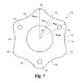
- FIG. 7 illustrates a front view of an adjustment nut body 700 .
- a drive train device 100 includes a slip clutch 102 .
- the slip clutch 102 has an adjustment nut 104 that can be manipulated to adjust the contact forces or normal forces between friction plates 106 and a driven member 108 .
- the driven member 108 is depicted as a sprocket, but can also take the form of a cog, gearwheel, pinion, sprocket, sheave or other mechanism producing or transferring rotational motion.
- a hub 110 extends along an axis A, representing the axis of rotation of the device 100 during operation. The hub 110 extends through the adjustment nut 104 , friction plates 106 , driven member 108 , and spring 112 .
- the spring 112 includes two compression springs 114 stacked one against the other.
- the spring 112 can have one or more compression springs 114 that apply biasing force toward the adjustment nut 104 .
- Drive train device 100 includes two friction plates 106 on opposite sides of the driven member 108 .
- the friction plates 106 include friction discs 116 and pressure plates 118 .
- the friction discs 116 are disposed between driven member 108 and its corresponding pressure plate 118 .
- a surface 119 , 120 of the friction discs 116 can be in contact with a respective surface 121 , 122 of the driven member 108 .
- the surfaces 119 , 120 of the friction discs 116 and surfaces 121 , 122 of the driven member 108 are annular flat surfaces.
- the surfaces 119 , 120 of the friction discs 116 and surfaces 121 , 122 of the driven member 108 can take different shapes including different complementary annular shapes.
- the adjustment nut 104 is in contact with one of the friction plates 106 .
- the adjustment nut 104 includes an adjustment nut body 124 and tensioning members 126 that extend through the adjustment nut body 124 in a direction parallel to the axis A, which direction is also referred to herein as the axial direction.
- the three tensioning members 126 are axially adjustable with respect to the adjustment nut body 124 and are in contact with the friction plate 106 closer to the nut body 122 .
- the adjustment nut 104 can be adjustably fixed with respect to hub in the rotational direction and in the axial direction.
- the adjustment nut 104 can be secured in a particular rotational and axial position with respect to the hub 110 .
- the adjustment nut 104 rotates with the hub 110 .
- the hub 110 and driven member 108 rotate at the same speed and when the drive train apparatus 100 is driven at torques having a value under which slippage occurs between the friction plates 106 and driven member 108 .
- the friction plates 106 can also be rotationally secured to the hub 110 , for example by incorporating a keyed hole through with a complementarily keyed hub 110 is inserted.
- the keyed hole and hub could prevent rotational motion of the plates 106 with respect to the hub 110 .
- the depicted driven member 108 remains rotationally free with respect to the hub 110 except for circumstances where the friction plates 106 are in contact with the driven member 108 with sufficient force.
- a collar can be inserted between the hub 110 and driven member 108 . Like the driven member 108 , the collar can also rotate about the hub 110 freely, or can be rotationally fixed with respect to the hub 110 , for example in a manner similar to the plates 106 .
- the driven member 108 rotates freely with respect to the hub 110 and intermediate collars.
- the spring 112 sits between a stop 130 and friction plate 106 .
- the stop 130 limits the movement of the spring 112 in the axial direction.
- the stop 130 is depicted including six radial protrusions 132 against which the spring 112 makes contact.
- the stop 130 supplies the opposing force against the biased spring 112 .
- a stop according to the present teachings can take other forms, too, such as a flange or other forms of radial protrusions at the end of the hub 110 .
- the tensioning members 126 are hex-headed threaded bolts that are inserted into threaded holes 140 at the lobes 150 .
- the lobes 150 accommodate the tensioning members 126 , and their placement, which is further from axis A than the profiled surfaces 160 , allows desired placement of the tensioning members 126 relative to the friction plates 106 while minimizing the overall amount of material in the nut body 124 .
- the profiled surfaces 160 between the lobes 150 have a reduced radius relative to the lobes 150 .
- the radially outer surface 170 defines, in part, both the lobes 150 and profiled surfaces 160 .
- the internal opening 180 of adjustment nut body 124 can be threaded to meet a threaded surface of a hub 110 .
- the adjustment nut 104 has three lobes 150 extending radially further from the axis of rotation A than the profiled surfaces 160 between the lobes 150 .
- An adjustment nut 104 according to the present teachings can have two or more lobes 150 , and according to one aspect of the present teachings has at least three lobes 150 .
- the radially outer surface 170 of the adjustment nut 104 defines the radially outermost location of the nut 104 from the axis A when viewing the nut 104 along the axis A of rotation.
- the radially outer surface 170 has a maximum distance from the axis of rotation A, R MAX , at the lobes 150 .
- a line segment from the axis of rotation A through the center of the threaded holes 140 to the point on the outer surface 170 furthest from the axis A measures R MAX .
- the adjustment nut 104 has the radius R MAX at each of the three lobes 150 .
- the lobes 150 and the lines labelled R MAX are about circumferentially equidistant from one another, spaced apart by 2 ⁇ /3 radians. The symmetric placement of the lobes 150 , and therefore of the tensioning members 126 , allows for more evenly distributed force applied to the pressure plate 118 .
- the outer surface 160 defines a shape symmetric over rotations of 2 ⁇ /3 radians about the axis A.
- the contour formed by the outer surface 170 as viewed along the axis A will appear the same before and after rotation of the nut 104 about A by 2 ⁇ /3 radians.
- the adjustment nut 104 can have an outer surface 170 having a shape that is n-fold symmetric, appearing the same after rotations of 2 ⁇ /n about the axis of rotation A.
- the three-fold symmetry of the nut body 124 corresponds to the symmetry over rotations of 2 ⁇ /3.
- the distance R( ⁇ ) is the radial distance from the axis A to the outer surface 170 at the angle ⁇ measured from the vertical line Z.
- R( ⁇ ) has a smaller value smaller than R MAX over the entire profiled surface 160 .
- R( ⁇ ) also has a smaller average value than R MAX over the entire profiled surface 160 , which average value can be determined by integrating the distance R( ⁇ ) over the domain of ⁇ .
- the profiled surface 160 need not have a distance R( ⁇ ) less than R MAX over the entire profiled surface 160 , but instead can have such a reduced radius surface over at least a portion of the outer surface 170 between the lobes 150 .
- the lobes 150 extend radially outwardly from the axis A relative to the adjacent profiled surfaces 160 .
- the adjustment nut 104 has a reduced radius at the profiled surfaces 160 relative to the lobes 150 .
- the smallest value of R( ⁇ ) over the outer surface 170 is R MIN , which occurs at each of the three profiled surfaces 160 , including where marked by lines R MIN .
- the lines R MIN are spaced equidistantly from each of the adjacent lines R MAX by an angular distance of ⁇ /3 radians, and equidistantly 2 ⁇ /3 radians from one another.
- the profiled surface 160 is defined in part by a portion of the outer surface 170 having a fixed radius R( ⁇ ) of R MIN as viewed along axis A over a range of angles ⁇ .
- the profiled surface 160 has a constant radial distance R MIN from the axis A between the inflections 162 , at which point the radius of the profiled surface 160 begins to increase as it transitions to the lobe 150 . Due to their fixed radius relative to axis A, the profiled surfaces are cylindrically shaped in the region between inflections 162 .
- Each of the profiled surfaces 160 has a radius R( ⁇ ) of R MIN over a range of about ⁇ /3 radians between adjacent lobes 150 . The total range of the three profiled surfaces 160 totals about ⁇ radians.
- the profiled surfaces 160 can have a reduced size and volume relative to the lobes 150 by several measures, including but not limited to having an average radius that is less than the peak value of the radius of the adjustment nut body 124 , having an average radius than is less than the average radius of the lobes 150 , having a minimum radius that is less than the peak value of the radius of the adjustment nut body 124 , or having a minimum radius that is less than the average value of the radius of the adjustment nut body 124 at lobes 150 .
- the profiled surfaces 160 can have a reduced radius relative to an individual lobe 150 or a combined measure of their radii from axis A.
- the reduction in total material in the nut 104 due to the shape of the profiled surfaces 160 can improve airflow to other components of the slip clutch 102 and allow heat to dissipate more quickly, which can in turn improve longevity of the overall drive train component 100 .
- the absence of additional material where the profiled surfaces 160 are located permits increased airflow through those regions, which would otherwise be blocked but for the profiled surfaces 160 .
- a fanning effect is also exhibited as the rotating lobes 150 and profiled surfaces 160 disturb the surrounding air.
- the lack of non-essential material at the profiled surfaces allows for convective heat dissipation rather than relying primarily on conductive and radiative dissipation.
- the adjustment nut body 124 can be formed from casting, machining, forging, and forming.
- the adjustment nut body 124 can be made partially or entirely from powdered metal, which can exhibit greater heat dissipation characteristics than certain solid metals such as cast iron. It should be noted that the adjustment nut body 124 can be made of a variety of materials, including but not limited to powdered or solid cast or machined metals.
- Assembly of the component 100 can include sliding the spring 112 to stop 130 , and then sliding one of the friction plates 106 onto the hub 110 , whether as an individual unit or separate friction disk 116 and pressure plate 118 , such that the friction disk 116 is contact with the driven member 108 and the pressure plate 118 is in contact with the springs.
- the friction plates 106 can have a keyed opening complementary to the hub 110 such that the plates 106 are rotationally fixed with respect to the hub 110 .
- the driven member 108 is then slid over the hub 110 , which can be followed by an additional friction plate 106 , again with the friction disk 116 facing and in contact with the driven member 108 , and the pressure plate 118 on the opposite side of the friction disk 116 relative to the driven member 108 .
- the adjustment nut 104 is then threaded over the end of the hub 110 , and rotationally secured with setscrew 128 , which can be screwed into an available spline on hub 110 .
- the nut 104 is also axially fixed due to the threaded interface with hub 110 . Fixed both axially and rotationally, the nut 104 can be adjusted to apply force in the axial direction against springs 112 . By tightening the tensioning members 126 the contact force increases, which increases the frictional force between the intervening components, and in particular between the friction discs 116 and driven member 108 .
- the nut 104 can be selectively placed along the hub 110 such that the tensioning members 126 can be adjusted, to press on the adjacent friction plate 106 with a desired force. As the tensioning members 126 are adjusted to provide greater or lesser force on the friction plate 106 , the spring 112 on the distal side of the hub 110 applies and equal and opposite force to its respective friction plate 106 .
- the driven member 108 can then be driven with an appropriate chain or belt, and the entire clutch 102 will rotate, transferring the rotational motion synchronously until a torque higher than the slippage threshold occurs, in which case the clutch will slip until the torque returns to a suitable level.
- the slippage torque can be increased by tightening the friction plates 106 against the driven member 108 , which can be done by tightening tensioning members 126 .
- Slippage torque can be decreased by lowering the contact force between the friction plates 106 and the driven member 108 by loosening the tensioning members 126 of the adjustment nut 104 .
- FIG. 6 depicts an adjustment nut body 600 where the lobes 602 are block shaped protrusions extending further radially from an axis A than any point on adjacent profiled surfaces 604 .
- Each of the lobes 602 includes an end surface 606 that can be an arcuate surface a constant distance R MAX from axis A, and sides 608 that can be collinear with lines extending from the axis A.
- the lobes 608 need not be this specific shape and can alternatively be square, rectangular, trapezoidal, or other geometric shapes.
- Holes 610 permit insertion of tensioning members such as members 126 at the lobes 602 .
- the profiled surfaces 604 are cylindrical in shape, having a radius of R MIN measured from axis A over the entirety of each profiled surface 604 .
- the profiled surfaces 604 need not be so shaped, and could take other shapes, such as other curved shapes having a variable distance R( ⁇ ) smaller than R MAX between the lobes 602 .
- the lobes 602 and profiled surfaces 604 depicted in FIG. 6 are clearly demarcated, with the profiled surface 604 ending at the sides 608 , at which point the lobes 602 begin. However, the division between profiled surfaces 604 and lobes 602 need not be so clearly demarked.
- a transition surface 190 can bridge the area between and overlap with profiled surfaces and lobes, such as profiled surfaces 160 and lobes 150 .
- lobes such as lobes 602 can be configured to hold more than one tension member 126 .
- another adjustment nut 700 includes three lobes 702 , each having a hole 704 for insertion of a tensioning member such as member 126 .
- Profiled surfaces 706 and protrusions 708 are found between the lobes 702 and are defined at least in part by radially outer surface 710 .
- the lobes 702 extend outwardly from adjacent profiled surfaces 706 and have a maximum radius R( ⁇ ) of R LOBE .
- the profiled surfaces 706 have a radius R( ⁇ ) that is less than R LOBE , including where the radius is R MIN , the minimum distance from axis A to the outer surface 710 .
- the profiled surfaces 706 are interrupted by protrusions 708 that extend outwardly by a maximum distance R PROT , which distance can be less than, equal to or be greater than R LOBE . As shown in FIG. 7 , two profiled surfaces 706 can be found between lobes 702 with a reduced radius relative to an adjacent lobe 702 . Moreover, according to the present teachings, two or more profiled surfaces, such as profiled surfaces 706 , can be found between lobes, such as lobes 702 , with a reduced radius relative to a lobe.
- adjustment nut 104 provided increased airflow relative to prior designs, which did not include profiled surfaces 160 but instead had an annularly shaped adjustment nut with a generally cylindrical outer surfaces. Further, use of the nut 104 resulted in lower operating temperatures measured at the friction plates 106 , in one case reducing operating temperature from 147° to 116° Fahrenheit.
Landscapes
- Engineering & Computer Science (AREA)
- General Engineering & Computer Science (AREA)
- Mechanical Engineering (AREA)
- Mechanical Operated Clutches (AREA)
Abstract
Description
Claims (15)
Priority Applications (1)
| Application Number | Priority Date | Filing Date | Title |
|---|---|---|---|
| US14/874,552 US9845830B2 (en) | 2015-10-05 | 2015-10-05 | Profiled adjustment nut |
Applications Claiming Priority (1)
| Application Number | Priority Date | Filing Date | Title |
|---|---|---|---|
| US14/874,552 US9845830B2 (en) | 2015-10-05 | 2015-10-05 | Profiled adjustment nut |
Publications (2)
| Publication Number | Publication Date |
|---|---|
| US20170097050A1 US20170097050A1 (en) | 2017-04-06 |
| US9845830B2 true US9845830B2 (en) | 2017-12-19 |
Family
ID=58446703
Family Applications (1)
| Application Number | Title | Priority Date | Filing Date |
|---|---|---|---|
| US14/874,552 Expired - Fee Related US9845830B2 (en) | 2015-10-05 | 2015-10-05 | Profiled adjustment nut |
Country Status (1)
| Country | Link |
|---|---|
| US (1) | US9845830B2 (en) |
Citations (5)
| Publication number | Priority date | Publication date | Assignee | Title |
|---|---|---|---|---|
| US2753703A (en) * | 1953-05-25 | 1956-07-10 | Morse Chain Co | Clutch with slip indicating device |
| US2939301A (en) * | 1959-03-09 | 1960-06-07 | Int Harvester Co | Warning device |
| US3111824A (en) * | 1961-10-30 | 1963-11-26 | Dodge Mfg Corp | Torque limiting mechanism |
| US3605443A (en) * | 1969-08-04 | 1971-09-20 | Interlake Steel Corp | Torque limiter |
| US20150114785A1 (en) * | 2013-10-28 | 2015-04-30 | Gkn Driveline International Gmbh | Plate carrier |
-
2015
- 2015-10-05 US US14/874,552 patent/US9845830B2/en not_active Expired - Fee Related
Patent Citations (5)
| Publication number | Priority date | Publication date | Assignee | Title |
|---|---|---|---|---|
| US2753703A (en) * | 1953-05-25 | 1956-07-10 | Morse Chain Co | Clutch with slip indicating device |
| US2939301A (en) * | 1959-03-09 | 1960-06-07 | Int Harvester Co | Warning device |
| US3111824A (en) * | 1961-10-30 | 1963-11-26 | Dodge Mfg Corp | Torque limiting mechanism |
| US3605443A (en) * | 1969-08-04 | 1971-09-20 | Interlake Steel Corp | Torque limiter |
| US20150114785A1 (en) * | 2013-10-28 | 2015-04-30 | Gkn Driveline International Gmbh | Plate carrier |
Non-Patent Citations (2)
| Title |
|---|
| Excerpt titled "Features/Benefits; Torque-Tamer" from Baldor-Dodge 2010 PT Components Engineering Catalog; Baldor Electric Company; Aug. 2010. |
| Instruction Manual for Torque-Tamer(TM); Baldor Electric Company; Mar. 2011. |
Also Published As
| Publication number | Publication date |
|---|---|
| US20170097050A1 (en) | 2017-04-06 |
Similar Documents
| Publication | Publication Date | Title |
|---|---|---|
| EP2984359B1 (en) | Isolator decoupler | |
| KR101643029B1 (en) | Pulley with asymmetric torque-sensitive clutching | |
| CA2723044A1 (en) | Pulley with torque-sensitive clutching | |
| CN203702922U (en) | Diagonal bracing type overrun clutch, coupler, hinge and transmission wheel | |
| US6958025B2 (en) | Belt tensioner for use with torque converter | |
| US20140113732A1 (en) | Power Transmission Device And Compressor Equipped With Power Transmission Device | |
| US9845830B2 (en) | Profiled adjustment nut | |
| KR100649466B1 (en) | Belt mounting device | |
| US8978856B2 (en) | Over-torque protector device for a compressor | |
| CN209654464U (en) | A kind of antioverloading shaft coupling | |
| US11708886B2 (en) | Single spring, torsionally compliant, overrunning decoupler | |
| WO2014193293A1 (en) | Centrifugal clutch arrangement | |
| CN1231649A (en) | Overload Clutch Device | |
| CN212202904U (en) | Locking strip for limiting torque | |
| EP2707626B1 (en) | Improved over-torque protector device for a compressor | |
| CN105736592A (en) | Frictional coupler | |
| JP4196967B2 (en) | Power transmission mechanism | |
| US7578759B2 (en) | Torque limiting mechanism | |
| US9488232B1 (en) | Externally adjustable clutch | |
| US2569593A (en) | Clutch head | |
| CN111486184A (en) | Locking strip for limiting torque | |
| RU135038U1 (en) | ELASTIC COUPLING | |
| FR3086193B1 (en) | CENTRIFUGATION CLAMPING DEVICE | |
| KR102067138B1 (en) | Power transmission device of comppressor | |
| WO2014157276A1 (en) | Motive-power transmission device |
Legal Events
| Date | Code | Title | Description |
|---|---|---|---|
| AS | Assignment |
Owner name: ABB TECHNOLOGY AG, SWITZERLAND Free format text: ASSIGNMENT OF ASSIGNORS INTEREST;ASSIGNORS:VITOU, ALEXANDER BRIAN;KUCKHOFF, THOMAS ERIC;REEL/FRAME:038447/0847 Effective date: 20150831 |
|
| AS | Assignment |
Owner name: ABB SCHWEIZ AG, SWITZERLAND Free format text: MERGER;ASSIGNOR:ABB TECHNOLOGY LTD.;REEL/FRAME:040621/0853 Effective date: 20160509 |
|
| STCF | Information on status: patent grant |
Free format text: PATENTED CASE |
|
| MAFP | Maintenance fee payment |
Free format text: PAYMENT OF MAINTENANCE FEE, 4TH YEAR, LARGE ENTITY (ORIGINAL EVENT CODE: M1551); ENTITY STATUS OF PATENT OWNER: LARGE ENTITY Year of fee payment: 4 |
|
| AS | Assignment |
Owner name: DODGE ACQUISITION CO., CONNECTICUT Free format text: ASSIGNMENT OF ASSIGNORS INTEREST;ASSIGNORS:ABB SCHWEIZ AG;ABB MOTORS AND MECHANICAL INC.;ABB ASEA BROWN BOVERI LTD;REEL/FRAME:058001/0201 Effective date: 20211101 |
|
| AS | Assignment |
Owner name: WELLS FARGO BANK, NATIONAL ASSOCIATION, AS COLLATERAL AGENT, COLORADO Free format text: SECURITY INTEREST;ASSIGNOR:DODGE ACQUISITION CO.;REEL/FRAME:058099/0286 Effective date: 20211101 |
|
| AS | Assignment |
Owner name: DODGE INDUSTRIAL, INC., CONNECTICUT Free format text: ASSIGNMENT OF ASSIGNORS INTEREST;ASSIGNORS:ABB SCHWEIZ AG;ABB ASEA BROWN BOVERI LTD;ABB MOTORS AND MECHANICAL INC.;AND OTHERS;SIGNING DATES FROM 20220308 TO 20220322;REEL/FRAME:059859/0375 |
|
| FEPP | Fee payment procedure |
Free format text: MAINTENANCE FEE REMINDER MAILED (ORIGINAL EVENT CODE: REM.); ENTITY STATUS OF PATENT OWNER: LARGE ENTITY |
|
| LAPS | Lapse for failure to pay maintenance fees |
Free format text: PATENT EXPIRED FOR FAILURE TO PAY MAINTENANCE FEES (ORIGINAL EVENT CODE: EXP.); ENTITY STATUS OF PATENT OWNER: LARGE ENTITY |
|
| STCH | Information on status: patent discontinuation |
Free format text: PATENT EXPIRED DUE TO NONPAYMENT OF MAINTENANCE FEES UNDER 37 CFR 1.362 |
|
| FP | Lapsed due to failure to pay maintenance fee |
Effective date: 20251219 |