US9838104B1 - System and method for fast compression of OFDM channel state information (CSI) based on constant frequency sinusoidal approximation - Google Patents
System and method for fast compression of OFDM channel state information (CSI) based on constant frequency sinusoidal approximation Download PDFInfo
- Publication number
- US9838104B1 US9838104B1 US15/434,704 US201715434704A US9838104B1 US 9838104 B1 US9838104 B1 US 9838104B1 US 201715434704 A US201715434704 A US 201715434704A US 9838104 B1 US9838104 B1 US 9838104B1
- Authority
- US
- United States
- Prior art keywords
- csi
- vector
- receiver
- configurations
- base
- Prior art date
- Legal status (The legal status is an assumption and is not a legal conclusion. Google has not performed a legal analysis and makes no representation as to the accuracy of the status listed.)
- Active
Links
Images
Classifications
-
- H—ELECTRICITY
- H04—ELECTRIC COMMUNICATION TECHNIQUE
- H04B—TRANSMISSION
- H04B7/00—Radio transmission systems, i.e. using radiation field
- H04B7/02—Diversity systems; Multi-antenna system, i.e. transmission or reception using multiple antennas
- H04B7/04—Diversity systems; Multi-antenna system, i.e. transmission or reception using multiple antennas using two or more spaced independent antennas
- H04B7/06—Diversity systems; Multi-antenna system, i.e. transmission or reception using multiple antennas using two or more spaced independent antennas at the transmitting station
- H04B7/0613—Diversity systems; Multi-antenna system, i.e. transmission or reception using multiple antennas using two or more spaced independent antennas at the transmitting station using simultaneous transmission
- H04B7/0615—Diversity systems; Multi-antenna system, i.e. transmission or reception using multiple antennas using two or more spaced independent antennas at the transmitting station using simultaneous transmission of weighted versions of same signal
- H04B7/0619—Diversity systems; Multi-antenna system, i.e. transmission or reception using multiple antennas using two or more spaced independent antennas at the transmitting station using simultaneous transmission of weighted versions of same signal using feedback from receiving side
- H04B7/0621—Feedback content
- H04B7/0626—Channel coefficients, e.g. channel state information [CSI]
-
- H—ELECTRICITY
- H03—ELECTRONIC CIRCUITRY
- H03M—CODING; DECODING; CODE CONVERSION IN GENERAL
- H03M7/00—Conversion of a code where information is represented by a given sequence or number of digits to a code where the same, similar or subset of information is represented by a different sequence or number of digits
- H03M7/30—Compression; Expansion; Suppression of unnecessary data, e.g. redundancy reduction
- H03M7/3082—Vector coding
-
- H—ELECTRICITY
- H04—ELECTRIC COMMUNICATION TECHNIQUE
- H04B—TRANSMISSION
- H04B7/00—Radio transmission systems, i.e. using radiation field
- H04B7/02—Diversity systems; Multi-antenna system, i.e. transmission or reception using multiple antennas
- H04B7/04—Diversity systems; Multi-antenna system, i.e. transmission or reception using multiple antennas using two or more spaced independent antennas
- H04B7/06—Diversity systems; Multi-antenna system, i.e. transmission or reception using multiple antennas using two or more spaced independent antennas at the transmitting station
- H04B7/0613—Diversity systems; Multi-antenna system, i.e. transmission or reception using multiple antennas using two or more spaced independent antennas at the transmitting station using simultaneous transmission
- H04B7/0615—Diversity systems; Multi-antenna system, i.e. transmission or reception using multiple antennas using two or more spaced independent antennas at the transmitting station using simultaneous transmission of weighted versions of same signal
- H04B7/0619—Diversity systems; Multi-antenna system, i.e. transmission or reception using multiple antennas using two or more spaced independent antennas at the transmitting station using simultaneous transmission of weighted versions of same signal using feedback from receiving side
- H04B7/0658—Feedback reduction
-
- H—ELECTRICITY
- H04—ELECTRIC COMMUNICATION TECHNIQUE
- H04B—TRANSMISSION
- H04B7/00—Radio transmission systems, i.e. using radiation field
- H04B7/02—Diversity systems; Multi-antenna system, i.e. transmission or reception using multiple antennas
- H04B7/04—Diversity systems; Multi-antenna system, i.e. transmission or reception using multiple antennas using two or more spaced independent antennas
- H04B7/08—Diversity systems; Multi-antenna system, i.e. transmission or reception using multiple antennas using two or more spaced independent antennas at the receiving station
- H04B7/0837—Diversity systems; Multi-antenna system, i.e. transmission or reception using multiple antennas using two or more spaced independent antennas at the receiving station using pre-detection combining
- H04B7/0842—Weighted combining
- H04B7/0848—Joint weighting
- H04B7/0854—Joint weighting using error minimizing algorithms, e.g. minimum mean squared error [MMSE], "cross-correlation" or matrix inversion
-
- H—ELECTRICITY
- H04—ELECTRIC COMMUNICATION TECHNIQUE
- H04L—TRANSMISSION OF DIGITAL INFORMATION, e.g. TELEGRAPHIC COMMUNICATION
- H04L1/00—Arrangements for detecting or preventing errors in the information received
- H04L1/0001—Systems modifying transmission characteristics according to link quality, e.g. power backoff
- H04L1/0006—Systems modifying transmission characteristics according to link quality, e.g. power backoff by adapting the transmission format
-
- H—ELECTRICITY
- H04—ELECTRIC COMMUNICATION TECHNIQUE
- H04L—TRANSMISSION OF DIGITAL INFORMATION, e.g. TELEGRAPHIC COMMUNICATION
- H04L27/00—Modulated-carrier systems
- H04L27/26—Systems using multi-frequency codes
- H04L27/2601—Multicarrier modulation systems
- H04L27/2626—Arrangements specific to the transmitter only
- H04L27/2627—Modulators
- H04L27/2634—Inverse fast Fourier transform [IFFT] or inverse discrete Fourier transform [IDFT] modulators in combination with other circuits for modulation
-
- H—ELECTRICITY
- H03—ELECTRONIC CIRCUITRY
- H03M—CODING; DECODING; CODE CONVERSION IN GENERAL
- H03M7/00—Conversion of a code where information is represented by a given sequence or number of digits to a code where the same, similar or subset of information is represented by a different sequence or number of digits
- H03M7/30—Compression; Expansion; Suppression of unnecessary data, e.g. redundancy reduction
- H03M7/60—General implementation details not specific to a particular type of compression
- H03M7/6017—Methods or arrangements to increase the throughput
- H03M7/6023—Parallelization
-
- H—ELECTRICITY
- H03—ELECTRONIC CIRCUITRY
- H03M—CODING; DECODING; CODE CONVERSION IN GENERAL
- H03M7/00—Conversion of a code where information is represented by a given sequence or number of digits to a code where the same, similar or subset of information is represented by a different sequence or number of digits
- H03M7/30—Compression; Expansion; Suppression of unnecessary data, e.g. redundancy reduction
- H03M7/60—General implementation details not specific to a particular type of compression
- H03M7/6047—Power optimization with respect to the encoder, decoder, storage or transmission
-
- H—ELECTRICITY
- H04—ELECTRIC COMMUNICATION TECHNIQUE
- H04L—TRANSMISSION OF DIGITAL INFORMATION, e.g. TELEGRAPHIC COMMUNICATION
- H04L27/00—Modulated-carrier systems
- H04L27/26—Systems using multi-frequency codes
- H04L27/2601—Multicarrier modulation systems
-
- H—ELECTRICITY
- H04—ELECTRIC COMMUNICATION TECHNIQUE
- H04W—WIRELESS COMMUNICATION NETWORKS
- H04W84/00—Network topologies
- H04W84/02—Hierarchically pre-organised networks, e.g. paging networks, cellular networks, WLAN [Wireless Local Area Network] or WLL [Wireless Local Loop]
- H04W84/10—Small scale networks; Flat hierarchical networks
- H04W84/12—WLAN [Wireless Local Area Networks]
Definitions
- Wi-Fi Wireless Fidelity
- MIMO Multiple-Input-Multiple-Output
- MU-MIMO Multi-User MIMO
- the CSI for an antenna pair is a vector of complex numbers representing the channel coefficients of the OFDM subcarriers, and is the key to calculating the modulation parameters for the data transmission.
- the CSI is typically measured at the receiver and is transmitted back to the sender, which requires significant overhead.
- the full CSI for a single antenna pair on a 20 MHz channel has 64 complex numbers; if there are 9 antenna pairs, the full CSI has 9 vectors with 576 complex numbers which may exceed 1000 bytes.
- the Wi-Fi standard defines options to compress the CSI, such as reducing the quantization accuracy or the number of subcarriers in the feedback, or using the Given's rotation on the V matrix after the Singular Value Decomposition (SVD) of the CSI matrix.
- these methods either reduce the accuracy of the CSI, or only achieve modest compression ratios. For example, a 3 by 3 complex V matrix can only be compressed into 6 real numbers, at a compression ratio of 3.
- the need for CSI feedback reduction in wireless networks in general is well known in the art.
- the present invention provides a system and method, referred to as CSIApx, which is a very fast and lightweight method to compress the Channel State Information (CSI) of Wi-Fi networks.
- CSIApx approximates the CSI vector as the linear combination of a small number of base sinusoids on constant frequencies and uses the complex coefficients of the base sinusoids as the compressed CSI. While it is well-known that the CSI vector can be represented as the linear combination of sinusoids, fixing the frequencies of the base sinusoids is the key novelty of CSIApx, which is guided by the mathematical finding that almost any sinusoid can be approximated by the same set of base sinusoids with small bounded error.
- CSIApx enjoys very low computation complexity, because the key steps in the compression can be pre-computed. Extensive testing of CSIApx with both experimental and synthesized Wi-Fi channel data confirms that CSIApx can achieve very good compression ratio with little loss of accuracy.
- the present invention provides, a method for compressing channel state information (CSI) of a wireless channel, which includes, receiving, at a receiver of a wireless communication system, an orthogonal frequency division multiplexing (OFDM) wireless signal over a wireless channel and measuring at a receiver of a wireless communication system comprising one or more antenna pair, a channel state information (CSI) vector of the wireless channel from the received OFDM wireless signal for each antenna pair, wherein the CSI vector is an N by 1 vector of complex numbers and wherein each complex number represents an amplitude and a phase of one of N orthogonal frequency division multiplexing (OFDM) subcarriers of the wireless channel.
- OFDM orthogonal frequency division multiplexing
- the method further includes, accessing a plurality of configurations stored at the receiver, wherein each of the plurality of configurations “u”, identifies a set of P u base sinusoid vectors on constant frequencies and wherein P u is the order of the configuration and is equal to the number of complex numbers of the compressed CSI if configuration u is selected, calculating, for each of the plurality of configurations, a dot product of the N by 1 CSI vector and a conjugate of each P u base sinusoid vector identified by the selected configuration to generate a P u by 1 projection vector, calculating, for each of the plurality of configurations, a product of a constant P u by P u matrix stored at the receiver and the P u by 1 projection vector to generate a P u by 1 coefficient vector and calculating, for each of the plurality of configurations, a minimum squared error (MSE) fit with the P u by 1 coefficient vector on L evenly-spaced locations where L is smaller than N, by multiplying each of the P u
- the final step of the compression is to select configuration u and use its P u by 1 coefficient vector as the output, if the total fit residual of the MSE fit of configuration u is below a predetermined threshold times the minimum fit residual among all configurations, and u is such a configuration with the lowest order.
- the compressed CSI is transmitted to the transmitter of the wireless communication system, which may decompress the CSI by computing a linear combination of the base sinusoids, based upon the decompressed CSI.
- the present invention provides a wireless communication system for compressing channel state information (CSI) of a wireless system.
- the system of the present invention includes, a receiver for receiving an orthogonal frequency division multiplexing (OFDM) wireless signal over a wireless channel.
- the receiver is configured for measuring a channel state information (CSI) vector of the wireless channel from the received OFDM wireless signal, wherein the CSI vector for each antenna pair is an N by 1 vector of complex numbers and wherein each complex number represents an amplitude and a phase of one of N OFDM subcarriers of the wireless channel, accessing a plurality of configurations stored at the receiver, wherein each of the plurality of configurations “u” identifies a set of P u base sinusoid vectors on constant frequencies and wherein P u is the order of the configuration and is equal to the number of complex numbers of the compressed CSI if configuration u is selected.
- CSI channel state information
- the receiver is further configured for calculating, for each of the plurality of configurations, a dot product of the N by 1 CSI vector and a conjugate of each P u base sinusoid vector identified by the selected configuration to generate a P u by 1 projection vector, for calculating, for each of the plurality of configurations, for each of the plurality of configurations, a product of a constant P u by P u matrix stored at the receiver and the P u by 1 projection vector to generate a P u by 1 coefficient vector, for calculating, for each of the plurality of configurations, a minimum squared error (MSE) fit with the P u by 1 coefficient vector on L evenly-spaced locations where L is smaller than N, by multiplying each of the P u base sinusoids with the corresponding coefficient in the coefficient vector and taking the summation, at each of the L evenly-spaced locations.
- MSE minimum squared error
- the receiver is further configured for selecting configuration u and use its P u by 1 coefficient vector as the output, if the total fit residual of the MSE fit of configuration u is below a predetermined threshold times the minimum fit residual among all configurations, and u is such a configuration with the lowest order.
- the compressed CSI is transmitted to the transmitter of the wireless communication system, which may decompress the CSI by computing a linear combination of the base sinusoids, based upon the decompressed CSI.
- the present invention provides a non-transitory computer-readable recording medium storing a computer program used for executing a channel state information (CSI) compressing operation of an Orthogonal Frequency Division Multiplexing (OFDM) wireless channel of a wireless communication system.
- CSI channel state information
- OFDM Orthogonal Frequency Division Multiplexing
- the computer program causes a wireless communication system to receive, at a receiver of the wireless communication system, an OFDM wireless signal over a wireless channel, to measure, at a receiver of the wireless communication system, a channel state information (CSI) vector of the wireless channel from the received OFDM wireless signal for each antenna pair, wherein the CSI vector is an N by 1 vector of complex numbers and wherein each complex number represents an amplitude and a phase of one of N OFDM subcarriers of the wireless channel and to access a plurality of configurations stored at the receiver, wherein each of the plurality of configurations “u” identifies a set of P u base sinusoid vectors on constant frequencies and wherein P u is the order of the configuration and is equal to the number of complex numbers of the compressed CSI if configuration u is selected.
- CSI channel state information
- the computer program further causes the receiver of the wireless communication system to calculate, for each of the plurality of configurations, a dot product of the N by 1 CSI vector and a conjugate of each P u base sinusoid vector identified by the selected configuration to generate a P u by 1 projection vector, to calculate, for each of the plurality of configurations, a product of a constant P u by P u matrix stored at the receiver and the P u by 1 projection vector to generate a P u by 1 coefficient vector, and to calculate, for each of the plurality of configurations, a minimum squared error (MSE) fit with the P u by 1 coefficient vector on L evenly-spaced locations where L is smaller than N, by multiplying each of the P u base sinusoids with the corresponding coefficient in the coefficient vector and taking the summation, at each of the L evenly-spaced locations.
- MSE minimum squared error
- the computer program further causes the receiver of the wireless communication system to select configuration u and use its P u by 1 coefficient vector as the output, if the total fit residual of the MSE fit of configuration u is below a predetermined threshold times the minimum fit residual among all configurations, and u is such a configuration with the lowest order.
- the computer program further causes the receiver to transmit the compressed CSI to the transmitter of the wireless communication system.
- the computer program further causes the transmitter of the wireless communication system to decompress the CSI by computing a linear combination of the base sinusoids, based upon the compressed CSI.
- the system and method of the present invention provides a novel CSI compression method for wireless networks based upon a rigid mathematical foundation which provides, a high compression ratio with a low loss of accuracy, a very low computation complexity which is suitable for hardware implementation, a small range of compressed data that is easy to quantize and to transmit and a solution that is resistant to noise in the channel.
- the system and method employing the CSIApx technology in accordance with the present invention serves as a strong candidate for a CSI compression methodology for future wireless protocols to be implemented in hardware, and significantly improve the capability of the wireless transmitter to acquire the most recent CSI and achieve higher transmission speed.
- a novel system and method to compress the CSI vector in a wireless transceiver is described and referred to herein as CSIApx.
- the present invention provides an improved system and method for compressing the CSI for OFDM wireless signals that is accurate and computationally easy to implement.
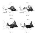
- FIG. 1A is a graphical illustration of the bound of the coefficients with an order of 5 of Direct Fit, in accordance with an embodiment of the present invention.
- FIG. 1B is a graphical illustration of the bound of the coefficients with an order of 7 of Direct Fit, in accordance with an embodiment of the present invention.
- FIG. 1C is a graphical illustration of the bound of the coefficients with an order of 11 of Direct Fit, in accordance with an embodiment of the present invention.
- FIG. 1D is a graphical illustration of the bound of the coefficients with an order of 16 of Direct Fit, in accordance with an embodiment of the present invention.
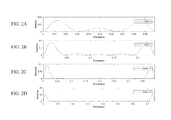
- FIG. 2A is a graphical illustration of the fit residual of the Direct Fit for a single target sinusoid with unit amplitude matched with an order of 4, in accordance with an embodiment of the present invention.
- FIG. 2B is a graphical illustration of the fit residual of the Direct Fit for a single target sinusoid with unit amplitude matched with an order of 6, in accordance with an embodiment of the present invention.
- FIG. 2C is a graphical illustration of the fit residual of the Direct Fit for a single target sinusoid with unit amplitude matched with an order of 10, in accordance with an embodiment of the present invention.
- FIG. 2D is a graphical illustration of the fit residual of the Direct Fit for a single target sinusoid with unit amplitude matched with an order of 16, in accordance with an embodiment of the present invention.
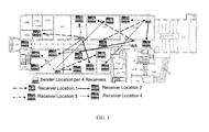
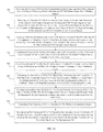
- FIG. 3 illustrates locations of receivers and senders in various experimental locations, in accordance with embodiments of the present invention.
- FIG. 4 is a graphical illustration of the absolute values of some raw CSI vectors, in accordance with embodiments of the present invention.
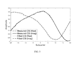
- FIG. 5 is a graphical illustration of a typical fit by CSIApx in accordance with embodiments of the present invention, where it can be seen that the fitted curve follows closely to the actual CSI.
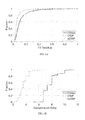
- FIG. 6A is a graphical illustration of the Cumulative Density Function (CDF) of the total fit residual of all 4 antenna pairs in 7923 CSI measurements, in accordance with an embodiment of the present invention.
- CDF Cumulative Density Function
- FIG. 6B is a graphical illustration of the compression ratio, defined as the ratio of the number of real numbers in the CSI vector over that needed by a compression method to describe the sinusoids, noting that a complex number consists of two real numbers, in accordance with an embodiment of the present invention.
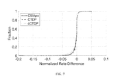
- FIG. 7 is a graphical illustration of the CDF of the normalized rate difference in accordance with an embodiment of the present invention, where it can be seen that the rate difference with CSIApx is usually very small.
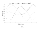
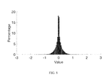
- FIG. 8 illustrates the distribution of the real and imaginary parts of the coefficients found by CSIApx for the strongest antenna pair in each test case, in accordance with an embodiment of the present invention.
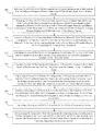
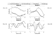
- FIG. 9A is a graphical illustration of a typical fit by CSIApx in a typical indoor environment with around 100 ns delay spread, in accordance with an embodiment of the present invention.
- FIG. 9B is a graphical illustration of a typical fit by CSIApx in a typical indoor environment with around 200 ns delay spread, in accordance with an embodiment of the present invention.
- FIG. 9C is a graphical illustration of a typical fit by CSIApx in a typical indoor environment with around 400 ns delay spread, in accordance with an embodiment of the present invention.
- FIG. 9D is a graphical illustration of a typical fit by CSIApx in a typical indoor environment with around 800 ns delay spread, in accordance with an embodiment of the present invention.
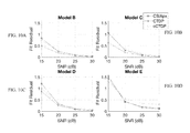
- FIG. 10A is a graphical illustration of the mean of the total fit residual of all antenna pairs in a typical indoor environment with around 100 ns delay spread, in accordance with an embodiment of the present invention.
- FIG. 10B is a graphical illustration of the mean of the total fit residual of all antenna pairs in a typical indoor environment with around 200 ns delay spread, in accordance with an embodiment of the present invention.
- FIG. 10C is a graphical illustration of the mean of the total fit residual of all antenna pairs in a typical indoor environment with around 400 ns delay spread, in accordance with an embodiment of the present invention.
- FIG. 10D is a graphical illustration of the mean of the total fit residual of all antenna pairs in a typical indoor environment with around 800 ns delay spread, in accordance with an embodiment of the present invention.
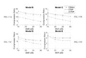
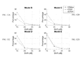
- FIG. 11A is a graphical illustration of the average compression ratios in a typical indoor environment with around 100 ns delay spread, in accordance with an embodiment of the present invention.
- FIG. 11B is a graphical illustration of the average compression ratios in a typical indoor environment with around 200 ns delay spread, in accordance with an embodiment of the present invention.
- FIG. 11C is a graphical illustration of the average compression ratios in a typical indoor environment with around 400 ns delay spread, in accordance with an embodiment of the present invention.
- FIG. 11D is a graphical illustration of the average compression ratios in a typical indoor environment with around 800 ns delay spread, in accordance with an embodiment of the present invention.
- FIG. 12A is a graphical illustration of the percentage of cases that the normalized rate differences are above 3% or lower than ⁇ 3% for an MU-MIMO rate in a typical indoor environment with around 100 ns delay spread, in accordance with an embodiment of the present invention.
- FIG. 12B is a graphical illustration of the percentage of cases that the normalized rate differences are above 3% or lower than ⁇ 3% for an MU-MIMO rate in a typical indoor environment with around 200 ns delay spread, in accordance with an embodiment of the present invention.
- FIG. 12C is a graphical illustration of the percentage of cases that the normalized rate differences are above 3% or lower than ⁇ 3% for an MU-MIMO rate in a typical indoor environment with around 400 ns delay spread, in accordance with an embodiment of the present invention.
- FIG. 12D is a graphical illustration of the percentage of cases that the normalized rate differences are above 3% or lower than ⁇ 3% for an MU-MIMO rate in a typical indoor environment with around 800 ns delay spread, in accordance with an embodiment of the present invention.
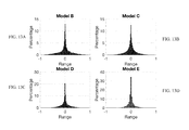
- FIG. 13A shows the distribution of the fit coefficients by CSIApx for the strongest antenna pair in a typical indoor environment with around 100 ns delay spread, in accordance with an embodiment of the present invention.
- FIG. 13B shows the distribution of the fit coefficients by CSIApx for the strongest antenna pair in a typical indoor environment with around 200 ns delay spread, in accordance with an embodiment of the present invention.
- FIG. 13C shows the distribution of the fit coefficients by CSIApx for the strongest antenna pair in a typical indoor environment with around 400 ns delay spread, in accordance with an embodiment of the present invention.
- FIG. 13D shows the distribution of the fit coefficients by CSIApx for the strongest antenna pair in a typical indoor environment with around 800 ns delay spread, in accordance with an embodiment of the present invention.
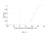
- FIG. 14 is a graphical illustration of the potential improvement utilizing Huffman Coding in addition to CSIApx, in accordance with an embodiment of the present invention.
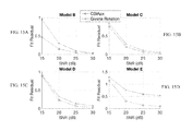
- FIG. 15A is a graphical illustration of the comparison between CSIApx and Givens rotation on the model data in a typical indoor environment with around 100 ns delay spread, in accordance with an embodiment of the present invention.
- FIG. 15B is a graphical illustration of the comparison between CSIApx and Givens rotation on the model data in a typical indoor environment with around 200 ns delay spread, in accordance with an embodiment of the present invention.
- FIG. 15C is a graphical illustration of the comparison between CSIApx and Givens rotation on the model data in a typical indoor environment with around 400 ns delay spread, in accordance with an embodiment of the present invention.
- FIG. 15D is a graphical illustration of the comparison between CSIApx and Givens rotation on the model data in a typical indoor environment with around 800 ns delay spread, in accordance with an embodiment of the present invention.
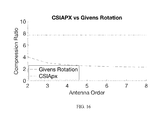
- FIG. 16 is a graphical illustration of the compression ratio for the experimental data, in accordance with an embodiment of the present invention.
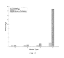
- FIG. 17 is a graphical illustrating of a comparison of the data rate achieved in a MU-MIMO setting from both CSIApx and Givens Rotation, showing the percentage of cases where the normalized rate differences, in accordance with an embodiment of the present invention.
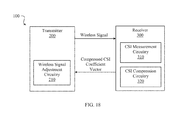
- FIG. 18 is a block diagram illustrating a structure of a communication system with channel state information (CSI) feedback, according to an embodiment of the present invention.
- CSI channel state information
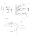
- FIG. 19A is a diagram illustrating a first step of the functionality of the CSI compression circuitry of the receiver of the wireless communication system, in accordance with an embodiment of the present invention.
- FIG. 19B is a diagram illustrating a second step of the functionality of the CSI compression circuitry of the receiver of the wireless communication system, in accordance with an embodiment of the present invention.
- FIG. 19C is a diagram illustrating a third step of the functionality of the CSI compression circuitry of the receiver of the wireless communication system, in accordance with an embodiment of the present invention.
- FIG. 20 is a flow diagram illustrating a method for compression the CSI in a wireless communication system, in accordance with an embodiment of the present invention.
- OFDM is the choice of modulation for broadband wireless networks today.
- entire communication frequency bandwidth is divided into equal size chunks, where the center of each chunk is called a subcarrier.
- a subcarrier can be considered as a pure sinusoid on a certain frequency, the amplitude and phase of which are set based on the values of the data bits.
- the CSI of a subcarrier is basically the amplitude and phase of the subcarrier observed by the receiver, when the sender transmits the unchanged subcarrier. If there is only one path from the sender to the receiver, the phases of the CSI of adjacent subcarriers will differ by the same amount, which is the phase difference due to the difference in frequencies over the same path length. Therefore, the CSI of all subcarriers will be a sinusoid.
- a typical wireless environment has multiple paths, therefore the CSI is the summation of multiple sinusoids.
- a target sinusoid on frequency g can be approximated as the linear combination of P base sinusoids, within certain error, under certain conditions. Therefore, the summation of many sinusoids, such as the CSI vector, can still be approximated as the linear combination of only P base sinusoids.
- the existence of polynomial approximation of sinusoids is used, such as those according to the Taylor series expansion, as a stepping stone. That is, if the target sinusoid can be approximated by a polynomial of degree P ⁇ 1, within certain error, it can also be approximated by P base sinusoids, within comparable error, because coefficients for the base sinusoids can be found by solving a linear system guaranteed to be nonsingular and the coefficients are bounded by constants.
- the sinusoidal approximation is only as good as the polynomial approximation, in practice, it is preferred to use sinusoids to approximate a sinusoid because they belong to the same function family which significantly eases the numerical computations.
- the frequencies of the base sinusoids are not very sensitive to g, making it possible to preselect constant base sinusoids to match a range of the target frequencies to simplify the computation.
- the linear combination of the base sinusoids is called a fit, and the number of base sinusoids the order.
- the fit error refers to the difference between the fit and the CSI vector, and the fit residual is the squared norm of the fit error vector.
- ⁇ h 1 , h ⁇ k P ⁇ f h - q f h - f k .
- the matrix is a Vandermonde matrix with determinant
- M k [ 1 1 ... 1 1 1 ... 1 d 1 d 2 ... d k - 1 0 d k + 1 ... d P d 1 2 d 2 2 ... d k - 1 2 0 d k + 1 2 ... d P 2 ⁇ d 1 P - 1 d 2 P - 1 ... d k - 1 P - 1 0 d k + 1 P - 1 ... d P P - 1 ] and the determinate of the matrix in Eq. 2.
- Using the cofactor expansion on column k it can be found that
- Theorem 1 basically shows that a target sinusoid can be approximated as the linear combination of the polynomial approximations of the base sinusoids.
- the main interest is to approximate the target sinusoid by the base sinusoids.
- An obvious approach is to multiply base sinusoids by the coefficient values stated in Eq. 3, i.e., replacing the polynomial approximations by the base sinusoids themselves, and use the summation as the approximation, which is referred to as the Direct Fit.
- the Direct Fit will also have bounded error, if the coefficients are bounded, which is proved by the following theorem.
- ⁇ ⁇ ( g , k ) ⁇ [ ( h + 1 ) ! ] ⁇ [ ( P - 1 - h ) ! ] P - h P - 1 - h ⁇ ( P - 1 - h ) P - 1 - h ( h - k + 2 ) ⁇ ( k - 1 ) ! ⁇ ( P - k ) ! ⁇ ( P - h ) P - h 1 [ ( h + 1 ) ! ] ⁇ [ ( P - 1 - h ) !
- Theorem 2 bounds the amplitudes for one particular choice the base sinusoids, which is sufficient to prove the existence of bounded approximation.
- the bounding technique in the proof is simple, however is fairly good and usually is within a small factor of 2 or 3 to the actual value. It can be easily found that the coefficient absolute values are no more than 1 when P is 3 or less; for other typical values, FIG. 1 shows the bound according to Theorem 2, where it can be seen that the values are usually small, except for target frequencies near the ends, which still does not pose a serious problem in practice according to the evaluation, likely because most frequency components in these regions are very weak.
- the deviation according to Theorem 3 can be fairly small for a wide range of target frequencies, even when base sinusoids are on fixed and evenly spaced frequencies. In other words, it is not needed in practice to adjust the frequencies of the base sinusoids to match a target sinusoid to maintain a small approximation error, which can significantly simplify the operations in practice because many steps, such as finding the inverse of a matrix, can be pre-computed.
- the CSI vector is the summation of more than one sinusoid. However, as each sinusoid can be approximated, the summation can also be approximated as the summation of the individual approximations.
- the deterministic maximum deviation will be the summation of all individual deviations multiplied by the amplitude of the individual sinusoids, and may be large. However, in practice, the sinusoids have different phases and the deviation will almost never add up constructively, therefore the approximation error is small.
- FIG. 2A - FIG. 2D shows the fit residual of the Direct Fit for a single target sinusoid with unit amplitude in several frequency ranges matched with different orders.
- the frequency is the amount of angular rotation between neighboring points and the target sinusoid vector has a total of 64 points with index from ⁇ 32 to 31, matching the number of subcarriers in Wi-Fi.
- the frequencies of the base sinusoids are evenly spaced between 0 and the maximum frequency in each case.
- the orders in the figure are larger than the orders actually used in CSIApx for the same frequency range, because the Direct Fit is not optimal. Still, it can be seen that the fit residual is very small for most target sinusoid frequencies, such as around 0.01 or lower, which translates to only 0.00016 per data point.
- the residual is higher for target frequencies in the ends, matching our theoretical prediction.
- the good fit quality also indirectly confirms the existence of polynomial approximation with order P ⁇ 1, because the Direct Fit matches the target sinusoid exactly in orders P ⁇ 1 and lower in the polynomial approximation, therefore the error is contributed by the higher orders; as the error is small, the coefficients in the higher orders are bounded.
- the CSI can be approximated by a linear combination of the base sinusoids.
- the coefficients of the base sinusoids can be found by solving a minimum square error problem to match the CSI as closely as possible.
- the fit is therefore called the MSE Fit, and requires very low computation complexity, mainly because the linear system to be solved in the optimization problem is defined by a constant matrix.
- the simplest approach would be to select just one set of base sinusoids to be used for all CSI.
- different types of channels have different delay spreads, which translate to different frequency ranges of the sinusoids in the CSI, the larger the delay spread, the higher the frequency.
- CSIApx introduce a small number of configurations with different number of base sinusoids, and finds the fits for all configurations and selects a fit as the output, considering both compression ratio and fit residual. The complexity of calculating the fits are reduced by sharing certain base sinusoids among multiple configurations.
- CSIApx The very core of CSIApx is to find the coefficients of the MSE Fit, denoted as a vector ⁇ .
- Y denote the CSI vector
- N the length of Y.
- the following explanation is for the case where the CSI vector is measured at N consecutive subcarriers.
- the same method can be easily extended to the case where the subcarriers are not consecutive by minimizing squared error only at the subcarriers with measurements; that is, fitting only the measured subcarriers.
- CSIApx introduces U configurations to match Wi-Fi channel conditions.
- CSIApx solves the constant linear system previously described to get the fit coefficients for each configuration, in parallel. Then, it calculates the MSE Fit on L evenly spaced sample locations for each configuration and finds the sampled fit residual for each configuration, denoted as ⁇ u for configuration u. CSIApx selects the fit coefficients of configuration u as the compressed CSI, if configuration u is the first configuration such that ⁇ u ⁇ min( ⁇ 1 , ⁇ 2 , . . . , ⁇ U ), where (is an empirical constant greater than 1.
- the selection of the base sinusoids should consider multiple issues that are dependent on each other, such as compression ratio, accuracy, implementation cost, and the range of the fit coefficients. Fortunately, CSIApx is to be applied to wireless systems with a fixed number of subcarriers and well-studied channel conditions, such as Wi-Fi. Therefore, the parameters can be empirically chosen. As such, based on experience, for configuration u, the maximum base sinusoid frequency should be the maximum frequency P u base sinusoids can approximate well. Also, for each configuration, the base sinusoids should be more closely spaced in the lower part of the spectrum than the upper part, because more energy is in the lower part of the spectrum.
- the raw measured CSI often has a shift frequency, which is a frequency value added to the frequencies of all sinusoids, caused by the sample timing offset to the OFDM symbol boundary.
- the shift frequency needs to be removed before running CSIApx, because it may force CSIApx to choose higher configurations to approximate sinusoids on higher frequencies and reduce the compression ratio. This can easily be achieved by multiplying the CSI with a sinusoid on the negative of the shift frequency, a process referred in the invention as “rotation”.
- the value of the shift frequency is known to the wireless receiver, because it selects the OFDM symbol boundary.
- the frequency used in the rotation can also be slightly adjusted to make sure that the sinusoids in the CSI are still on positive frequencies after the rotation.
- the CSI vector Y is an N by 1 vector of complex numbers, where each number represents the amplitude and phase of the OFDM subcarrier.
- CSIApx supports U configurations.
- f u,k sinusoids on constant frequencies
- a first preprocessing step includes, computing the original and conjugate of the base sinusoid vectors for all configurations.
- the original base sinusoid vector k for configuration u is a sinusoid on frequency f u,k evaluated on N points.
- any base sinusoid shared by multiple configurations such computation is to be performed only once.
- the procedure of actual CSI measurement at the receiver is beyond the scope of the present invention.
- the present invention can successfully operate with any method of real-time CSI measurement, including, but not limited to, pilot based CSI measurement, blind SCI measure and data assisted n pilot based CSI measurement.
- the second real-time compression step includes, picking ⁇ u as the compressed CSI, if configuration u is the first configuration such that ⁇ u u ⁇ min ⁇ 1 , ⁇ 2 , . . . , ⁇ U ⁇ , where ⁇ is an empirical constant greater than 1.
- CSI data was collected using the Atheros CSITool installed on 2 laptops with the Atheros AR9462 wireless card with 2 antennas on 20 MHz channels.
- a total of 100 experiments in various location settings were conducted, which include typical environments like office buildings, apartment complexes, and large hallways. The experiments include both line of sight and non-line of sight cases as well as varying channel conditions due to human movements near the machines. Some of the experiments locations are shown in FIG. 3 .
- the CSITool reports the CSI on 56 selected subcarriers for 4 antenna pairs.
- FIG. 4 shows the absolute values of some raw CSI vectors, where it can be seen that the data has some level of noise. A few preprocessing steps were taken before passing the data for compression. First, as the signal always seems to be attenuated at both ends of the spectrum, caused most likely by additional filtering in hardware, not representing the characteristics of the actual channel, 8 subcarriers on both ends are removed, with only the middle 40 subcarriers kept. Secondly, as some of the experiments have very weak signals, measurements with RSSI (Received Signal Strength Indicator) lower than 30 dB are filtered out. Thirdly, the CSI data of all antenna pairs is normalized by a common factor such that the maximum amplitude is 1.
- RSSI Receiveived Signal Strength Indicator
- each CSI vector is rotated to remove the shift frequency.
- a simple heuristic is used to estimate the shift frequency value, which is not reported by the current device to the driver level. The details of the heuristics is omitted; basically, it keeps rotating the CSI from the same transmitting antenna incrementally, until most energy appears to occupy only a spectrum starting from 0 up to some frequency for both receiving antennas. As it may over-rotate the CSI and lead to negative frequencies, when running CSIApx, the CSI for all antenna pairs are multiplied by a sinusoid with a positive frequency of 0.0491 to move most sinusoids in the CSI to positive frequency.
- CTDP Continuous Time Domain Parameters
- the CTDP iteratively selects a sinusoid that best matches the current residual signal, until the power of the selected sinusoid is below a threshold.
- CTDP is chosen because it is one of the more recent methods and has a good performance.
- the fit residual found by CSIApx is used as the estimate of the total noise power, which should be very close.
- Another constrained version of CTDP, referred to as cCTDP is also evaluated, with which the fit residuals of CTDP and CSIApx can be compared when using similar number of sinusoids.
- CTDP the number of sinusoids used is the smallest upper bound of the average number of sinusoids used by CSIApx for the same CSI measurement, noting that CSIApx may use different configurations for different antenna pairs.
- the frequency range of sinusoids scanned in CTDP and cCTDP is [ ⁇ 0.785,157], which should cover all frequencies in the CSI. It should also be mentioned that as CTDP has to solve an optimization problem to select the frequency of a sinusoid in each iteration, it has much higher implementation complexity than CSIApx, because CSIApx avoids this problem altogether by using constant frequencies.
- FIG. 5 shows a typical fit by CSIApx, where it can be seen that the fitted curve follows closely to the actual CSI. As the fit residual and the compression ratio are related, i.e., improving one is often at the cost of the other, they are jointly compared.
- FIG. 6A shows the Cumulative Density Function (CDF) of the total fit residual of all 4 antenna pairs in 7923 CSI measurements.
- FIG. 6B shows the compression ratio, defined as the ratio of the number of real numbers in the CSI vector over that needed by a compression method to describe the sinusoids, noting that a complex number consists of two real numbers.
- CDF Cumulative Density Function
- the end result of the compression method can be the MU-MIMO data rate of the users.
- the MU-MIMO rate program is used, which first calculates the modulation parameters with the supplied imperfect CSI, then finds the achievable data rate when the selected parameters are used on the actual channel.
- the program is configured to use the greedy method for user selection and run at SNR of 20 dB. For each subcarrier, the program is run twice, feeding the compressed and the measured CSI to the program to obtain two values, representing total data rates to all users with imperfect and perfect CSI, respectively. The difference between the two, divided by the latter, is referred to as the “normalized rate difference”, and is used as the metric.
- each test includes one sender and 2 receivers.
- the CSI collected from experiments where the sender was at a fixed location for 4 receivers is used and 2 receivers are randomly selected from the 4 actual receivers.
- the link is 2 by 2 but each MU-MIMO receiver has only 1 antenna, the first antenna is selected for each receiver.
- FIG. 7 illustrates the CDF of the normalized rate difference, where it can be seen that the rate difference with CSIApx is usually very small, e.g., within ⁇ 3% and 3% in over 98.3% of the cases.
- CTDP performs better reporting 99.0%, but this comes at the cost of it's compression ratio.
- cCTDP performs worse than CSIApx at 95.7%.
- the rate difference in some very rare cases can also be positive, because the greedy method sometimes selects different sets of users when given the compressed and measured CSI.
- FIG. 8 shows the distribution of the real and imaginary parts of the coefficients found by CSIApx for the strongest antenna pair in each test case, because the distributions for other antenna pairs should just be its scaled versions. It can be seen that all numbers reside in a small range with smooth density.
- CSIApx is further tested with synthesized CSI data, which complements the experimental evaluation by challenging CSIApx with more channel types and testing CSIApx under controllable settings such as the Signal to Noise Ratio (SNR) level.
- SNR Signal to Noise Ratio
- the known channel model code is used to generate CSI for all 64 subcarriers in Wi-Fi on 20 MHz channels for 3 by 3 links with 9 antenna pairs.
- Model B Four cases, referred to as Model B, Model C, Model D and Model E, are used, which represent typical indoor environments with around 100 ns, 200 ns, 400 ns, and 800 ns delay spread, respectively, which should cover the majority of typical Wi-Fi channels.
- the maximum amplitude is normalized to 1.
- White Gaussian noise was added to the CSI vector and a total of 1000 test cases were performed for each SNR level.
- the CSI is further multiplied by a sinusoid with frequency randomly selected form [ ⁇ 0.0491,0.0491], which translate to within ⁇ 25 ns of timing error.
- the frequency range of sinusoids scanned in CTDP and cCTDP is [ ⁇ 0.0491,1.57], which includes all frequencies in the CSI.
- the CSI for all antenna pairs are multiplied by a sinusoid with a positive frequency of 0.0491.
- FIG. 9A - FIG. 9D shows a typical fit by CSIApx for each model, where it can be seen that the fitted curve follows very closely to the CSI.
- the fit is compared with the clean CSI; all prior steps are still based on the noisy CSI.
- FIG. 10A - FIG. 10D shows the mean of the total fit residual of all antenna pairs in various settings.
- the fit residual of CSIApx is usually very small, such as about 0.0007 or lower per point at 20 dB or above.
- the noise level reduces by 5 dB
- the fit residual in most cases also reduces by roughly 5 dB, suggesting that the fit residual is mostly noise.
- 11D shows the average compression ratios. It can be seen that CSIApx achieves very high compression ratios in many cases, i.e., above 12.4:1, 7.9:1, 5.5:1, and 4.0:1 against 64 subcarriers for Models B, C, D, E, respectively, when the SNR is 20 dB or above. More complicated channel conditions do pose a challenge to CSIApx as it has to use higher orders to fit the data. Also, although CSIApx may have slightly larger fit residual, it has much higher compression ratios than CTDP in all cases. In addition, the compression ratio CSIApx is more stable than CTDP for each model when the SNR is 20 dB or higher, suggesting the CSIApx is better at capturing the actual signal and less susceptible to the influence of noise. cCTDP has higher fit residual and lower compression ratios in almost all cases when the SNR is 20 dB or higher.
- FIG. 12A - FIG. 12D shows the percentage of cases that the normalized rate differences are above 3% or lower than ⁇ 3%, where it can be seen that the fraction is very low for CSIApx when the SNR is 25 dB or higher, and still reasonably small at 20 dB except for Model E which is the most complicated.
- FIG. 13A - FIG. 13D shows the distribution of the fit coefficients by CSIApx for the strongest antenna pair, which is similar to that with the experimental data.
- the Wi-Fi standard includes an option to use the Givens Rotation to compress CSI to be sent during the channel sounding procedure. That is, instead of sending the entire CSI, it calculates a compressed feedback matrix by zeroing out some elements, which is later reconstituted to obtain the full CSI.
- the present invention provides a head-to-head comparison between CSIApx and the Given's rotation method, and argues that CSIApx is a better alternative.
- Givens Rotation is lossless in the sense that it does not change the CSI during the compression, and the other end of the communication link can exactly reproduce the measured CSI. It therefore appears that Given's rotation will have higher accuracy than CSIApx, because CSIApx is based on approximation. This is true when the measured CSI is clean, i.e., without any noise. However, measurement noise and quantization noise always exist. In such cases, CSIApx actually achieves better accuracy than the Given's rotation, i.e., the CSI with CSIApx follows the shape of the actual CSI more closely than the Givens Rotation, which is corrupted by noise. To be more fair, before applying Given's Rotation, certain filter can be applied to reduce the noise level. Still, it is found that CSIApx achieves better accuracy, which, from a high level, is because when fitting a CSI curve, CSIApx also serves as a filter, which is better than other general purpose filters.
- FIG. 15A - FIG. 15D shows CSIApx and Givens Rotation on the model data, where it can be seen that CSIApx indeed achieves lower fit residual. CSIApx will also enjoy a higher compression ration than the Givens rotation.
- FIG. 16 shows the compression ratio for the experimental data. As mentioned earlier the average compression ratio achieved by CSIApx for the 2 ⁇ 2 system in a real world setting was 7.68. Because CSIApx fits each antenna pair individually and hence can remain constant even when the number of pairs increases. The compression ratio achieved by Givens rotation on the other hand will keep decreasing as the antenna order increase approaching 2.
- the first accuracy is further evaluated by comparing the data rate achieved in a MU-MIMO setting fro both CSIApx and Givens Rotation.
- FIG. 17 shows the percentage of cases where the normalized rate differences is higher than 3% or lower than ⁇ 3% when compared against the clean signal. It is seen that CSIApx outperforms Givens Rotation.
- FIG. 18 is a block diagram illustrating a structure of a wireless communication system 100 with channel state information (CSI) feedback, according to an embodiment of the present invention.
- a transmitter 200 transmits a wireless signal to a receiver 300 over a wireless channel, as is commonly known in the art.
- the receiver 300 receives the wireless signal and the CSI measurement circuitry 310 at the receiver measures the CSI of the wireless channel, as previously described.
- the CSI compression circuitry 320 then compresses the CSI and transmits the compressed CSI coefficient vector back to the transmitter 200 .
- the transmitter 200 is then able to adjust the transmission of the wireless signal based upon the measured CSI of the wireless channel.
- FIG. 19A is a diagram illustrating a first step in the functionality of the CSI compression circuitry 320 of the receiver 300 .
- the CSI compression circuitry 320 receives the measured N by 1 CSI vector 400 from the CSI measurement circuitry 310 , wherein the CSI measurement circuitry 310 measures the channel state information (CSI) vector from the received OFDM wireless signal for each of one or more antenna pair.
- CSI channel state information
- the CSI compression circuitry 320 then calculates for each of a plurality of configurations their projection vectors, wherein each of the plurality of configurations “u” identifies a set of P u base sinusoid vectors on constant frequencies and wherein P u is the order of the configuration and is equal to the number of complex numbers of the compressed CSI if configuration u is selected.
- the configurations may share common base sinusoids to reduce computation, the figure shows multiplying the collection of the conjugate of all unique base sinusoids in CSIApx 410 with the CSI 400 to get the collection of dot products for all unique base sinusoids 420 .
- the CSI compression circuitry 320 finds for each of the plurality of configurations “u” P u values in the collection of dot products 420 to form a P u by 1 projection vector, and calculates the product of a constant P u by P u matrix 425 stored a the receiver and the P u by 1 projection vector to generate a P u by 1 coefficient vector 430 .
- the CSI compression circuitry 320 calculates for each of the plurality of configurations a minimum squared error (MSE) fit with the P u by 1 coefficient vector on L evenly-spaced locations, wherein L is smaller than N, by multiplying each of the P u base sinusoids with the corresponding coefficient in the coefficient vector 430 and taking the summation, at each of the L evenly-spaced locations 435 .
- the CSI compression circuitry 320 selects configuration u and uses its P u by 1 coefficient vector as the compressed CSI, it the total fit residual of the MSE fit of configuration u is below a predetermined threshold times the minimum fit residual among all configurations, and u is such a configuration with the lowest order 440 .
- FIG. 20 is a flow diagram illustrating a method for compressing channel state information (CSI) of a wireless channel, the method includes, receiving, at a receiver of a wireless communication system, an orthogonal frequency division multiplexing (OFDM) wireless signal over a wireless channel 500 comprising one or more antenna pair, and measuring, at a receiver of a wireless communication system, a channel state information (CSI) vector of the wireless channel from the received OFDM wireless signal for each antenna pair, wherein the CSI vector is an N by 1 vector of complex numbers and wherein each complex number represents an amplitude and a phase of one of N orthogonal frequency division multiplexing (OFDM) subcarriers of the wireless channel 505 .
- OFDM orthogonal frequency division multiplexing
- the method further includes, accessing a plurality of configurations stored at the receiver, wherein each of the plurality of configurations “u” identifies a set of P u base sinusoid vectors on constant frequencies and wherein P u is the order of the configuration which is equal to the number of complex numbers of the compressed CSI 510 if configuration u is selected, calculating, for each of the plurality of configurations, a dot product of the N by 1 CSI vector and a conjugate of each P u base sinusoid vector identified by the selected configuration to generate a P u by 1 projection vector 515 , calculating, for each of the plurality of configurations, a product of a constant P u by P u matrix stored at the receiver and the P u by 1 projection vector to generate a P u by 1 coefficient vector 520 and calculating, for each of the plurality of configurations u, a minimum squared error (MSE) fit with the P u by 1 coefficient vector on L evenly-spaced locations 525 , where L is
- the method continues by selecting a configuration u and use its P u by 1 coefficient vector as the compressed CSI, if the total fit residual of the MSE fit of configuration u is below a predetermined threshold 530 times the minimum fit residual among all configurations, and u is such a configuration with the lowest order, transmitting the compressed CSI to the transmitter of the wireless communication system 535 , which may decompress the CSI by computing a linear combination of the base sinusoids, based upon the decompressed CSI 540 .
- the present invention describes a system and method for compression of the CSI, referred to as CSIApx, which provides a fast and lightweight method for compressing the CSI of OFDM wireless links.
- CSIApx is considered to be a very useful tool to be incorporated into the Wi-Fi protocol, and will enable timely and accurate CSI feedback to improve the network performance.
- the present invention may be implemented in hardware, because of its simplicity and low complexity. It can also be embodied on various computing platforms that perform actions responsive to software-based instructions. The following provides an antecedent basis for the information technology that may be utilized to enable the invention.
- the computer readable medium described in the claims below may be a computer readable signal medium or a computer readable storage medium.
- a computer readable storage medium may be, for example, but not limited to, an electronic, magnetic, optical, electromagnetic, infrared, or semiconductor system, apparatus, or device, or any suitable combination of the foregoing.
- a computer readable storage medium may be any non-transitory, tangible medium that can contain, or store a program for use by or in connection with an instruction execution system, apparatus, or device.
- a computer readable signal medium may include a propagated data signal with computer readable program code embodied therein, for example, in baseband or as part of a carrier wave. Such a propagated signal may take any of a variety of forms, including, but not limited to, electro-magnetic, optical, or any suitable combination thereof.
- a computer readable signal medium may be any computer readable medium that is not a computer readable storage medium and that can communicate, propagate, or transport a program for use by or in connection with an instruction execution system, apparatus, or device.
- claims to this invention as a software product are those embodied in a non-transitory software medium such as a computer hard drive, flash-RAM, optical disk or the like.
- Program code embodied on a computer readable medium may be transmitted using any appropriate medium, including but not limited to wireless, wire-line, optical fiber cable, radio frequency, etc., or any suitable combination of the foregoing.
- Computer program code for carrying out operations for aspects of the present invention may be written in any combination of one or more programming languages, including an object oriented programming language such as Java, C#, C++, Visual Basic or the like and conventional procedural programming languages, such as the “C” programming language or similar programming languages.
- These computer program instructions may also be stored in a computer readable medium that can direct a computer, other programmable data processing apparatus, or other devices to function in a particular manner, such that the instructions stored in the computer readable medium produce an article of manufacture including instructions which implement the function/act specified in the flowchart and/or block diagram block or blocks.
- the computer program instructions may also be loaded onto a computer, other programmable data processing apparatus, or other devices to cause a series of operational steps to be performed on the computer, other programmable apparatus or other devices to produce a computer implemented process such that the instructions which execute on the computer or other programmable apparatus provide processes for implementing the functions/acts specified in the flowchart and/or block diagram block or blocks.
Landscapes
- Engineering & Computer Science (AREA)
- Computer Networks & Wireless Communication (AREA)
- Signal Processing (AREA)
- Physics & Mathematics (AREA)
- Mathematical Physics (AREA)
- Theoretical Computer Science (AREA)
- Discrete Mathematics (AREA)
- General Physics & Mathematics (AREA)
- Quality & Reliability (AREA)
- Mobile Radio Communication Systems (AREA)
Abstract
Description
can be found such that
max{|cos(Fx)−ΦF,P(Fx)|}≦ξF,P,
where ηl F,P are constants determined by F and P. F is intentionally separated from ηl F,P because the same polynomial can be reused for lower frequencies; that is, for any f<F, using Σl=0 P−1ηl F,P(fx)l as the approximation for cos(fx) will lead to deviation no more than ξF,P, because [0,f]⊂[0,F].
for all l; that is, the coefficients have to satisfy P linear equations:
therefore, as long as f1, f2, . . . , fP are distinct, the determinate is not 0, and the solution always exists.
therefore the claim is proved. According to linear algebra, γk is the ratio of the determinant of the following matrix
and the determinate of the matrix in Eq. 2. Using the cofactor expansion on column k, it can be found that
Let
where δε[0,1] and h is an integer in [0,P−2].
|γk| is bounded by Θ(g,k) where
for k<h+1, k=h+1, and k>h+1, respectively. For
due to symmetry, Θ(g,k)=Θ(F−g,P−k+1).
is maximized when
results in
If k=h+1,
where the maximization occurs when δ=0. If k>h+1,
J=Σ j=1 N|(Σk=1 Pγk e ijf
where P is the order, γk and fk are the coefficient and frequency of base sinusoid k, respectively, yj is element j in the CSI vector Y. By taking the derivatives of J with respect to the coefficients and setting them to 0, Γ that minimizes J is the solution to a linear system QΓ=S, where:
-
- Q is a P by P matrix, in which qk,h=Σj=1 Nei(f
h −fk )j, - S is a P by 1 vector, in which sk=Σj=1 Ne−if
k jyj.
- Q is a P by P matrix, in which qk,h=Σj=1 Nei(f
-
- WN: for computing the dot products between the base sinusoids and the CSI
- Σu=1 U Pu 2: for finding the fit coefficients of all configurations
- Σu=1 U (Pu+1)L: for computing the fits at sampled locations and the sampled fit residuals
| TABLE 1 |
| Configuration For 64 subcarriers |
| u | Pu | Frequencies | ||
| 1 | 3 | 0, 0.06, 0.12 | ||
| 2 | 5 | 0, 0.05, 0.1, 0.15, 0.25 | ||
| 3 | 7 | 0, 0.06, 0.12, 0.18, 0.24, 0.3, 0.42 | ||
| 4 | 11 | 0, 0.06, 0.12, 0.18. 0.24, 0.3, 0.36, | ||
| 0.42, 0.525, 0.6375, 0.75 | ||||
| 5 | 16 | 0, 0.075, 0.15, 0.225, 0.3, 0.375, 0.45, | ||
| 0.525, 0.6, 0.7, 0.8, 0.9, 1.0, 1.1, 1.2, 1.3 | ||||
| TABLE 2 |
| Configuration For 40 subearriers |
| u | Pu | Frequencies | ||
| 1 | 3 | 0, 0.05, 0.1 | ||
| 2 | 4 | 0, 0.06, 0.12, 0.2 | ||
| 3 | 6 | 0, 0.075, 0.15, 0.225, 0.3, 0.45 | ||
| 4 | 10 | 0, 0.075, 0.15, 0.225, 0.3, 0.375, 0.525, | ||
| 0.675, 0.825, 0.975 | ||||
| 5 | 14 | 0, 0.09, 0.18, 0.27, 0.36, 0.45, 0.575, | ||
| 0.7, 0.825, 0.95, 1.075, 1.2, 1.325, 1.45 | ||||
Claims (18)
Priority Applications (1)
| Application Number | Priority Date | Filing Date | Title |
|---|---|---|---|
| US15/434,704 US9838104B1 (en) | 2016-02-16 | 2017-02-16 | System and method for fast compression of OFDM channel state information (CSI) based on constant frequency sinusoidal approximation |
Applications Claiming Priority (2)
| Application Number | Priority Date | Filing Date | Title |
|---|---|---|---|
| US201662295871P | 2016-02-16 | 2016-02-16 | |
| US15/434,704 US9838104B1 (en) | 2016-02-16 | 2017-02-16 | System and method for fast compression of OFDM channel state information (CSI) based on constant frequency sinusoidal approximation |
Publications (1)
| Publication Number | Publication Date |
|---|---|
| US9838104B1 true US9838104B1 (en) | 2017-12-05 |
Family
ID=60452254
Family Applications (1)
| Application Number | Title | Priority Date | Filing Date |
|---|---|---|---|
| US15/434,704 Active US9838104B1 (en) | 2016-02-16 | 2017-02-16 | System and method for fast compression of OFDM channel state information (CSI) based on constant frequency sinusoidal approximation |
Country Status (1)
| Country | Link |
|---|---|
| US (1) | US9838104B1 (en) |
Cited By (6)
| Publication number | Priority date | Publication date | Assignee | Title |
|---|---|---|---|---|
| US20190238163A1 (en) * | 2018-01-26 | 2019-08-01 | Intel Corporation | Techniques for data compression |
| CN110557176A (en) * | 2018-06-01 | 2019-12-10 | 中兴通讯股份有限公司 | information feedback method, terminal, base station, storage medium, and electronic device |
| CN111277360A (en) * | 2019-01-11 | 2020-06-12 | 维沃移动通信有限公司 | Transmission method, terminal and network equipment for CSI report |
| US11509363B2 (en) * | 2019-03-06 | 2022-11-22 | Telefonaktiebolaget Lm Ericsson (Publ) | Compression and decompression of downlink channel estimates |
| US20240022288A1 (en) * | 2020-09-11 | 2024-01-18 | Qualcomm Incorporated | Observed environmental vector feedback for wireless communication |
| US20240187192A1 (en) * | 2021-07-21 | 2024-06-06 | Qualcomm Incorporated | Scaling and quantization for channel state information reporting |
Citations (6)
| Publication number | Priority date | Publication date | Assignee | Title |
|---|---|---|---|---|
| US7292650B2 (en) * | 2003-07-01 | 2007-11-06 | Silicon Integrated Systems Corp. | OFDM receiver and metric generator thereof |
| US20130201912A1 (en) * | 2010-05-19 | 2013-08-08 | Interdigital Patent Holdings, Inc. | Method and apparatus for compressing channel state information based on path location information |
| US8638845B2 (en) * | 2009-12-08 | 2014-01-28 | Kddi Corporation | Channel state information compressing apparatus and method, channel state information expanding apparatus and method, computer programs, receiver, and transmitter |
| US8908587B2 (en) | 2012-03-14 | 2014-12-09 | Xiao-an Wang | Channel feedback in OFDM systems |
| US9119203B2 (en) * | 2010-06-22 | 2015-08-25 | Lg Electronics Inc. | Method and apparatus for transmitting channel state information |
| US9258089B2 (en) * | 2013-01-25 | 2016-02-09 | Futurewei Technologies, Inc. | System and methods for compress and forward relaying schemes in joint signal processing |
-
2017
- 2017-02-16 US US15/434,704 patent/US9838104B1/en active Active
Patent Citations (6)
| Publication number | Priority date | Publication date | Assignee | Title |
|---|---|---|---|---|
| US7292650B2 (en) * | 2003-07-01 | 2007-11-06 | Silicon Integrated Systems Corp. | OFDM receiver and metric generator thereof |
| US8638845B2 (en) * | 2009-12-08 | 2014-01-28 | Kddi Corporation | Channel state information compressing apparatus and method, channel state information expanding apparatus and method, computer programs, receiver, and transmitter |
| US20130201912A1 (en) * | 2010-05-19 | 2013-08-08 | Interdigital Patent Holdings, Inc. | Method and apparatus for compressing channel state information based on path location information |
| US9119203B2 (en) * | 2010-06-22 | 2015-08-25 | Lg Electronics Inc. | Method and apparatus for transmitting channel state information |
| US8908587B2 (en) | 2012-03-14 | 2014-12-09 | Xiao-an Wang | Channel feedback in OFDM systems |
| US9258089B2 (en) * | 2013-01-25 | 2016-02-09 | Futurewei Technologies, Inc. | System and methods for compress and forward relaying schemes in joint signal processing |
Non-Patent Citations (5)
| Title |
|---|
| Ferguson et al., Compression of channel state information for wireless ofdm transceivers. IEEE 72nd Vehicular Technology Conference Fall (VTC 2010-Fall). 2010: 1-5. |
| Huang et al., Limited feedback beamforming over temporally-correlated channels. IEEE Transactions on Signal Processing. 2009. vol. 57 (No. 5): 1959-1975. |
| Jiménez et al., Methods for compression of feedback in adaptive multi-carrier 4G schemes. Wireless Personal Communications. 2008. vol. 47:101-112. |
| Pohl et al., How often channel estimation is needed in MIMO systems. IEEE Global Telecommunications Conference (GLOBECOM 2003). 2003. vol. 2: 814-818. |
| Tadikonda, Adaptive bit allocation with reduced feedback for wireless multicarrier transceivers. PhD thesis, University of Kansas. 2007: 1-110. |
Cited By (12)
| Publication number | Priority date | Publication date | Assignee | Title |
|---|---|---|---|---|
| US20190238163A1 (en) * | 2018-01-26 | 2019-08-01 | Intel Corporation | Techniques for data compression |
| US10560125B2 (en) * | 2018-01-26 | 2020-02-11 | Intel Corporation | Techniques for data compression |
| CN110557176A (en) * | 2018-06-01 | 2019-12-10 | 中兴通讯股份有限公司 | information feedback method, terminal, base station, storage medium, and electronic device |
| CN110557176B (en) * | 2018-06-01 | 2022-08-02 | 中兴通讯股份有限公司 | Information feedback method, terminal, base station, storage medium, and electronic device |
| US11588530B2 (en) | 2018-06-01 | 2023-02-21 | Zte Corporation | Information feedback method, terminal, and base station |
| CN111277360A (en) * | 2019-01-11 | 2020-06-12 | 维沃移动通信有限公司 | Transmission method, terminal and network equipment for CSI report |
| CN111277360B (en) * | 2019-01-11 | 2023-02-21 | 维沃移动通信有限公司 | Transmission method, terminal and network equipment for CSI report |
| US11509363B2 (en) * | 2019-03-06 | 2022-11-22 | Telefonaktiebolaget Lm Ericsson (Publ) | Compression and decompression of downlink channel estimates |
| US11728851B2 (en) | 2019-03-06 | 2023-08-15 | Telefonaktiebolaget Lm Ericsson (Publ) | Compression and decompression of downlink channel estimates |
| US20240022288A1 (en) * | 2020-09-11 | 2024-01-18 | Qualcomm Incorporated | Observed environmental vector feedback for wireless communication |
| US20240187192A1 (en) * | 2021-07-21 | 2024-06-06 | Qualcomm Incorporated | Scaling and quantization for channel state information reporting |
| US12132682B2 (en) * | 2021-07-21 | 2024-10-29 | Qualcomm Incorporated | Scaling and quantization for channel state information reporting |
Similar Documents
| Publication | Publication Date | Title |
|---|---|---|
| US9838104B1 (en) | System and method for fast compression of OFDM channel state information (CSI) based on constant frequency sinusoidal approximation | |
| RU2478258C2 (en) | Adaptive compression of feedback channel based on second order channel statistics | |
| US9893787B2 (en) | MIMO beamforming method and method of constructing a differential codebook for a wireless network | |
| US11101867B2 (en) | Reducing beamforming feedback size in WLAN communication | |
| US10079627B1 (en) | Joint power allocation, precoding, and decoding method and base station thereof | |
| KR101430888B1 (en) | Communication station and method for efficiently providing channel feedback for mimo communications | |
| US8249204B2 (en) | Apparatus and method for channel state information feedback | |
| CN103069759B (en) | The method of mimo channel status information estimation and receptor | |
| US11799526B2 (en) | Method and apparatus for transmitting a CSI report containing coefficients | |
| US20120188899A1 (en) | Method for processing channel state information terminal and base station | |
| US20030076787A1 (en) | Data transfer method | |
| CN102158267B (en) | Method and system for processing signals | |
| CN115022896A (en) | Information reporting method and device, first equipment and second equipment | |
| US9225408B2 (en) | Method for increasing quality of signals received by at least one destination device among a plurality | |
| Mukherjee et al. | Fast compression of OFDM channel state information with constant frequency sinusoidal approximation | |
| US20110058506A1 (en) | Device and method for transmitting channel information in wireless communication system | |
| US9628154B2 (en) | Apparatus for and method of channel quality prediction through computation of multi-layer channel quality metric | |
| US10374681B2 (en) | Method for processing information representative of a transmission channel by a radio equipment device, receiving equipment and associated computer program | |
| Kolomvakis et al. | Reconstruction of clipped signals in quantized uplink massive MIMO systems | |
| US20250047343A1 (en) | Communication apparatus and communication method for partial channel state information feedback | |
| US12155429B2 (en) | Systems, methods, and apparatus for determining precoding information for beamforming | |
| Vankayala et al. | A novel front-haul bandwidth compression method for RAN systems | |
| Mei et al. | Learning Aided Closed-loop Feedback: A Concurrent Dual Channel Information Feedback Mechanism for Wi-Fi | |
| US20240380466A1 (en) | Method and apparatus for low complexity beamforming feedback in wireless local area networks | |
| EP4462693A1 (en) | Method and apparatus for low complexity beamforming feedback in wireless local area networks |
Legal Events
| Date | Code | Title | Description |
|---|---|---|---|
| AS | Assignment |
Owner name: THE FLORIDA STATE UNIVERSITY RESEARCH FOUNDATION, Free format text: ASSIGNMENT OF ASSIGNORS INTEREST;ASSIGNORS:ZHANG, ZHENGHAO;MUKHERJEE, AVISHEK;REEL/FRAME:041422/0839 Effective date: 20170210 |
|
| STCF | Information on status: patent grant |
Free format text: PATENTED CASE |
|
| CC | Certificate of correction | ||
| CC | Certificate of correction | ||
| ERR | Erratum |
Free format text: IN THE NOTICE OF CERTIFICATE OF CORRECTION APPEARING IN THE OFFICIAL GAZETTE OF AUGUST 28, 2018, DELETE ALL REFERENCE TO THE CERTIFICATE OF CORRECTION, ISSUED ON AUGUST 7, 2018, FOR PATENT NO. 9,838,104. THE CORRECTIONS FOR CLAIMS 13-18 WERE NOT DEEMED PROPER AND NOT APPROVED, AS CLAIM 13 DOES NOT CHANGE ANYTHING (I.E. STILL RECITES A NON-TRANSITORY COMPUTER-READABLE STORAGE RECORDING MEDIUM.), AND CLAIMS 14-18 IF ENTERED WOULD LACK OF ANTECEDENT BASIS. THE CERTIFICATE OF CORRECTION WHICH ISSUED ON NOVEMBER 25, 2014 WAS PUBLISHED IN ERROR AND SHOULD NOT HAVE BEEN ISSUED FOR THIS PATENT. |
|
| CC | Certificate of correction | ||
| MAFP | Maintenance fee payment |
Free format text: PAYMENT OF MAINTENANCE FEE, 4TH YR, SMALL ENTITY (ORIGINAL EVENT CODE: M2551); ENTITY STATUS OF PATENT OWNER: SMALL ENTITY Year of fee payment: 4 |