US9836003B2 - Transport device - Google Patents
Transport device Download PDFInfo
- Publication number
- US9836003B2 US9836003B2 US15/207,579 US201615207579A US9836003B2 US 9836003 B2 US9836003 B2 US 9836003B2 US 201615207579 A US201615207579 A US 201615207579A US 9836003 B2 US9836003 B2 US 9836003B2
- Authority
- US
- United States
- Prior art keywords
- accommodating unit
- unit
- transport device
- positioning portion
- body unit
- Prior art date
- Legal status (The legal status is an assumption and is not a legal conclusion. Google has not performed a legal analysis and makes no representation as to the accuracy of the status listed.)
- Expired - Fee Related
Links
Images


Classifications
-
- B—PERFORMING OPERATIONS; TRANSPORTING
- B65—CONVEYING; PACKING; STORING; HANDLING THIN OR FILAMENTARY MATERIAL
- B65H—HANDLING THIN OR FILAMENTARY MATERIAL, e.g. SHEETS, WEBS, CABLES
- B65H3/00—Separating articles from piles
- B65H3/02—Separating articles from piles using friction forces between articles and separator
- B65H3/06—Rollers or like rotary separators
-
- G—PHYSICS
- G03—PHOTOGRAPHY; CINEMATOGRAPHY; ANALOGOUS TECHNIQUES USING WAVES OTHER THAN OPTICAL WAVES; ELECTROGRAPHY; HOLOGRAPHY
- G03G—ELECTROGRAPHY; ELECTROPHOTOGRAPHY; MAGNETOGRAPHY
- G03G15/00—Apparatus for electrographic processes using a charge pattern
- G03G15/65—Apparatus which relate to the handling of copy material
- G03G15/6529—Transporting
-
- B—PERFORMING OPERATIONS; TRANSPORTING
- B65—CONVEYING; PACKING; STORING; HANDLING THIN OR FILAMENTARY MATERIAL
- B65H—HANDLING THIN OR FILAMENTARY MATERIAL, e.g. SHEETS, WEBS, CABLES
- B65H1/00—Supports or magazines for piles from which articles are to be separated
- B65H1/04—Supports or magazines for piles from which articles are to be separated adapted to support articles substantially horizontally, e.g. for separation from top of pile
-
- B—PERFORMING OPERATIONS; TRANSPORTING
- B65—CONVEYING; PACKING; STORING; HANDLING THIN OR FILAMENTARY MATERIAL
- B65H—HANDLING THIN OR FILAMENTARY MATERIAL, e.g. SHEETS, WEBS, CABLES
- B65H1/00—Supports or magazines for piles from which articles are to be separated
- B65H1/08—Supports or magazines for piles from which articles are to be separated with means for advancing the articles to present the articles to the separating device
- B65H1/14—Supports or magazines for piles from which articles are to be separated with means for advancing the articles to present the articles to the separating device comprising positively-acting mechanical devices
-
- B—PERFORMING OPERATIONS; TRANSPORTING
- B65—CONVEYING; PACKING; STORING; HANDLING THIN OR FILAMENTARY MATERIAL
- B65H—HANDLING THIN OR FILAMENTARY MATERIAL, e.g. SHEETS, WEBS, CABLES
- B65H5/00—Feeding articles separated from piles; Feeding articles to machines
- B65H5/06—Feeding articles separated from piles; Feeding articles to machines by rollers or balls, e.g. between rollers
- B65H5/062—Feeding articles separated from piles; Feeding articles to machines by rollers or balls, e.g. between rollers between rollers or balls
-
- B—PERFORMING OPERATIONS; TRANSPORTING
- B65—CONVEYING; PACKING; STORING; HANDLING THIN OR FILAMENTARY MATERIAL
- B65H—HANDLING THIN OR FILAMENTARY MATERIAL, e.g. SHEETS, WEBS, CABLES
- B65H9/00—Registering, e.g. orientating, articles; Devices therefor
- B65H9/02—Gauge pins
-
- G—PHYSICS
- G03—PHOTOGRAPHY; CINEMATOGRAPHY; ANALOGOUS TECHNIQUES USING WAVES OTHER THAN OPTICAL WAVES; ELECTROGRAPHY; HOLOGRAPHY
- G03G—ELECTROGRAPHY; ELECTROPHOTOGRAPHY; MAGNETOGRAPHY
- G03G15/00—Apparatus for electrographic processes using a charge pattern
- G03G15/65—Apparatus which relate to the handling of copy material
- G03G15/6502—Supplying of sheet copy material; Cassettes therefor
-
- G—PHYSICS
- G03—PHOTOGRAPHY; CINEMATOGRAPHY; ANALOGOUS TECHNIQUES USING WAVES OTHER THAN OPTICAL WAVES; ELECTROGRAPHY; HOLOGRAPHY
- G03G—ELECTROGRAPHY; ELECTROPHOTOGRAPHY; MAGNETOGRAPHY
- G03G21/00—Arrangements not provided for by groups G03G13/00 - G03G19/00, e.g. cleaning, elimination of residual charge
- G03G21/16—Mechanical means for facilitating the maintenance of the apparatus, e.g. modular arrangements
- G03G21/1604—Arrangement or disposition of the entire apparatus
- G03G21/1623—Means to access the interior of the apparatus
- G03G21/1633—Means to access the interior of the apparatus using doors or covers
-
- B—PERFORMING OPERATIONS; TRANSPORTING
- B65—CONVEYING; PACKING; STORING; HANDLING THIN OR FILAMENTARY MATERIAL
- B65H—HANDLING THIN OR FILAMENTARY MATERIAL, e.g. SHEETS, WEBS, CABLES
- B65H2402/00—Constructional details of the handling apparatus
- B65H2402/10—Modular constructions, e.g. using preformed elements or profiles
-
- B—PERFORMING OPERATIONS; TRANSPORTING
- B65—CONVEYING; PACKING; STORING; HANDLING THIN OR FILAMENTARY MATERIAL
- B65H—HANDLING THIN OR FILAMENTARY MATERIAL, e.g. SHEETS, WEBS, CABLES
- B65H2402/00—Constructional details of the handling apparatus
- B65H2402/30—Supports; Subassemblies; Mountings thereof
-
- B—PERFORMING OPERATIONS; TRANSPORTING
- B65—CONVEYING; PACKING; STORING; HANDLING THIN OR FILAMENTARY MATERIAL
- B65H—HANDLING THIN OR FILAMENTARY MATERIAL, e.g. SHEETS, WEBS, CABLES
- B65H2402/00—Constructional details of the handling apparatus
- B65H2402/60—Coupling, adapter or locking means
-
- B—PERFORMING OPERATIONS; TRANSPORTING
- B65—CONVEYING; PACKING; STORING; HANDLING THIN OR FILAMENTARY MATERIAL
- B65H—HANDLING THIN OR FILAMENTARY MATERIAL, e.g. SHEETS, WEBS, CABLES
- B65H2405/00—Parts for holding the handled material
- B65H2405/10—Cassettes, holders, bins, decks, trays, supports or magazines for sheets stacked substantially horizontally
- B65H2405/11—Parts and details thereof
- B65H2405/115—Cover
-
- B—PERFORMING OPERATIONS; TRANSPORTING
- B65—CONVEYING; PACKING; STORING; HANDLING THIN OR FILAMENTARY MATERIAL
- B65H—HANDLING THIN OR FILAMENTARY MATERIAL, e.g. SHEETS, WEBS, CABLES
- B65H2405/00—Parts for holding the handled material
- B65H2405/10—Cassettes, holders, bins, decks, trays, supports or magazines for sheets stacked substantially horizontally
- B65H2405/12—Parts to be handled by user
-
- B—PERFORMING OPERATIONS; TRANSPORTING
- B65—CONVEYING; PACKING; STORING; HANDLING THIN OR FILAMENTARY MATERIAL
- B65H—HANDLING THIN OR FILAMENTARY MATERIAL, e.g. SHEETS, WEBS, CABLES
- B65H2405/00—Parts for holding the handled material
- B65H2405/10—Cassettes, holders, bins, decks, trays, supports or magazines for sheets stacked substantially horizontally
- B65H2405/15—Large capacity supports arrangements
-
- B—PERFORMING OPERATIONS; TRANSPORTING
- B65—CONVEYING; PACKING; STORING; HANDLING THIN OR FILAMENTARY MATERIAL
- B65H—HANDLING THIN OR FILAMENTARY MATERIAL, e.g. SHEETS, WEBS, CABLES
- B65H2405/00—Parts for holding the handled material
- B65H2405/30—Other features of supports for sheets
- B65H2405/32—Supports for sheets partially insertable - extractable, e.g. upon sliding movement, drawer
- B65H2405/324—Supports for sheets partially insertable - extractable, e.g. upon sliding movement, drawer between operative position and non operative position
-
- B—PERFORMING OPERATIONS; TRANSPORTING
- B65—CONVEYING; PACKING; STORING; HANDLING THIN OR FILAMENTARY MATERIAL
- B65H—HANDLING THIN OR FILAMENTARY MATERIAL, e.g. SHEETS, WEBS, CABLES
- B65H2701/00—Handled material; Storage means
- B65H2701/10—Handled articles or webs
- B65H2701/11—Dimensional aspect of article or web
- B65H2701/113—Size
- B65H2701/1131—Size of sheets
-
- B—PERFORMING OPERATIONS; TRANSPORTING
- B65—CONVEYING; PACKING; STORING; HANDLING THIN OR FILAMENTARY MATERIAL
- B65H—HANDLING THIN OR FILAMENTARY MATERIAL, e.g. SHEETS, WEBS, CABLES
- B65H2801/00—Application field
- B65H2801/03—Image reproduction devices
-
- B—PERFORMING OPERATIONS; TRANSPORTING
- B65—CONVEYING; PACKING; STORING; HANDLING THIN OR FILAMENTARY MATERIAL
- B65H—HANDLING THIN OR FILAMENTARY MATERIAL, e.g. SHEETS, WEBS, CABLES
- B65H2801/00—Application field
- B65H2801/03—Image reproduction devices
- B65H2801/09—Single-function copy machines
-
- B—PERFORMING OPERATIONS; TRANSPORTING
- B65—CONVEYING; PACKING; STORING; HANDLING THIN OR FILAMENTARY MATERIAL
- B65H—HANDLING THIN OR FILAMENTARY MATERIAL, e.g. SHEETS, WEBS, CABLES
- B65H2801/00—Application field
- B65H2801/03—Image reproduction devices
- B65H2801/12—Single-function printing machines, typically table-top machines
Definitions
- the present invention relates to a transport device.
- a transport device includes a body unit, an accommodating unit that accommodates a recording medium and is mounted to be reciprocal with respect to the body unit, a pair of guide members that come in contact with end portions, in a width direction, of the recording medium to position the recording medium, the width direction intersecting with a transport direction of the recording medium, a first rail that is attached to the accommodating unit and guides reciprocation of the accommodating unit, and a second rail that is attached to the body unit to be movable in a direction, which intersects with a reciprocation direction of the accommodating unit, the second rail being assembled to the body unit to be slidable with respect to the first rail.
- FIG. 1 is a sectional schematic diagram illustrating an internal configuration of an image forming system
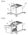
- FIG. 2A is a perspective view illustrating the whole of a transport device
- FIG. 2B is a perspective view illustrating a state where an accommodating unit is pulled out
- FIG. 3 is a vertical sectional view of the transport device
- FIG. 4 is a vertical sectional schematic diagram illustrating apart of the transport device including a moving mechanism
- FIG. 5A is a plan view of the transport device in a state where an accommodating unit is partially pulled out
- FIG. 5B is a plan view of the transport device in a state where the accommodating unit is mounted;
- FIG. 6A is a bottom view of the transport device in a state where the accommodating unit is partially pulled out
- FIG. 6B is a bottom view of the transport device in a state where the accommodating unit is mounted.
- FIGS. 7A to 7C are plan schematic diagrams illustrating the positioning of the accommodating unit with respect to a body unit.
- the front-rear direction is the X-axis direction
- the left-right direction is the Y-axis direction
- the up-down direction is the Z-axis direction.
- FIG. 1 is a schematic configuration diagram illustrating an image forming system 1 to which a transport device 200 according to the present exemplary embodiment is applied.
- the image forming system 1 illustrated in FIG. 1 includes an image forming apparatus 100 , such as a printer or a copier, which forms an image by an electrophotographic system, and the transport device 200 configured to transport a sheet P as a recording medium on which a toner image is formed, to the image forming apparatus 100 .
- an image forming apparatus 100 such as a printer or a copier, which forms an image by an electrophotographic system
- the transport device 200 configured to transport a sheet P as a recording medium on which a toner image is formed, to the image forming apparatus 100 .
- the image forming apparatus 100 is configured to include a controller 10 , a sheet feeding device 20 , photoconductor units 30 , developing devices 40 , a transfer device 50 , and a fixing device 60 .
- the transport device 200 is disposed below the image forming apparatus 100 ( ⁇ Z direction), and transports a sheet P, on which an image is to be recorded, to the image forming apparatus 100 .
- the sheet feeding device 20 on which sheets P as recording mediums are stacked is provided.
- Sheets P, of which the position in the width direction is determined on a regulation plate (not illustrated), are pulled out one by one from the top by a sheet pull-out unit 22 forward ( ⁇ X direction) and transported to a nip portion of a resist roller pair 23 .
- the photoconductor units 30 include photoconductor drums 31 which are provided, respectively, in parallel above the sheet feeding device 20 (Z direction), and are rotationally driven. On each of the photoconductor drums 31 , a toner image of yellow (Y), magenta (M), cyan (C), or black (K) is formed by each of the developing devices 40 .
- the toner images of respective colors formed, respectively, on the photoconductor drums 31 of the photoconductor units 30 are sequentially electrostatically transferred (primarily transferred) on an intermediate transfer belt 51 of the transfer device 50 , and a superimposed toner image obtained by superimposing the toners of respective colors is formed.
- the superimposed toner image on the intermediate transfer belt 51 is fed from the resist roller pair 23 and collectively transferred to a sheet P guided by a transport guide by a secondary transfer roller 52 .
- the sheet P on which the toner images are collectively transferred in the transfer device 50 is transported to the fixing device 60 in a state where the toner images are unfixed, and the toner images are fixed through an action of pressing and heating by a pair of heating and pressure modules 61 and 62 .
- the sheet P formed with the fixed toner images is guided by the transport guide, and discharged to and accommodated in an exit tray unit T formed on the top surface of the image forming apparatus 100 (Z direction) from a pair of exit rollers 69 .
- the transport device 200 includes a body unit 210 and an accommodating unit 220 .
- the body unit 210 is configured to be detachable with respect to the image forming apparatus 100 , and has a transport path of a sheet P to be connected to a sheet transport path included in the image forming apparatus 100 .
- the accommodating unit 220 is configured to accommodate a number of sheets P, and mounted to be reciprocal with respect to the body unit 210 .
- the accommodating unit 220 includes a sheet stacking plate BP on which sheets P are stacked, and moves the sheet stacking plate BP according to the remaining amount of the sheets P.
- the accommodating unit 220 is mounted by being moved in the direction of the arrow R 1 in FIG. 1 (hereinafter, also referred to as a “mounting direction”), and is detached by being moved in the direction of the arrow R 2 (hereinafter, also referred to as a “detaching direction”), that is, its mounted state is released.
- a sheet feeding unit 230 is provided in the body unit 210 , and a supply unit 240 is attached to the accommodating unit 220 .
- a feed roll 232 as a transport member of the sheet feeding unit 230 and a retard roll 241 as a separation member of the supply unit 240 are abutted on each other so as to separate sheets P which are fed from a nudger roll 231 one by one and transport the separated sheets P to the image forming apparatus 100 .
- FIG. 2A is a perspective view illustrating the whole of the transport device 200
- FIG. 2B is a perspective view illustrating a state where the accommodating unit is pulled out
- FIG. 3 is a vertical sectional view of the transport device 200
- FIG. 4 is a vertical sectional view illustrating a part of the transport device 200 including a moving mechanism 250
- FIG. 5A is a plan view of the transport device 200 in a state where the accommodating unit 220 is slightly pulled out
- FIG. 5B is a plan view of the transport device 200 in a state where the accommodating unit 220 is mounted
- FIG. 6A is a bottom view of the transport device 200 in a state where the accommodating unit 220 is slightly pulled out
- FIG. 6B is a bottom view of the transport device 200 in a state where the accommodating unit 220 is mounted
- FIGS. 7A to 7C are plan schematic diagrams illustrating positioning of the accommodating unit 220 with respect to the body unit 210 .
- the transport device 200 includes the body unit 210 and the accommodating unit 220 reciprocally held by the body unit 210 .
- the sheet feeding unit 230 (illustrated in FIG. 1 ) is provided within a metallic housing 213 (illustrated in FIG. 3 ) covered with synthetic resinous outer covers 211 and 212 .
- the accommodating unit 220 is a box-shape tray in its entirety which is entirely composed of a bottom plate 221 , side plates 222 and 223 , a front cover 224 and a back plate 225 which are made of a synthetic resin material (illustrated in FIG. 3 ), and is attached with the supply unit 240 (illustrated in FIG. 1 ).
- the accommodating unit 220 is supported to be reciprocal with respect to the body unit 210 by the moving mechanism 250 .
- the moving mechanism 250 is a rail mechanism composed of first rails 251 attached to the side plates 222 and 223 of the accommodating unit 220 , second rails 252 assembled to the body unit 210 to be slidable with respect to the first rails, and intermediate rails 253 disposed to be slidable with respect to the second rails 252 .
- the accommodating unit 220 is supported to be mounted or detached with respect to the body unit 210 .
- the second rail 252 has a first gap G 1 with an outer surface 213 Ba of a body side plate 213 B through a stud S with respect to the body side plate 213 B erected from a bottom surface 213 A of the housing 213 of the body unit 210 , and a second gap G 2 with an inner surface 213 Bb of the body side plate 213 B, and is movably held in the direction intersecting with (perpendicular to) the reciprocating direction of the accommodating unit 220 .
- the accommodating unit 220 includes a pair of guide members 260 configured to regulate a position in a width direction intersecting with (perpendicular to) the transport direction of the sheets P.
- the guide members 260 are provided to be movable in a direction intersecting with (perpendicular to) the transport direction of the sheets P according to the size of the sheets to be accommodated.
- a positioning projection 226 is formed on the back plate 225 of the accommodating unit 220 to project toward the body unit 210 , and a positioning hole 215 is provided in the body unit 210 .
- the positioning projection 226 and the positioning hole 215 are fitted to each other to constitute a first positioning portion when the accommodating unit 220 is mounted in the body unit 210 .
- a positioning pin 216 projecting upward (Z direction) from the bottom surface 213 A of the housing 213 is provided in the body unit 210 , and a positioning guide 228 is formed on the bottom plate 221 of the accommodating unit 220 .
- the positioning pin 216 and the positioning guide 228 are fitted to each other to constitute a second positioning portion when the accommodating unit 220 is mounted in the body unit 210 .
- the first positioning portion and the second positioning portion are provided to be spaced apart from each other at the front side and the rear side of the transport device 200 , on the extension on which one of the pair of guide members 260 serving as a reference of a width direction of the sheet transport is provided.
- a handle portion 224 a of the front cover 224 is operated to move the accommodating unit 220 from the body unit 210 in the direction of the arrow R 2 (see FIG. 1 ) such that a sheet bundle is stacked on the sheet stacking plate BP in a state where the sheet stacking plate BP is exposed.
- the handle portion 224 a of the front cover 224 is operated so that the accommodating unit 220 is moved in the direction of the arrow R 1 to be mounted in the body unit 210 .
- the accommodating unit 220 is a box-shape tray in its entirety which is entirely composed of the bottom plate 221 , the side plates 222 and 223 , the front cover 224 and the back plate 225 which are made of a synthetic resin material and is lighter as a whole as compared to one made of a metal. Meanwhile, according to the temperature condition of the use environment where the transport device 200 is provided, apart or the whole of the accommodating unit 220 may be more easily expanded or shrunk as compared to one made of a metal.
- the moving mechanism 250 that reciprocally supports the accommodating unit 220 between the body unit 210 and the accommodating unit 220 may be pressed by the side plates 222 and 223 of the thermally expanded accommodating unit 220 , and thus its operating force may be increased.
- the position of the accommodating unit 220 may be moved so that the position in the width direction intersecting with (perpendicular to) the transport direction of the stacked sheets P may be changed.
- the accommodating unit 220 is supported to be reciprocal with respect to the body unit 210 by a rail mechanism composed of the first rails 251 attached to the side plates 222 and 223 of the accommodating unit 220 , the second rails 252 assembled to the body unit 210 to be slidable with respect to the first rails, and the intermediate rails 253 disposed to be slidable with respect to the second rails 252 .
- the second rail 252 has the first gap G 1 with the outer surface 213 Ba of the body side plate 213 B through the stud S with respect to the body side plate 213 B of the body unit 210 , and the second gap G 2 with the inner surface 213 Bb of the body side plate 213 B.
- the accommodating unit 220 When the synthetic resinous accommodating unit 220 is thermally expanded, the accommodating unit 220 is moved by the thermal expansion.
- the second rail 252 and the intermediate rail 253 press the second rail 252 toward the body side plate 213 B of the body unit 210 through a ball BR (see the arrow F 1 in FIG. 4 ).
- the movement of the accommodating unit 220 by the thermal expansion is absorbed by the second gap G 2 provided between an outer surface 252 a of the pressed second rail 252 and the inner surface 213 Bb of the body side plate 213 B.
- the accommodating unit 220 When the synthetic resinous accommodating unit 220 is shrunk, the accommodating unit 220 is moved by the shrinkage.
- the second rail 252 and the intermediate rail 253 act to draw the second rail 252 from the body side plate 213 B of the body unit 210 to the inside through the ball BR (see the arrow F 2 in FIG. 4 ).
- the movement of the accommodating unit 220 by the shrinkage is absorbed by the first gap G 1 between the outer surface 213 Ba of the body side plate 213 B and the stud S.
- the accommodating unit 220 is thermally expanded or shrunk, the operating force when the accommodating unit 220 is mounted in or detached from the body unit 210 is suppressed from being increased.
- the first positioning portion and the second positioning portion are provided to be spaced apart from each other at the front side and the rear side of the transport device 200 , on the extension on which one of the pair of guide members 260 serving as a reference of a width direction of the sheet transport is provided.
- the accommodating unit 220 is expanded or shrunk, a position variation in one of the guide members 260 with respect to the body unit 210 is suppressed, and a position variation in the width direction of the transported sheet P is suppressed.
Landscapes
- Engineering & Computer Science (AREA)
- Mechanical Engineering (AREA)
- Physics & Mathematics (AREA)
- General Physics & Mathematics (AREA)
- Sheets, Magazines, And Separation Thereof (AREA)
- Electrophotography Configuration And Component (AREA)
- Chain Conveyers (AREA)
Abstract
Description
Claims (16)
Applications Claiming Priority (4)
| Application Number | Priority Date | Filing Date | Title |
|---|---|---|---|
| JP2016056546A JP6876225B2 (en) | 2016-03-22 | 2016-03-22 | Transport device |
| JP2016-056545 | 2016-03-22 | ||
| JP2016056545A JP2017171416A (en) | 2016-03-22 | 2016-03-22 | Transport device |
| JP2016-056546 | 2016-03-22 |
Publications (2)
| Publication Number | Publication Date |
|---|---|
| US20170277103A1 US20170277103A1 (en) | 2017-09-28 |
| US9836003B2 true US9836003B2 (en) | 2017-12-05 |
Family
ID=59896325
Family Applications (2)
| Application Number | Title | Priority Date | Filing Date |
|---|---|---|---|
| US15/207,579 Expired - Fee Related US9836003B2 (en) | 2016-03-22 | 2016-07-12 | Transport device |
| US15/225,922 Abandoned US20170275107A1 (en) | 2016-03-22 | 2016-08-02 | Transport device |
Family Applications After (1)
| Application Number | Title | Priority Date | Filing Date |
|---|---|---|---|
| US15/225,922 Abandoned US20170275107A1 (en) | 2016-03-22 | 2016-08-02 | Transport device |
Country Status (2)
| Country | Link |
|---|---|
| US (2) | US9836003B2 (en) |
| CN (2) | CN107215690B (en) |
Families Citing this family (1)
| Publication number | Priority date | Publication date | Assignee | Title |
|---|---|---|---|---|
| JP2025022084A (en) * | 2023-08-02 | 2025-02-14 | 京セラドキュメントソリューションズ株式会社 | SHEET FEEDING DEVICE AND IMAGE FORMING APPARATUS INCLUDING THE SAME |
Citations (16)
| Publication number | Priority date | Publication date | Assignee | Title |
|---|---|---|---|---|
| US4231566A (en) * | 1977-11-30 | 1980-11-04 | Ricoh Company, Ltd. | Sheet feed apparatus |
| US5135214A (en) * | 1990-07-20 | 1992-08-04 | Sharp Kabushiki Kaisha | Feeding device |
| US5149079A (en) * | 1989-05-15 | 1992-09-22 | Sharp Kabushiki Kaisha | Feeding device having a pivotal copy material holding plate |
| US5150890A (en) * | 1989-05-15 | 1992-09-29 | Sharp Kabushiki Kaisha | Feeding device for enabling continuous copy paper feed from plural copy paper cassettes |
| US5217217A (en) * | 1991-04-22 | 1993-06-08 | Sharp Kabushiki Kaisha | Paper feeding device for feeding paper in longitudinal and lateral directions |
| US20030075857A1 (en) * | 2001-10-19 | 2003-04-24 | Satoru Matsuki | Sheet feeding apparatus and image forming apparatus |
| US20070045946A1 (en) * | 2005-09-01 | 2007-03-01 | Sharp Kabushiki Kaisha | Sheet feeding device |
| US20090256303A1 (en) * | 2008-04-14 | 2009-10-15 | Yuichi Adachi | Sheet containing apparatus and image forming system |
| US20130062827A1 (en) * | 2011-09-08 | 2013-03-14 | Ricoh Company, Limited | Sheet feeder and image forming system |
| US20130334766A1 (en) * | 2012-06-13 | 2013-12-19 | Ricoh Company, Ltd. | Slide rail, sheet feed device, and image forming apparatus |
| US20140021680A1 (en) * | 2012-07-18 | 2014-01-23 | Canon Kabushiki Kaisha | Sheet feeding apparatus and image forming apparatus |
| US20140055016A1 (en) * | 2012-08-22 | 2014-02-27 | Ricoh Company, Ltd. | Image forming apparatus |
| US20140203496A1 (en) * | 2013-01-18 | 2014-07-24 | Canon Kabushiki Kaisha | Sheet feeding device and image forming apparatus |
| US20140217669A1 (en) * | 2011-07-26 | 2014-08-07 | Hitachi-Omron Terminal Solutions, Corp. | Paper sheet processing device |
| US20150115523A1 (en) * | 2013-10-30 | 2015-04-30 | Kyocera Document Solutions Inc. | Sheet stacking device, sheet conveying device, and image forming apparatus |
| US20150284195A1 (en) | 2014-04-04 | 2015-10-08 | Canon Kabushiki Kaisha | Sheet feeding apparatus and image forming apparatus |
Family Cites Families (11)
| Publication number | Priority date | Publication date | Assignee | Title |
|---|---|---|---|---|
| JPS6023231A (en) * | 1983-07-15 | 1985-02-05 | Canon Inc | feeding device |
| JPH05292241A (en) * | 1992-04-15 | 1993-11-05 | Konica Corp | Flat color scanner for printing |
| JPH06227689A (en) * | 1993-01-28 | 1994-08-16 | Murata Mach Ltd | Paper sheet supply device |
| KR100209506B1 (en) * | 1996-10-28 | 1999-07-15 | 윤종용 | In the office automation equipment, |
| JP4150347B2 (en) * | 2003-03-31 | 2008-09-17 | 株式会社リコー | Paper feeding device and image forming apparatus |
| US7210677B2 (en) * | 2003-07-04 | 2007-05-01 | Murata Kikai Kabushiki Kaisha | Paper feeder and image scanning device |
| JP4777201B2 (en) * | 2006-09-20 | 2011-09-21 | 京セラミタ株式会社 | Paper feeder |
| JP2008285264A (en) * | 2007-05-16 | 2008-11-27 | Canon Inc | Image forming apparatus |
| JP5585875B2 (en) * | 2010-09-14 | 2014-09-10 | 株式会社リコー | Feeding apparatus and image forming apparatus |
| JP5891581B2 (en) * | 2011-01-18 | 2016-03-23 | 富士ゼロックス株式会社 | Recording medium supply device and image forming apparatus |
| JP5836318B2 (en) * | 2013-05-29 | 2015-12-24 | 京セラドキュメントソリューションズ株式会社 | Paper feeding device, and image forming apparatus and image reading apparatus provided with the same |
-
2016
- 2016-07-12 US US15/207,579 patent/US9836003B2/en not_active Expired - Fee Related
- 2016-08-02 US US15/225,922 patent/US20170275107A1/en not_active Abandoned
- 2016-09-09 CN CN201610812479.8A patent/CN107215690B/en active Active
- 2016-09-09 CN CN201610815550.8A patent/CN107215687A/en active Pending
Patent Citations (17)
| Publication number | Priority date | Publication date | Assignee | Title |
|---|---|---|---|---|
| US4231566A (en) * | 1977-11-30 | 1980-11-04 | Ricoh Company, Ltd. | Sheet feed apparatus |
| US5149079A (en) * | 1989-05-15 | 1992-09-22 | Sharp Kabushiki Kaisha | Feeding device having a pivotal copy material holding plate |
| US5150890A (en) * | 1989-05-15 | 1992-09-29 | Sharp Kabushiki Kaisha | Feeding device for enabling continuous copy paper feed from plural copy paper cassettes |
| US5135214A (en) * | 1990-07-20 | 1992-08-04 | Sharp Kabushiki Kaisha | Feeding device |
| US5217217A (en) * | 1991-04-22 | 1993-06-08 | Sharp Kabushiki Kaisha | Paper feeding device for feeding paper in longitudinal and lateral directions |
| US20030075857A1 (en) * | 2001-10-19 | 2003-04-24 | Satoru Matsuki | Sheet feeding apparatus and image forming apparatus |
| US20070045946A1 (en) * | 2005-09-01 | 2007-03-01 | Sharp Kabushiki Kaisha | Sheet feeding device |
| US20090256303A1 (en) * | 2008-04-14 | 2009-10-15 | Yuichi Adachi | Sheet containing apparatus and image forming system |
| US20140217669A1 (en) * | 2011-07-26 | 2014-08-07 | Hitachi-Omron Terminal Solutions, Corp. | Paper sheet processing device |
| US20130062827A1 (en) * | 2011-09-08 | 2013-03-14 | Ricoh Company, Limited | Sheet feeder and image forming system |
| US20130334766A1 (en) * | 2012-06-13 | 2013-12-19 | Ricoh Company, Ltd. | Slide rail, sheet feed device, and image forming apparatus |
| US20140021680A1 (en) * | 2012-07-18 | 2014-01-23 | Canon Kabushiki Kaisha | Sheet feeding apparatus and image forming apparatus |
| US20140055016A1 (en) * | 2012-08-22 | 2014-02-27 | Ricoh Company, Ltd. | Image forming apparatus |
| US20140203496A1 (en) * | 2013-01-18 | 2014-07-24 | Canon Kabushiki Kaisha | Sheet feeding device and image forming apparatus |
| US20150115523A1 (en) * | 2013-10-30 | 2015-04-30 | Kyocera Document Solutions Inc. | Sheet stacking device, sheet conveying device, and image forming apparatus |
| US20150284195A1 (en) | 2014-04-04 | 2015-10-08 | Canon Kabushiki Kaisha | Sheet feeding apparatus and image forming apparatus |
| JP2015199556A (en) | 2014-04-04 | 2015-11-12 | キヤノン株式会社 | Sheet feeding apparatus and image forming apparatus |
Also Published As
| Publication number | Publication date |
|---|---|
| CN107215690B (en) | 2019-03-08 |
| CN107215687A (en) | 2017-09-29 |
| US20170275107A1 (en) | 2017-09-28 |
| CN107215690A (en) | 2017-09-29 |
| US20170277103A1 (en) | 2017-09-28 |
Similar Documents
| Publication | Publication Date | Title |
|---|---|---|
| CN101770193A (en) | Image forming apparatus and developing cartridge | |
| US9242823B2 (en) | Sheet detecting apparatus, sheet conveying apparatus, and image forming apparatus | |
| US10061265B2 (en) | Image forming apparatus including a fixing unit which fixes a toner image on a recording medium | |
| US20150346682A1 (en) | Image forming apparatus | |
| US9494918B2 (en) | Image forming apparatus | |
| US20120207522A1 (en) | Image forming apparatus | |
| US8774674B2 (en) | Image forming apparatus and transport guiding device having a smoothly operating door | |
| US9944478B2 (en) | Sheet supporting apparatus and image forming apparatus | |
| US9085431B2 (en) | Sheet feed cassette | |
| US9836003B2 (en) | Transport device | |
| US20150098735A1 (en) | Fixing device, and image forming apparatus | |
| US9037041B2 (en) | Image forming apparatus and transfer device having a rotatable door | |
| US10180651B2 (en) | Image forming apparatus with restricting member that restricts movement of cartridge | |
| US10935910B2 (en) | Image forming apparatus in which corrugated shape is formed in width direction on sheet to which air is blown | |
| US9323174B2 (en) | Image forming apparatus | |
| US9790040B2 (en) | Sheet feeding device and image forming apparatus including the same | |
| US11614709B1 (en) | Accommodating device and image forming apparatus | |
| US10216121B2 (en) | Transfer unit and image forming apparatus | |
| JP6876225B2 (en) | Transport device | |
| JP6103973B2 (en) | Sheet feeding apparatus and image forming apparatus | |
| US9746822B2 (en) | Image forming apparatus | |
| US20170052497A1 (en) | Recording-medium supplying device and image forming apparatus | |
| JP2012037914A (en) | Image forming apparatus | |
| JP4526118B2 (en) | Image forming apparatus | |
| US10046928B2 (en) | Transport apparatus |
Legal Events
| Date | Code | Title | Description |
|---|---|---|---|
| AS | Assignment |
Owner name: FUJI XEROX CO., LTD., JAPAN Free format text: ASSIGNMENT OF ASSIGNORS INTEREST;ASSIGNORS:MAEDA, SHOUICHI;ABE, TAKASHI;YAZAWA, TAKAYUKI;AND OTHERS;REEL/FRAME:039130/0947 Effective date: 20160701 |
|
| STCF | Information on status: patent grant |
Free format text: PATENTED CASE |
|
| MAFP | Maintenance fee payment |
Free format text: PAYMENT OF MAINTENANCE FEE, 4TH YEAR, LARGE ENTITY (ORIGINAL EVENT CODE: M1551); ENTITY STATUS OF PATENT OWNER: LARGE ENTITY Year of fee payment: 4 |
|
| AS | Assignment |
Owner name: FUJIFILM BUSINESS INNOVATION CORP., JAPAN Free format text: CHANGE OF NAME;ASSIGNOR:FUJI XEROX CO., LTD.;REEL/FRAME:058287/0056 Effective date: 20210401 |
|
| FEPP | Fee payment procedure |
Free format text: MAINTENANCE FEE REMINDER MAILED (ORIGINAL EVENT CODE: REM.); ENTITY STATUS OF PATENT OWNER: LARGE ENTITY |
|
| LAPS | Lapse for failure to pay maintenance fees |
Free format text: PATENT EXPIRED FOR FAILURE TO PAY MAINTENANCE FEES (ORIGINAL EVENT CODE: EXP.); ENTITY STATUS OF PATENT OWNER: LARGE ENTITY |
|
| STCH | Information on status: patent discontinuation |
Free format text: PATENT EXPIRED DUE TO NONPAYMENT OF MAINTENANCE FEES UNDER 37 CFR 1.362 |
|
| FP | Lapsed due to failure to pay maintenance fee |
Effective date: 20251205 |