US9835448B2 - Hologram for alignment - Google Patents
Hologram for alignment Download PDFInfo
- Publication number
- US9835448B2 US9835448B2 US15/037,456 US201315037456A US9835448B2 US 9835448 B2 US9835448 B2 US 9835448B2 US 201315037456 A US201315037456 A US 201315037456A US 9835448 B2 US9835448 B2 US 9835448B2
- Authority
- US
- United States
- Prior art keywords
- target
- holographic
- view
- encoded
- hologram device
- Prior art date
- Legal status (The legal status is an assumption and is not a legal conclusion. Google has not performed a legal analysis and makes no representation as to the accuracy of the status listed.)
- Expired - Fee Related, expires
Links
Images


Classifications
-
- G—PHYSICS
- G01—MEASURING; TESTING
- G01B—MEASURING LENGTH, THICKNESS OR SIMILAR LINEAR DIMENSIONS; MEASURING ANGLES; MEASURING AREAS; MEASURING IRREGULARITIES OF SURFACES OR CONTOURS
- G01B11/00—Measuring arrangements characterised by the use of optical techniques
- G01B11/26—Measuring arrangements characterised by the use of optical techniques for measuring angles or tapers; for testing the alignment of axes
- G01B11/27—Measuring arrangements characterised by the use of optical techniques for measuring angles or tapers; for testing the alignment of axes for testing the alignment of axes
- G01B11/272—Measuring arrangements characterised by the use of optical techniques for measuring angles or tapers; for testing the alignment of axes for testing the alignment of axes using photoelectric detection means
-
- G—PHYSICS
- G03—PHOTOGRAPHY; CINEMATOGRAPHY; ANALOGOUS TECHNIQUES USING WAVES OTHER THAN OPTICAL WAVES; ELECTROGRAPHY; HOLOGRAPHY
- G03H—HOLOGRAPHIC PROCESSES OR APPARATUS
- G03H1/00—Holographic processes or apparatus using light, infrared or ultraviolet waves for obtaining holograms or for obtaining an image from them; Details peculiar thereto
- G03H1/22—Processes or apparatus for obtaining an optical image from holograms
- G03H1/2249—Holobject properties
-
- G—PHYSICS
- G03—PHOTOGRAPHY; CINEMATOGRAPHY; ANALOGOUS TECHNIQUES USING WAVES OTHER THAN OPTICAL WAVES; ELECTROGRAPHY; HOLOGRAPHY
- G03H—HOLOGRAPHIC PROCESSES OR APPARATUS
- G03H1/00—Holographic processes or apparatus using light, infrared or ultraviolet waves for obtaining holograms or for obtaining an image from them; Details peculiar thereto
- G03H1/26—Processes or apparatus specially adapted to produce multiple sub- holograms or to obtain images from them, e.g. multicolour technique
- G03H1/2645—Multiplexing processes, e.g. aperture, shift, or wavefront multiplexing
- G03H1/265—Angle multiplexing; Multichannel holograms
-
- G—PHYSICS
- G06—COMPUTING OR CALCULATING; COUNTING
- G06K—GRAPHICAL DATA READING; PRESENTATION OF DATA; RECORD CARRIERS; HANDLING RECORD CARRIERS
- G06K19/00—Record carriers for use with machines and with at least a part designed to carry digital markings
- G06K19/06—Record carriers for use with machines and with at least a part designed to carry digital markings characterised by the kind of the digital marking, e.g. shape, nature, code
- G06K19/06009—Record carriers for use with machines and with at least a part designed to carry digital markings characterised by the kind of the digital marking, e.g. shape, nature, code with optically detectable marking
- G06K19/06037—Record carriers for use with machines and with at least a part designed to carry digital markings characterised by the kind of the digital marking, e.g. shape, nature, code with optically detectable marking multi-dimensional coding
-
- G—PHYSICS
- G06—COMPUTING OR CALCULATING; COUNTING
- G06K—GRAPHICAL DATA READING; PRESENTATION OF DATA; RECORD CARRIERS; HANDLING RECORD CARRIERS
- G06K7/00—Methods or arrangements for sensing record carriers, e.g. for reading patterns
- G06K7/10—Methods or arrangements for sensing record carriers, e.g. for reading patterns by electromagnetic radiation, e.g. optical sensing; by corpuscular radiation
- G06K7/10544—Methods or arrangements for sensing record carriers, e.g. for reading patterns by electromagnetic radiation, e.g. optical sensing; by corpuscular radiation by scanning of the records by radiation in the optical part of the electromagnetic spectrum
- G06K7/10554—Moving beam scanning
- G06K7/10594—Beam path
- G06K7/10603—Basic scanning using moving elements
- G06K7/10663—Basic scanning using moving elements using hologram
-
- G—PHYSICS
- G06—COMPUTING OR CALCULATING; COUNTING
- G06K—GRAPHICAL DATA READING; PRESENTATION OF DATA; RECORD CARRIERS; HANDLING RECORD CARRIERS
- G06K7/00—Methods or arrangements for sensing record carriers, e.g. for reading patterns
- G06K7/10—Methods or arrangements for sensing record carriers, e.g. for reading patterns by electromagnetic radiation, e.g. optical sensing; by corpuscular radiation
- G06K7/10544—Methods or arrangements for sensing record carriers, e.g. for reading patterns by electromagnetic radiation, e.g. optical sensing; by corpuscular radiation by scanning of the records by radiation in the optical part of the electromagnetic spectrum
- G06K7/10712—Fixed beam scanning
- G06K7/10722—Photodetector array or CCD scanning
- G06K7/10732—Light sources
-
- G—PHYSICS
- G06—COMPUTING OR CALCULATING; COUNTING
- G06K—GRAPHICAL DATA READING; PRESENTATION OF DATA; RECORD CARRIERS; HANDLING RECORD CARRIERS
- G06K7/00—Methods or arrangements for sensing record carriers, e.g. for reading patterns
- G06K7/10—Methods or arrangements for sensing record carriers, e.g. for reading patterns by electromagnetic radiation, e.g. optical sensing; by corpuscular radiation
- G06K7/14—Methods or arrangements for sensing record carriers, e.g. for reading patterns by electromagnetic radiation, e.g. optical sensing; by corpuscular radiation using light without selection of wavelength, e.g. sensing reflected white light
- G06K7/1404—Methods for optical code recognition
- G06K7/1408—Methods for optical code recognition the method being specifically adapted for the type of code
- G06K7/1417—2D bar codes
-
- G—PHYSICS
- G03—PHOTOGRAPHY; CINEMATOGRAPHY; ANALOGOUS TECHNIQUES USING WAVES OTHER THAN OPTICAL WAVES; ELECTROGRAPHY; HOLOGRAPHY
- G03H—HOLOGRAPHIC PROCESSES OR APPARATUS
- G03H1/00—Holographic processes or apparatus using light, infrared or ultraviolet waves for obtaining holograms or for obtaining an image from them; Details peculiar thereto
- G03H1/22—Processes or apparatus for obtaining an optical image from holograms
- G03H1/2249—Holobject properties
- G03H2001/2273—Pseudo-dynamic holobject, e.g. due to angle multiplexing and viewer motion
-
- G—PHYSICS
- G03—PHOTOGRAPHY; CINEMATOGRAPHY; ANALOGOUS TECHNIQUES USING WAVES OTHER THAN OPTICAL WAVES; ELECTROGRAPHY; HOLOGRAPHY
- G03H—HOLOGRAPHIC PROCESSES OR APPARATUS
- G03H2210/00—Object characteristics
- G03H2210/30—3D object
-
- G—PHYSICS
- G03—PHOTOGRAPHY; CINEMATOGRAPHY; ANALOGOUS TECHNIQUES USING WAVES OTHER THAN OPTICAL WAVES; ELECTROGRAPHY; HOLOGRAPHY
- G03H—HOLOGRAPHIC PROCESSES OR APPARATUS
- G03H2210/00—Object characteristics
- G03H2210/50—Nature of the object
- G03H2210/53—Coded object not directly interpretable, e.g. encrypted object, barcode
-
- H—ELECTRICITY
- H04—ELECTRIC COMMUNICATION TECHNIQUE
- H04M—TELEPHONIC COMMUNICATION
- H04M2250/00—Details of telephonic subscriber devices
- H04M2250/52—Details of telephonic subscriber devices including functional features of a camera
Definitions
- Alignment of objects may be required in many situations. For example, in taking photos for passports, an individual's head must be positioned properly relative to the camera. Further, in many robotic manufacturing or processing applications, for example, an object may be needed to be aligned with respect to another object or to a machine with a specific orientation, such as may be required in the case of a robot moving within an automated warehouse.
- FIG. 1 illustrates a camera device with an example hologram device
- FIG. 2 illustrates a camera device with another example hologram device
- FIG. 3 illustrates an example of a user with a camera having an example hologram device
- FIG. 4 illustrates an example of a user using a camera system with an example hologram device
- FIG. 5 illustrates a system with an object having an example hologram device for alignment with a camera
- FIG. 6 provides a schematic illustration of an example position identification system
- FIG. 7 illustrates an example hologram device viewed from various positions
- FIG. 8 illustrates various views of an example three-dimensional object for encoding on a holographic device
- FIGS. 9A-9D illustrate example holographic images for encoding on hologram devices.
- a hologram device is used to facilitate alignment.
- the hologram device may include an encoded holographic image which may have different views when viewed from various positions. Each view of the encoded image may be indicative of a position relative to alignment with a target position. The target position may be associated with a target holographic view on the encoded holographic image of the hologram device.
- a hologram device may include conventional holograms.
- the hologram device may include a multi-view, three-dimensional display.
- the multi-view, three-dimensional display may be formed may reproduce light rays reflecting off an object from various angles to get a different image from different perspectives, such as the different eyes of a human viewer or an imaging device positioned at different positions relative to the hologram device.
- the multi-view, three-dimensional display may use non-patterned grooves to send light off in different directions.
- FIG. 1 illustrates a camera device with an example hologram device.
- the illustrated camera device 100 may be mobile phone or a digital camera.
- the camera device 100 includes a camera 110 , such as a front-facing camera on smartphone.
- the camera device 100 also includes a display 120 which provides the image seen through the camera 110 .
- the camera device 100 is provided with a hologram device 130 in the vicinity of the camera 110 .
- the hologram device 130 provides the user with an alignment mechanism to allow the user to look closer to the camera 110 .
- FIGS. 6-9 Various examples of the hologram device 130 are described below with reference to FIGS. 6-9 .
- FIG. 2 illustrates a camera device with another example hologram device.
- the camera device 200 of FIG. 2 is similar to the camera device 100 of FIG. 1 and includes a camera 210 , a display 220 and a hologram device 230 .
- the hologram device 230 is formed with an annular configuration and is positioned around the camera device 210 .
- the user may be allowed to look into the camera or close to the camera, rather than at the display screen.
- the hologram device may provide the user with an indication of proper alignment with the camera. Examples of the hologram device are described in greater detail below. Thus, the user is able to take a more desirable self-portrait.
- FIG. 3 illustrates an example of a system 300 including a user with a camera 310 having an example hologram device 320 .
- the hologram device 320 is a flat device which may be, but does not need to be, positioned parallel to the lens
- FIG. 3 illustrates the hologram device 320 schematically for purposes of clarity.
- the hologram device 320 allows the user to properly align the camera to photograph himself without the use of a display.
- the user may move the camera to achieve proper alignment using the hologram device 320 .
- the camera is pointed at the eyes of the user with the user looking into the lens of the camera.
- the user's head may be properly framed and rotationally aligned as well.
- a hologram device 420 may be used to properly position the user relative to a camera 410 .
- the user may move and use the hologram device to properly position himself.
- the user may be required to position himself in a particular manner relative to the camera or image capture device.
- a camera 510 may use a hologram device 520 on an object 530 to properly align the object.
- the camera 510 may be associated with a robotic processor which requires the object 530 to be in a particular position and/or orientation for processing.
- the hologram 520 may indicate the current position of the object 530 .
- a mechanism (not shown) may be provided to change the alignment or orientation of the object 530 based on the viewing of the hologram device 520 by the camera 510 .
- the cameral 510 may be mounted on a vehicle, and the hologram device 520 may be used to facilitate automated parking of the vehicle in, for example, a self-driving mode.
- the vehicle may be a robot-driven vehicle.
- FIG. 6 provides a schematic illustration of an example position identification system.
- a hologram device 610 is used for alignment of a visual device, such as a camera 620 .
- the visual device may be a human eye or any other imaging device.
- the line of sight between the camera 620 and a target point is shown as reference numeral 630
- reference numeral 632 represents the projection of the line of sight onto the hologram device 610 .
- the position of the camera 620 relative to the target can be represented as two angular measurements.
- the first angle 650 is the azimuth, measured as the angle between a reference direction in the plane of the hologram device, such as the reference line 612 , and the projection of the line of sight onto the hologram device 632 .
- the second angle 660 is the elevation from the plane of the hologram device 610 and the line of sight 630 .
- the position may be represented in a variety of other manners which are considered within the scope of the present disclosure.
- FIG. 7 illustrates an example hologram device viewed from various positions.
- the example hologram device 700 may include an encoded image of a matrix of dots.
- the example hologram device 700 may also include features 702 for facilitating orientation, or detecting the orientation, of the hologram device.
- different views of the encoded image may be indicative of the viewer's position relative to a target.
- the target may be the normal line-of-sight from the flat hologram device 700 extending through the center of the hologram device 700 .
- FIG. 7 shows a progression of views of the hologram device 700 illustrating how angular information can be transmitted optically to a viewer or an imaging device such as a camera.
- a target dot in the matrix of dots may appear differently from the other dots.
- the target dot may appear brighter, darker, or a different color, for example. The change in appearance may facilitate identification of the target position.
- the hologram device 700 may appear as illustrated in FIG. 7( b ) .
- FIG. 7( c ) illustrates the hologram device 700 as it may appear when viewed with the line of sight 20 degrees from normal in one dimension and 20 degrees from normal in the second direction.
- FIG. 7( d ) illustrates the hologram device 700 as it may appear when viewed from an angle of five degrees from the normal in one dimension. In this regard, two adjacent dots may appear as different from the other dots in the matrix.
- the hologram device may be encoded with an image of a three-dimensional object.
- Such an object may allow visual alignment through viewing of an orientation of the three-dimensional object.
- the orientation of the object may allow determination of the change in position needed for proper alignment.
- the three-dimensional object may include an asymmetric feature which may facilitate rotational alignment.
- FIG. 8 One example of a three-dimensional object having an asymmetric feature is illustrated in FIG. 8 , which includes various views of the example three-dimensional object.
- An image of the three-dimensional object, equivalent to a set of two-dimensional images, may be encoded as a hologram on a hologram device.
- the example object of FIG. 8 is a vase 800 having a body 810 , a handle 820 and an opening 830 .
- the target alignment of the vase may be with the user looking into the opening 830 toward the bottom of the inside of the vase 800 .
- the vase 800 may be viewed from an off-center perspective, as illustrated in FIGS. 8( a ) and 8( b ) .
- FIG. 8( c ) when properly aligned, the opening 830 of the vase 800 may change in appearance. For example, in FIG. 8( c ) , the opening is made darker. In other examples, the opening may be brighter, a different color or otherwise change visually.
- the three-dimensional object may include an asymmetric feature to allow proper rotational alignment.
- the handle 820 of the vase 800 provides the asymmetric feature. Proper rotational alignment is achieved when the handle 820 appears in a particular position, such as on the top side of the vase, as illustrated in FIG. 8( c ) .
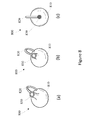
- FIGS. 9A-9D illustrate example holographic images for encoding on hologram devices.
- the encoded image may be sphere formed of facets, similar to a mirror ball.
- Each facet may include an indication of a position of the facet, for example, relative to a target facet.
- a view of the encoded image may correspond to one or more facets of the spherical encoded image.
- the position of each facet may be indicated in different manners.
- FIGS. 9A-9D illustrate some such examples.
- each view of the encoded image may include a view of a three-dimensional object, such as the object described above with reference to FIG. 8 .
- each facet of the spherical object may include an image of the three-dimensional object from a different perspective.
- Each different perspective may be indicative of the position of the corresponding view or facet relative to a target view or perspective.
- each view of the encoded image may include numerical values indicative of the angular position of the view relative to a target view.
- the values may be indicative of an azimuth value and an elevation angle, such as the angles described above with reference to FIG. 6 .
- a user or a camera viewing each view may learn the position change required to align with a target view or facet.
- each view of the encoded image may include a code indicative of the position of each view relative to a target view.
- the code may be a numerical value.
- the numerical values may be associated with a relative position through a table look-up, for example.
- each view or facet may include another machine-readable code, such as a bar code, a quick-read (QR) code or a 2-dimensional bar code.
- an imaging device may be coupled to a processor. The imaging device may capture the machine-readable code, and the processor may determine the change in position required for alignment with a target view or facet. The processor may cause a change in the position based on the relative position indicated by the machine-readable code.
- each view of the encoded image may include a graphical image indicating a target view or a direction to the target view.
- a target view or facet may be indicated by a target symbol
- non-target views or facets may be indicated by an arrow indicating the direction to the target.
- a feature of the arrow may indicate the magnitude of change required for alignment with the target.
- a length, thickness or brightness of the arrow may indicate a distance to the target view.
Landscapes
- Physics & Mathematics (AREA)
- General Physics & Mathematics (AREA)
- Engineering & Computer Science (AREA)
- Electromagnetism (AREA)
- Theoretical Computer Science (AREA)
- Health & Medical Sciences (AREA)
- General Health & Medical Sciences (AREA)
- Toxicology (AREA)
- Artificial Intelligence (AREA)
- Computer Vision & Pattern Recognition (AREA)
- Holo Graphy (AREA)
Applications Claiming Priority (1)
| Application Number | Priority Date | Filing Date | Title |
|---|---|---|---|
| PCT/US2013/072480 WO2015080750A1 (en) | 2013-11-29 | 2013-11-29 | Hologram for alignment |
Publications (2)
| Publication Number | Publication Date |
|---|---|
| US20160305775A1 US20160305775A1 (en) | 2016-10-20 |
| US9835448B2 true US9835448B2 (en) | 2017-12-05 |
Family
ID=53199524
Family Applications (1)
| Application Number | Title | Priority Date | Filing Date |
|---|---|---|---|
| US15/037,456 Expired - Fee Related US9835448B2 (en) | 2013-11-29 | 2013-11-29 | Hologram for alignment |
Country Status (4)
| Country | Link |
|---|---|
| US (1) | US9835448B2 (de) |
| EP (1) | EP3074823B1 (de) |
| CN (1) | CN105723285B (de) |
| WO (1) | WO2015080750A1 (de) |
Cited By (1)
| Publication number | Priority date | Publication date | Assignee | Title |
|---|---|---|---|---|
| US11036048B2 (en) * | 2018-10-03 | 2021-06-15 | Project Whitecard Digital Inc. | Virtual reality system and method for displaying on a real-world display a viewable portion of a source file projected on an inverse spherical virtual screen |
Families Citing this family (6)
| Publication number | Priority date | Publication date | Assignee | Title |
|---|---|---|---|---|
| CN106842882B (zh) * | 2017-04-02 | 2022-03-18 | 浙江工业大学 | 一种自身可见的全息显示装置 |
| US12006143B2 (en) | 2017-11-14 | 2024-06-11 | Hai Robotics Co., Ltd. | Handling robot |
| US12330870B2 (en) | 2017-11-14 | 2025-06-17 | Hai Robotics Co., Ltd. | Handling robot |
| CA3084526C (en) | 2017-11-14 | 2024-02-20 | Hai Robotics Co., Ltd. | Handling robot and method for retrieving inventory item based on handling robot |
| US12103771B2 (en) | 2017-11-14 | 2024-10-01 | Hai Robotics Co., Ltd. | Handling robot |
| US11465840B2 (en) | 2017-11-14 | 2022-10-11 | Hai Robotics Co., Ltd. | Handling robot |
Citations (12)
| Publication number | Priority date | Publication date | Assignee | Title |
|---|---|---|---|---|
| US4576458A (en) | 1983-04-05 | 1986-03-18 | Fuji Photo Film Co., Ltd. | Camera finder employing holographic view field frames |
| WO2002002351A1 (en) | 2000-07-03 | 2002-01-10 | Optaglio Limited | Optical device |
| US6559948B1 (en) | 1999-06-30 | 2003-05-06 | Raytheon Company | Method for locating a structure using holograms |
| JP2003339657A (ja) | 2002-05-24 | 2003-12-02 | Kanazawa Inst Of Technology | 3次元ベクトルの2次元表示方法および装置 |
| US20050190680A1 (en) | 2001-10-06 | 2005-09-01 | Samsung Electronics Co., Ltd. | Method of aligning optical system using a hologram and apparatus therefor |
| JP2008197574A (ja) | 2007-02-15 | 2008-08-28 | Funai Electric Co Ltd | ホログラム装置およびホログラム記録装置 |
| US7511805B2 (en) | 2005-11-28 | 2009-03-31 | Leica Geosystems Ag | Holographic test plate for positioning and aligning pipes |
| US20090257104A1 (en) | 2005-12-13 | 2009-10-15 | Adrian James Cable | Hologram Viewing Arrangement and Alignment Device |
| US20100045701A1 (en) | 2008-08-22 | 2010-02-25 | Cybernet Systems Corporation | Automatic mapping of augmented reality fiducials |
| US20100208057A1 (en) | 2009-02-13 | 2010-08-19 | Peter Meier | Methods and systems for determining the pose of a camera with respect to at least one object of a real environment |
| US20110001928A1 (en) | 2009-05-01 | 2011-01-06 | Sunita Sayeram | Systems for Imaging Structures of a Subject and Related Methods |
| US20130022222A1 (en) * | 2010-04-01 | 2013-01-24 | Seereal Technologies S.A. | Method and device for encoding three-dimensional scenes which include transparent objects in a holographic system |
Family Cites Families (1)
| Publication number | Priority date | Publication date | Assignee | Title |
|---|---|---|---|---|
| JP5521040B2 (ja) * | 2009-07-09 | 2014-06-11 | ビルケア テクノロジーズ シンガポール プライベート リミテッド | 識別されるように構成されたタグまたは物体を識別可能な読み取り装置、関連の方法、およびシステム |
-
2013
- 2013-11-29 EP EP13898132.9A patent/EP3074823B1/de active Active
- 2013-11-29 WO PCT/US2013/072480 patent/WO2015080750A1/en not_active Ceased
- 2013-11-29 US US15/037,456 patent/US9835448B2/en not_active Expired - Fee Related
- 2013-11-29 CN CN201380080953.7A patent/CN105723285B/zh not_active Expired - Fee Related
Patent Citations (12)
| Publication number | Priority date | Publication date | Assignee | Title |
|---|---|---|---|---|
| US4576458A (en) | 1983-04-05 | 1986-03-18 | Fuji Photo Film Co., Ltd. | Camera finder employing holographic view field frames |
| US6559948B1 (en) | 1999-06-30 | 2003-05-06 | Raytheon Company | Method for locating a structure using holograms |
| WO2002002351A1 (en) | 2000-07-03 | 2002-01-10 | Optaglio Limited | Optical device |
| US20050190680A1 (en) | 2001-10-06 | 2005-09-01 | Samsung Electronics Co., Ltd. | Method of aligning optical system using a hologram and apparatus therefor |
| JP2003339657A (ja) | 2002-05-24 | 2003-12-02 | Kanazawa Inst Of Technology | 3次元ベクトルの2次元表示方法および装置 |
| US7511805B2 (en) | 2005-11-28 | 2009-03-31 | Leica Geosystems Ag | Holographic test plate for positioning and aligning pipes |
| US20090257104A1 (en) | 2005-12-13 | 2009-10-15 | Adrian James Cable | Hologram Viewing Arrangement and Alignment Device |
| JP2008197574A (ja) | 2007-02-15 | 2008-08-28 | Funai Electric Co Ltd | ホログラム装置およびホログラム記録装置 |
| US20100045701A1 (en) | 2008-08-22 | 2010-02-25 | Cybernet Systems Corporation | Automatic mapping of augmented reality fiducials |
| US20100208057A1 (en) | 2009-02-13 | 2010-08-19 | Peter Meier | Methods and systems for determining the pose of a camera with respect to at least one object of a real environment |
| US20110001928A1 (en) | 2009-05-01 | 2011-01-06 | Sunita Sayeram | Systems for Imaging Structures of a Subject and Related Methods |
| US20130022222A1 (en) * | 2010-04-01 | 2013-01-24 | Seereal Technologies S.A. | Method and device for encoding three-dimensional scenes which include transparent objects in a holographic system |
Non-Patent Citations (3)
| Title |
|---|
| Almeida, C.S.D.B. et al., A Proposal of a Multi-view Environment for Markerless Augmented Reality [online], Jun. 29, 2013, Retrieved from the Internet <http://www.ucsp.edu.pe/sibgrapi2013/eproceedings/wip/115208.pdf>, [retrieved on Sep. 24, 2013], 4 pages. |
| Jiang, B. et al., Camera Tracking for Augmented Reality Media [online], Apr. 17, 2000, Retrieved from the Internet <http://graphics.usc.edu/cgit/publications/papers/Bolanp280.pdf> [retrieved on Sep. 24, 2013], 4 pages. |
| Kozacki, T. et al., Holographic Capture and Display Systems in Circular Configurations, Journal of Display Technology, Apr. 2012, vol. 8, No. 4, pp. 225-232. |
Cited By (1)
| Publication number | Priority date | Publication date | Assignee | Title |
|---|---|---|---|---|
| US11036048B2 (en) * | 2018-10-03 | 2021-06-15 | Project Whitecard Digital Inc. | Virtual reality system and method for displaying on a real-world display a viewable portion of a source file projected on an inverse spherical virtual screen |
Also Published As
| Publication number | Publication date |
|---|---|
| EP3074823A4 (de) | 2017-06-21 |
| EP3074823B1 (de) | 2020-11-04 |
| CN105723285A (zh) | 2016-06-29 |
| WO2015080750A1 (en) | 2015-06-04 |
| CN105723285B (zh) | 2018-10-12 |
| EP3074823A1 (de) | 2016-10-05 |
| US20160305775A1 (en) | 2016-10-20 |
Similar Documents
| Publication | Publication Date | Title |
|---|---|---|
| US9835448B2 (en) | Hologram for alignment | |
| RU2689136C2 (ru) | Автоматизированное определение поведения системы или опыта пользователя посредством записи, совместного использования и обработки информации, ассоциированной с широкоугольным изображением | |
| US9432655B2 (en) | Three-dimensional scanner based on contours from shadow images | |
| JP7480882B2 (ja) | 情報処理装置、認識支援方法およびコンピュータプログラム | |
| US8736670B2 (en) | 3D visualization system | |
| US10634918B2 (en) | Internal edge verification | |
| CN111492405B (zh) | 头戴式显示设备及其方法 | |
| US11107241B2 (en) | Methods and systems for training an object detection algorithm using synthetic images | |
| CN105574525B (zh) | 一种复杂场景多模态生物特征图像获取方法及其装置 | |
| US8369578B2 (en) | Method and system for position determination using image deformation | |
| Bazin et al. | UAV Attitude estimation by vanishing points in catadioptric images. | |
| CN113424522A (zh) | 使用半球形或球形可见光深度图像进行三维跟踪 | |
| CN109791294B (zh) | 用于运行具有数据眼镜的显示系统的方法和设备 | |
| US20210224591A1 (en) | Methods and systems for training an object detection algorithm | |
| WO2018110264A1 (ja) | 撮像装置、及び撮像方法 | |
| JP6266580B2 (ja) | ヘッドマウントディスプレイ、校正方法及び校正プログラム、並びに記録媒体 | |
| CN108664118B (zh) | 眼球追踪方法和装置、隐形眼镜、虚拟现实系统 | |
| CN104637051A (zh) | 一种基于移动载体的高可变倍精确拍摄方法 | |
| JP6210447B2 (ja) | 視線計測装置、注視点の表示方法、注視領域の表示方法および注視点のガウス分布の表示方法 | |
| CN114993623B (zh) | 深度误差检测方法、装置、计算机设备及存储介质 | |
| CN104850383A (zh) | 一种信息处理方法和电子设备 | |
| US11636645B1 (en) | Rapid target acquisition using gravity and north vectors | |
| JP2020136754A (ja) | 共有システム | |
| US20160373729A1 (en) | Three-dimensional image display apparatus, methods and systems | |
| CN205139892U (zh) | 一种电子设备 |
Legal Events
| Date | Code | Title | Description |
|---|---|---|---|
| AS | Assignment |
Owner name: HEWLETT-PACKARD DEVELOPMENT COMPANY, L.P., TEXAS Free format text: ASSIGNMENT OF ASSIGNORS INTEREST;ASSIGNORS:ALLEN, WILLIAM J.;FATTAL, DAVID A.;SIGNING DATES FROM 20131202 TO 20131204;REEL/FRAME:038634/0943 |
|
| STCF | Information on status: patent grant |
Free format text: PATENTED CASE |
|
| MAFP | Maintenance fee payment |
Free format text: PAYMENT OF MAINTENANCE FEE, 4TH YEAR, LARGE ENTITY (ORIGINAL EVENT CODE: M1551); ENTITY STATUS OF PATENT OWNER: LARGE ENTITY Year of fee payment: 4 |
|
| FEPP | Fee payment procedure |
Free format text: MAINTENANCE FEE REMINDER MAILED (ORIGINAL EVENT CODE: REM.); ENTITY STATUS OF PATENT OWNER: LARGE ENTITY |
|
| LAPS | Lapse for failure to pay maintenance fees |
Free format text: PATENT EXPIRED FOR FAILURE TO PAY MAINTENANCE FEES (ORIGINAL EVENT CODE: EXP.); ENTITY STATUS OF PATENT OWNER: LARGE ENTITY |
|
| STCH | Information on status: patent discontinuation |
Free format text: PATENT EXPIRED DUE TO NONPAYMENT OF MAINTENANCE FEES UNDER 37 CFR 1.362 |
|
| FP | Lapsed due to failure to pay maintenance fee |
Effective date: 20251205 |