US9835023B2 - Barrier testing method - Google Patents
Barrier testing method Download PDFInfo
- Publication number
- US9835023B2 US9835023B2 US14/439,316 US201314439316A US9835023B2 US 9835023 B2 US9835023 B2 US 9835023B2 US 201314439316 A US201314439316 A US 201314439316A US 9835023 B2 US9835023 B2 US 9835023B2
- Authority
- US
- United States
- Prior art keywords
- production casing
- casing
- barrier
- production
- well
- Prior art date
- Legal status (The legal status is an assumption and is not a legal conclusion. Google has not performed a legal analysis and makes no representation as to the accuracy of the status listed.)
- Active, expires
Links
Images


Classifications
-
- E—FIXED CONSTRUCTIONS
- E21—EARTH OR ROCK DRILLING; MINING
- E21B—EARTH OR ROCK DRILLING; OBTAINING OIL, GAS, WATER, SOLUBLE OR MELTABLE MATERIALS OR A SLURRY OF MINERALS FROM WELLS
- E21B47/00—Survey of boreholes or wells
- E21B47/10—Locating fluid leaks, intrusions or movements
-
- E—FIXED CONSTRUCTIONS
- E21—EARTH OR ROCK DRILLING; MINING
- E21B—EARTH OR ROCK DRILLING; OBTAINING OIL, GAS, WATER, SOLUBLE OR MELTABLE MATERIALS OR A SLURRY OF MINERALS FROM WELLS
- E21B47/00—Survey of boreholes or wells
- E21B47/007—Measuring stresses in a pipe string or casing
-
- E21B47/0006—
-
- E—FIXED CONSTRUCTIONS
- E21—EARTH OR ROCK DRILLING; MINING
- E21B—EARTH OR ROCK DRILLING; OBTAINING OIL, GAS, WATER, SOLUBLE OR MELTABLE MATERIALS OR A SLURRY OF MINERALS FROM WELLS
- E21B33/00—Sealing or packing boreholes or wells
- E21B33/10—Sealing or packing boreholes or wells in the borehole
- E21B33/12—Packers; Plugs
- E21B33/127—Packers; Plugs with inflatable sleeve
-
- E—FIXED CONSTRUCTIONS
- E21—EARTH OR ROCK DRILLING; MINING
- E21B—EARTH OR ROCK DRILLING; OBTAINING OIL, GAS, WATER, SOLUBLE OR MELTABLE MATERIALS OR A SLURRY OF MINERALS FROM WELLS
- E21B33/00—Sealing or packing boreholes or wells
- E21B33/10—Sealing or packing boreholes or wells in the borehole
- E21B33/13—Methods or devices for cementing, for plugging holes, crevices or the like
- E21B33/14—Methods or devices for cementing, for plugging holes, crevices or the like for cementing casings into boreholes
-
- E—FIXED CONSTRUCTIONS
- E21—EARTH OR ROCK DRILLING; MINING
- E21B—EARTH OR ROCK DRILLING; OBTAINING OIL, GAS, WATER, SOLUBLE OR MELTABLE MATERIALS OR A SLURRY OF MINERALS FROM WELLS
- E21B34/00—Valve arrangements for boreholes or wells
- E21B34/06—Valve arrangements for boreholes or wells in wells
-
- E—FIXED CONSTRUCTIONS
- E21—EARTH OR ROCK DRILLING; MINING
- E21B—EARTH OR ROCK DRILLING; OBTAINING OIL, GAS, WATER, SOLUBLE OR MELTABLE MATERIALS OR A SLURRY OF MINERALS FROM WELLS
- E21B43/00—Methods or apparatus for obtaining oil, gas, water, soluble or meltable materials or a slurry of minerals from wells
- E21B43/02—Subsoil filtering
- E21B43/10—Setting of casings, screens, liners or the like in wells
- E21B43/103—Setting of casings, screens, liners or the like in wells of expandable casings, screens, liners, or the like
-
- E—FIXED CONSTRUCTIONS
- E21—EARTH OR ROCK DRILLING; MINING
- E21B—EARTH OR ROCK DRILLING; OBTAINING OIL, GAS, WATER, SOLUBLE OR MELTABLE MATERIALS OR A SLURRY OF MINERALS FROM WELLS
- E21B43/00—Methods or apparatus for obtaining oil, gas, water, soluble or meltable materials or a slurry of minerals from wells
- E21B43/25—Methods for stimulating production
-
- E—FIXED CONSTRUCTIONS
- E21—EARTH OR ROCK DRILLING; MINING
- E21B—EARTH OR ROCK DRILLING; OBTAINING OIL, GAS, WATER, SOLUBLE OR MELTABLE MATERIALS OR A SLURRY OF MINERALS FROM WELLS
- E21B47/00—Survey of boreholes or wells
- E21B47/06—Measuring temperature or pressure
-
- E21B47/1025—
-
- E—FIXED CONSTRUCTIONS
- E21—EARTH OR ROCK DRILLING; MINING
- E21B—EARTH OR ROCK DRILLING; OBTAINING OIL, GAS, WATER, SOLUBLE OR MELTABLE MATERIALS OR A SLURRY OF MINERALS FROM WELLS
- E21B47/00—Survey of boreholes or wells
- E21B47/10—Locating fluid leaks, intrusions or movements
- E21B47/117—Detecting leaks, e.g. from tubing, by pressure testing
Definitions
- the present invention relates to a barrier testing method for testing a production casing in a borehole. Furthermore, the invention relates to a completion system for oil production from a well and to an oil production facilitated by the method barrier testing method.
- the Deepwater Horizon oil spill also referred to as the oil spill in the Gulf of Mexico oil or the Macondo blowout, is an oil spill which flowed unabated for three months in 2010.
- This blowout is considered one of the largest accidental marine oil spills in the history of the petroleum industry, and the spill stemmed from a sea-floor oil gush that resulted from the 20 Apr. 2010 explosion of the Deepwater Horizon rig which drilled on the Macondo Prospect. It is guessed that one of the primary reasons for the cause of the blowout is a defective cement job during completion of the well. Cement is used to seal between a first tubular and a borehole wall and between the first tubular and the next tubular.
- the cement is injected, and for some reason, the cement settles in the intended space, and during this process, unwanted pockets are formed in the cement or the cement disappears in an unexpected fracture in the formation. If the cement does not sufficiently fill the annular space, e.g. between the first tubular and the borehole wall, the oil may leak during production and gush through the cement or along the tubular, and an oil spill disaster may be the next step.
- a barrier testing method for testing a production casing in a borehole the method being applied before initiating production in a well, and the method comprising the steps of:
- the barrier testing method may further comprise the steps of setting a first barrier packer between the first production casing and the intermediate casing; disconnecting the drill pipe; pressurising the first production casing and the intermediate casing from within to a second predetermined pressure; and testing the first barrier packer by measuring if the second predetermined pressure is kept constant during a predetermined time period.
- the barrier testing method may further comprise the steps of setting a first barrier packer between the first production casing and the intermediate casing; pressurising the intermediate casing from within to a second predetermined pressure; and testing the first barrier packer by measuring if the second predetermined pressure is kept constant during a predetermined time period.
- the barrier testing method may further comprise the steps of inserting a second production casing into the well, the second production casing having a plug arranged within the second production casing and a downhole safety valve arranged within the second production casing closer to the top of the well than the plug; setting a second barrier packer in an annular space between the second production casing and the intermediate casing; pressurising the annular space from within to a third predetermined pressure; and testing the second barrier packer by measuring if the third predetermined pressure is kept constant during a predetermined time period.
- the barrier testing method may further comprise the steps of opening the downhole safety valve, pressurising the second production casing from within to a fourth predetermined pressure; and testing the plug by measuring if the fourth predetermined pressure is kept constant during a predetermined time period.
- the barrier testing method may further comprise the steps of closing the downhole safety valve, pressurising the second production casing above the downhole safety valve from within to a fifth predetermined pressure; and testing the downhole safety valve by measuring if the fifth predetermined pressure is kept constant during a predetermined time period.
- the barrier testing method may further comprise the steps of replacing the drill head with a well head, pressurising the annular space from within to a sixth predetermined pressure; and testing the second barrier packer by measuring if the sixth predetermined pressure is kept constant during a predetermined time period.
- the third and sixth predetermined pressures may be identical.
- the barrier testing method may comprise further the steps of pressurising the second production casing above the downhole safety valve from within to a seventh predetermined pressure, and testing the downhole safety valve by measuring if the seventh predetermined pressure is kept constant during a predetermined time period.
- cement is provided between the intermediate casing and the borehole and the intermediate casing comprises at least two annular barriers, and before the first production casing is arranged in the well, the annular barriers of the intermediate casing are expanded to abut the wall of the borehole, thereby displacing the non-cured cement so that a pressure increase is created between the annular barriers, the method comprising the step of testing the annular barriers by monitoring the pressure increase for a period of time.
- the intermediate casing may comprise an annular barrier
- the annular barriers of the intermediate casing are expanded to abut a second intermediate casing arranged outside the intermediate casing, whereby a second annular space is provided above and between the intermediate barriers and the second intermediate barrier, the method comprising the steps of pressurising the second annular space from within to an eight predetermined pressure, and testing the annular barrier by measuring if the eight predetermined pressure is kept constant during a predetermined time period.
- the barrier testing method may further comprise the step of rotating the first production casing while inserting the same.
- the second end of the first production casing may comprise exterior edges adapted to function as a “drill head” during the insertion of the production casing into the second part of the borehole.
- the first production casing may be pressurised with a flushing fluid so that the flushing fluid is injected from the second end of the first production casing for flushing drilling mud outside the first production casing.
- flushing fluid may be any kind of fluid, such as well fluid, water or sea water.
- the step of pressurising may be performed by pressurising fluid into the well from the top of the well.
- the step of sealing the second end of the first production casing may be performed by dropping a ball into the first production casing, the ball being adapted to seal off an opening provided at the second end of the first production casing.
- the step of sealing the second end of the first production casing may be performed by inserting a plug into the opening at the second end of the first production casing.
- the barrier testing method may further comprise the step of removing the plug arranged in the second production casing.
- the barrier testing method may further comprise the step of providing apertures in the first production casing to allow fluid communication between the borehole and the casing.
- the apertures may be provided by punching, drilling, pulling, sliding sleeves, perforating the first production casing or a combination thereof.
- the expandable sleeve may be made of metal.
- tubular part of the annular barrier may comprise an opening.
- intermediate casing and the first and second production casings may be made of metal.
- the barrier testing method may further comprise the step of injecting stimulation fluid out through the apertures into the borehole to perform stimulation of the borehole.
- the stimulation fluid may be an acid.
- the barrier packer may be an expandable annular barrier.
- the drill pipe may be connected with the first production casing by means of a running tool.
- the plug may be a glass plug or a formation isolation valve (FIV).
- FOV formation isolation valve
- the barrier testing method may further comprise the steps of storing data from the testing of the first production casing, the first barrier packer, the second barrier packer, the plug, the downhole safety valve and the annular barriers, respectively, for documenting an overall integrity of the well before oil production.
- the present invention furthermore relates to a completion system for oil production from a well, adapted for carrying out the method according to any of the preceding claims.
- the present invention relates to an oil production facilitated by the method described above.
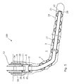
- FIG. 1 shows a cross-sectional view of a first production casing being inserted into a borehole of a well
- FIG. 2 shows a cross-sectional view of the first production casing having annular barriers being expanded to pressure against a wall of the borehole
- FIG. 3 shows a cross-sectional view of the well in which a first barrier packer has been set between an intermediate casing and the first production casing
- FIG. 4 shows a cross-sectional view of the well in which a second production casing has been installed in the intermediate casing and a second barrier packer has been set between the intermediate casing and the second production casing,
- FIG. 5 shows a cross-sectional view of the well in which a drill head at the top of the well has been removed before being replaced with a well head
- FIG. 6 shows a cross-sectional view of the well in which the drill head has been replaced with the well head
- FIG. 7 shows a cross-sectional view of the well in which the first casing has been provided with openings and production of hydrocarbon containing fluid flows through the openings in two production zones between expanded annular barriers
- FIG. 8A shows a cross-sectional view of the top of an embodiment of the well in which two annular barriers arranged surrounding the intermediate casing have been expanded into the surrounding cement in order to provide a well barrier
- FIG. 8B shows a cross-sectional view of the top of another embodiment of the well in which two annular barriers arranged surrounding a first intermediate casing have been expanded into the surrounding cement in order to provide a well barrier between two intermediate casings,
- FIG. 9 shows a cross-sectional view of the well, illustrating the first production casing being rotated while being inserted into the borehole, and
- FIG. 10 shows a cross-sectional view of an expanded annular barrier.
- FIG. 1 shows a completion system 100 being completed.
- the drill head 6 is arranged at a top 7 of the well in a first part 18 of a borehole 4 and on top of a conductor pipe 8 .
- the conductor pipe 8 is cemented to form a seal against an inner wall 9 of the borehole 4 and is at its top connected with the drill head 6 .
- an intermediate casing 11 is arranged, still at the top 7 of the well.
- the intermediate casing 11 is also cemented to form a seal between the conductor pipe 8 and the intermediate casing.
- the intermediate casing 11 is also at its top end 12 connected with the drill head 6 .
- a drill pipe 10 is connected at a first end 13 with a first end 20 of a first production casing 3 .
- a second end 14 is connected with a pump (not shown) for pressurising the drill pipe 6 and thus the first production casing 3 .
- the production casing 3 and the drill pipe 10 are connected by means of a running tool 15 or a similar connection.
- the first production casing 3 comprises several annular barriers 17 which in FIG. 1 are unexpanded while being inserted through the drill head 6 down into the intermediate casing 11 , and a main part of the first production casing 3 is introduced in a second part 19 of the borehole, forming an annulus 16 with the inner wall 9 of the borehole 4 and thus the formation 2 . While inserting the first production casing 3 in the borehole 4 , a second end 21 of the first production casing 3 furthest away from the top 7 of the well is open.
- FIG. 10 shows an enlarged view of the annular barrier 17 in its expanded condition, where an expandable sleeve 22 surrounding a tubular part 23 abuts and pressures against the inner wall 9 of the borehole 4 .
- the expanded annular barrier 17 thus creates a seal between the casing and the inner wall 9 of the borehole 4 and divides the annulus 16 into a first production zone 24 and a second production zone 25 .
- the expandable sleeve 22 is connected with the tubular part 23 by means of two connection parts 26 and forms an expandable space 27 into which fluid flows from an inside of the tubular part through an opening 28 and into the space to expand the expandable sleeve 22 and thus the annular barrier 17 .
- the expandable sleeve 22 may be made of metal and have circumferential seals arranged on its outer face.
- the second end 21 of the first production casing 3 is sealed by dropping a ball 29 into the fluid 30 in the drill pipe 10 .
- the ball 29 flows down the well until it seats in a seat 42 arranged in the second end 21 of the first production casing 3 .
- the first production casing 3 and the drill pipe 10 are pressurised from within, creating an increased pressure expanding the expandable annular barriers 17 until they abut the inner wall 9 of the borehole 4 and thus divide the annulus 16 into several production zones.
- the drill pipe 10 and the first production casing 3 are pressurised to a first predetermined pressure, and the first production casing 3 is tested by measuring if the first predetermined pressure is kept constant during a predetermined time period. If the pressure drops during this time period, it means that the first production casing 3 is leaking, and if the pressure is maintained without having to pump any further, it means that the first production casing 3 is tight and forms a so-called “solid casing”, and that it is thus comparable with just a plain metal casing without any implemented components, such as sleeve, barriers or the like.
- a first barrier packer 31 is set between the first production casing and the intermediate casing 11 , as shown in FIG. 3 , if it was not already set before testing the first production casing 3 . Then, the drill pipe 10 is disconnected and the first production casing 3 and the intermediate casing 11 are pressurised from within to a second predetermined pressure, and the first barrier packer 31 is tested by measuring if the second predetermined pressure is kept constant during a predetermined time period.
- the intermediate casing 11 is pressurised from within to a second predetermined pressure so that the annular space 32 between the intermediate casing 11 and the drill pipe 10 is pressurised to the second predetermined pressure for a period of time, and the first barrier packer 31 is tested by measuring if the second predetermined pressure is kept constant during a predetermined time period.
- packers and other “barriers” are set, but they are not tested, and it is therefore uncertain whether they are in fact barriers.
- a second production casing 33 having a plug 34 and a downhole safety valve 36 is inserted into the well, as shown in FIG. 4 .
- the plug 34 and the downhole safety valve 36 are both arranged within the second production casing 33 , and the downhole safety valve 36 is arranged closer to the top 7 of the well than the plug 34 .
- the downhole safety valve 36 is arranged approximately 200-300 meters down the second production casing from the top of the well.
- the second production casing 33 is arranged above the first production casing 3 and is thus closer to the top 7 of the well than the first production casing 3 .
- a second barrier packer 35 is subsequently set in an annular space 39 between the second production casing 33 and the intermediate casing 11 .
- the annular space 39 is pressurised from within to a third predetermined pressure, and the second barrier packer 35 is tested by measuring if the third predetermined pressure is kept constant during a predetermined time period.
- the plug 34 may a conventional glass plug or a formation isolation valve, also called a formation isolation valve (FIV).
- the downhole safety valve 36 is opened and the second production casing 33 is pressurised from within to a fourth predetermined pressure, and the plug 34 is tested by measuring if the fourth predetermined pressure is kept constant during a predetermined time period. If the pressure is maintained during the predetermined period of time, it means that the plug 34 is a tight barrier. Subsequently, the downhole safety valve 36 is closed again, and now, five barriers have been tested.
- the second production casing 33 above the downhole safety valve 36 is pressurised from within to a fifth predetermined pressure, and the downhole safety valve 36 is tested by measuring if the fifth predetermined pressure is kept constant during a predetermined time period and thus if the downhole safety valve 36 is tight and consequently a barrier.
- a downhole safety valve 36 proven to be a barrier closes the well sufficiently to replace the drill head with the well head which is to be used during production, as shown in FIG. 5 where the drill head has been removed.
- the annular space 39 between the second production casing 33 and the intermediate casing 11 is pressurised from within to a sixth predetermined pressure, and the second barrier packer 35 is tested again after replacing the drill head. This is done in the same way as described above, i.e. by measuring if the sixth predetermined pressure is kept constant during a predetermined time period, and if the pressure is maintained, it means that the well head 37 has been successfully connected with the intermediate casing 11 .
- the space above the downhole safety valve 36 and/or the plug 34 may be filled with a so-called heavy fluid in order to prevent a blowout.
- the heavy fluid is subsequently sucked out after having replaced the drill head with the well head 37 .
- the second production casing 33 above the downhole safety valve 36 is pressurised from within to a seventh predetermined pressure, and the downhole safety valve 36 is tested by measuring if the seventh predetermined pressure is kept constant during a predetermined time period. If both the sixth and the seventh pressure are maintained during the corresponding predetermined period of time, it means that the well head 37 has been successfully connected, as shown in FIG. 6 .
- the intermediate casing 11 comprises two annular barriers 17 .
- the annular barriers 17 of the intermediate casing 11 are expanded to abut the inner wall 9 of the borehole 4 , displacing the non-cured cement so that a pressure increase is created in the barrier space 40 between the annular barriers 17 .
- the annular space 44 is pressurised from within to an eight predetermined pressure, and the annular barriers 17 are tested by measuring if the eight predetermined pressure is kept constant for a period of time, e.g.
- annular barriers 17 By arranging the annular barriers 17 in the cement abutting the borehole, a defective cement job does not jeopardise the well safety since the annular barriers arranged between the intermediate casing 11 and the borehole wall provide a sufficient seal.
- At least one annular barrier 17 may also be arranged between the intermediate casing 11 and a second intermediate casing 41 .
- FIG. 8B two annular barriers 17 are shown. The barriers 17 are tested by pressurising the annular space 44 between the first intermediate casing 11 and second intermediate casing 41 and monitoring if the pressure drops during a predetermined period of time.
- the space below the annular barriers of FIG. 8B is filled with cement.
- the well has now been completed and the components and their mutual connections have been tested to confirm that the barriers are in fact barriers, and the well is now ready for initiating production, as shown in FIG. 7 .
- the plug 34 arranged in the second production casing 33 is removed.
- apertures 38 need to be provided in the first production casing 3 .
- the apertures 38 are provided by punching or drilling holes in the wall of the first production casing 3 to provide access from the inside of the casing and the annulus 16 .
- the first production casing 3 has sliding sleeves (not shown) covering the aperture already present in the casing, and thus, the sliding sleeves need to be activated to provide access to the annulus 16 , e.g. by inserting a key tool pulling and sliding the sleeves to its open position.
- the first production casing 3 may also be perforated by a conventional perforating tool, however, such perforations may injure the barriers tested as described above.
- the stimulation of the well is performed by injecting stimulation fluid out through the apertures 38 and into the borehole 4 .
- the stimulation fluid may be a fracking fluid used to provide fractures in the formation, and the fracking fluid may comprise proppants.
- the stimulation fluid may also be an acid.
- the first production casing 3 may be rotated while inserting the first production casing in order to easily force the casing forward in the borehole 4 .
- the second end 21 of the first production casing 3 comprises exterior edges 43 which are adapted to function as a “drill head” during the insertion of the production casing 3 into the second part 19 of the borehole 4 .
- first end 20 of the first production casing 3 may have an enlarged diameter (not shown), enabling the end of the second production casing 33 to fit inside the first end of the first production casing.
- the end of the second production casing may thus be “snuck-fitted” into the first production casing 3 . Having such a fitted connection between the production casings prevents a tool, e.g. a tool connected with a downhole tractor, submerged in later operation from getting stuck in the gap between the two production casings, as shown in FIG. 7 .
- a flushing fluid may be injected from the second end of the first production casing 3 to perform a clean-out by flushing most of the drilling mud outside the first production casing 3 along the outside of the first production casing 3 and along the outside of the drill pipe.
- the second end 21 of the first production casing 3 may also be sealed by inserting a plug, such as a swellable plug or another type drop device, into the opening at the second end 21 of the first production casing 3 .
- a plug such as a swellable plug or another type drop device
- the intermediate casing 11 and the first and second production casings 3 , 33 are made of metal like the annular barriers 17 .
- the first and/or second barrier packers 31 , 35 may be an expandable annular barrier 17 .
- the data obtained during testing of the first production casing 3 , the first barrier packer 31 , the second barrier packer 35 , the plug 34 , the downhole safety valve 36 and the annular barriers 17 , respectively, are stored.
- the well shown in FIG. 7 is thus a completion system 100 obtained by the method described above.
- the invention also relates to the oil production facilitated by the above method.
- fluid or well fluid any kind of fluid that may be present in oil or gas wells downhole, such as natural gas, oil, oil mud, crude oil, water, etc.
- gas is meant any kind of gas composition present in a well, completion, or open hole
- oil is meant any kind of oil composition, such as crude oil, an oil-containing fluid, etc.
- Gas, oil, and water fluids may thus all comprise other elements or substances than gas, oil, and/or water, respectively.
- a casing any kind of pipe, tubing, tubular, liner, string etc. used downhole in relation to oil or natural gas production.
- a downhole tractor can be used to push the tool all the way into position in the well.
- the downhole tractor may have projectable arms having wheels, wherein the wheels contact the inner surface of the casing for propelling the tractor and the tool forward in the casing.
- a downhole tractor is any kind of driving tool capable of pushing or pulling tools in a well downhole, such as a Well Tractor®.
Landscapes
- Geology (AREA)
- Life Sciences & Earth Sciences (AREA)
- Engineering & Computer Science (AREA)
- Mining & Mineral Resources (AREA)
- Physics & Mathematics (AREA)
- General Life Sciences & Earth Sciences (AREA)
- Fluid Mechanics (AREA)
- Environmental & Geological Engineering (AREA)
- Geochemistry & Mineralogy (AREA)
- Geophysics (AREA)
- Examining Or Testing Airtightness (AREA)
- Investigating Strength Of Materials By Application Of Mechanical Stress (AREA)
- Consolidation Of Soil By Introduction Of Solidifying Substances Into Soil (AREA)
- Earth Drilling (AREA)
- Filling Or Discharging Of Gas Storage Vessels (AREA)
- Measuring Fluid Pressure (AREA)
- Investigation Of Foundation Soil And Reinforcement Of Foundation Soil By Compacting Or Drainage (AREA)
Abstract
Description
-
- connecting a drill pipe with a first end of a first production casing having annular barriers, which annular barriers comprise a tubular part forming part of the casing and an expandable sleeve circumferenting the tubular part, thereby defining an expandable space,
- inserting the drill pipe and the first production casing via a drill head arranged at a top of the well into an intermediate casing extending in a first part of the borehole closest to the top of the well and at least part of the first production casing into a second part of the borehole,
- sealing a second end of the first production casing,
- pressurising the first production casing from within and expanding one or more of the expandable sleeves of the annular barriers to abut a wall of the borehole,
- pressurising the first production casing from within to a predetermined pressure, and
- testing the first production casing after expansion by measuring if the predetermined pressure is kept constant during a predetermined time period.
Claims (16)
Applications Claiming Priority (4)
| Application Number | Priority Date | Filing Date | Title |
|---|---|---|---|
| EP12190841.2A EP2728111A1 (en) | 2012-10-31 | 2012-10-31 | Pressure barrier testing method |
| EP12190841.2 | 2012-10-31 | ||
| EP12190841 | 2012-10-31 | ||
| PCT/EP2013/072699 WO2014067992A2 (en) | 2012-10-31 | 2013-10-30 | Barrier testing method |
Publications (2)
| Publication Number | Publication Date |
|---|---|
| US20150300154A1 US20150300154A1 (en) | 2015-10-22 |
| US9835023B2 true US9835023B2 (en) | 2017-12-05 |
Family
ID=47146207
Family Applications (1)
| Application Number | Title | Priority Date | Filing Date |
|---|---|---|---|
| US14/439,316 Active 2034-08-22 US9835023B2 (en) | 2012-10-31 | 2013-10-30 | Barrier testing method |
Country Status (11)
| Country | Link |
|---|---|
| US (1) | US9835023B2 (en) |
| EP (3) | EP2728111A1 (en) |
| CN (1) | CN104755700B (en) |
| AU (1) | AU2013340898B2 (en) |
| BR (1) | BR112015009596B1 (en) |
| CA (1) | CA2887698A1 (en) |
| MX (1) | MX355083B (en) |
| MY (1) | MY178594A (en) |
| RU (1) | RU2660704C2 (en) |
| SA (1) | SA515360364B1 (en) |
| WO (1) | WO2014067992A2 (en) |
Cited By (3)
| Publication number | Priority date | Publication date | Assignee | Title |
|---|---|---|---|---|
| US11739607B2 (en) | 2021-12-02 | 2023-08-29 | Saudi Arabian Oil Company | Multi-expansion packer system having an expandable inner part disposed within an outer part of the packer |
| US20250084736A1 (en) * | 2023-09-08 | 2025-03-13 | Welltec Manufacturing Center Completions ApS | Annular barrier and downhole system |
| US12601237B2 (en) | 2022-04-26 | 2026-04-14 | Conocophillips Company | Temporary suspension of completed hydrocarbon wells |
Families Citing this family (20)
| Publication number | Priority date | Publication date | Assignee | Title |
|---|---|---|---|---|
| EP3088655A1 (en) * | 2015-04-29 | 2016-11-02 | Welltec A/S | Downhole tubular assembly of a well tubular structure |
| RU2726710C2 (en) * | 2015-08-17 | 2020-07-15 | Веллтек Ойлфилд Солюшнс АГ | Well completion system providing tightness relative to coating layer |
| EP3159478A1 (en) * | 2015-10-23 | 2017-04-26 | Welltec A/S | Downhole completion system sealing against the cap layer |
| BR112018011001A2 (en) * | 2015-12-18 | 2018-12-04 | Welltec As | downhole system |
| EP3249152A1 (en) * | 2016-05-27 | 2017-11-29 | Welltec A/S | Downhole system for remedial treatment |
| EP3263829A1 (en) * | 2016-06-28 | 2018-01-03 | Welltec A/S | Downhole drilling system |
| GB2555637B (en) | 2016-11-07 | 2019-11-06 | Equinor Energy As | Method of plugging and pressure testing a well |
| EP3327246A1 (en) * | 2016-11-25 | 2018-05-30 | Welltec A/S | Annular barrier with expansion verification |
| BR112019026234B1 (en) | 2017-06-16 | 2023-11-21 | Interwell Norway As | METHOD AND SYSTEM FOR INTEGRITY TESTING |
| EP3536897A1 (en) * | 2018-03-06 | 2019-09-11 | Welltec Oilfield Solutions AG | Offshore method |
| JP7188543B2 (en) * | 2018-03-29 | 2022-12-13 | 国立大学法人九州大学 | Method for isomerizing allyl compound |
| US10941649B2 (en) * | 2018-04-19 | 2021-03-09 | Saudi Arabian Oil Company | Tool for testing within a wellbore |
| EP3575544A1 (en) * | 2018-05-30 | 2019-12-04 | Welltec Oilfield Solutions AG | Downhole completion system |
| CA3121821A1 (en) * | 2018-12-03 | 2020-06-11 | Petroleo Brasileiro S.A. - Petrobras | System and method for detecting the watertightness in the annular space in flexible lines |
| US10961797B2 (en) * | 2019-04-05 | 2021-03-30 | Workover Solutions, Inc. | Integrated milling and production device |
| GB2592635B (en) * | 2020-03-05 | 2022-08-24 | Ardyne Holdings Ltd | Improvements in or relating to wellbore operations |
| CN114151073B (en) * | 2020-09-08 | 2023-11-28 | 中国石油天然气股份有限公司 | Method, device and equipment for evaluating barrier failure result of gas well |
| EP3981947A1 (en) * | 2020-10-06 | 2022-04-13 | Welltec Oilfield Solutions AG | Plug and abandonment system |
| US12529662B2 (en) * | 2022-09-07 | 2026-01-20 | Saudi Arabian Oil Company | Built-in system for inspection, testing and sampling of casted or additive manufactured material |
| CN115584947B (en) * | 2022-09-22 | 2025-05-13 | 国网浙江省电力有限公司金华供电公司 | Anchor hole protection method |
Citations (12)
| Publication number | Priority date | Publication date | Assignee | Title |
|---|---|---|---|---|
| SU1366632A1 (en) | 1986-07-14 | 1988-01-15 | Всесоюзный Научно-Исследовательский Институт Буровой Техники | Method of compression testing of casing with interval-wise packer |
| US4756364A (en) * | 1986-12-10 | 1988-07-12 | Halliburton Company | Packer bypass |
| WO1999032756A1 (en) | 1997-12-22 | 1999-07-01 | Specialised Petroleum Services Limited | Apparatus and method for inflating packers in a well |
| GB2399368A (en) | 2002-04-17 | 2004-09-15 | Schlumberger Holdings | Inflatable and expandable packers |
| US20050028980A1 (en) | 2003-08-08 | 2005-02-10 | Page Peter Ernest | Method of suspending, completing and working over a well |
| RU2262580C1 (en) | 2004-06-16 | 2005-10-20 | Общество с ограниченной ответственностью "АЛ" | Production string leak test method |
| EP1624152A2 (en) | 2004-08-04 | 2006-02-08 | Read Well Services Limited | Hydraulically set casing packer |
| US20070029082A1 (en) * | 2005-08-05 | 2007-02-08 | Giroux Richard L | Apparatus and methods for creation of down hole annular barrier |
| WO2008131771A2 (en) | 2007-04-26 | 2008-11-06 | Welltec A/S | Cladding method and expansion tool |
| US20110011646A1 (en) * | 2000-04-13 | 2011-01-20 | Giroux Richard L | Apparatus and methods for drilling a wellbore using casing |
| EP2466064A1 (en) | 2010-12-17 | 2012-06-20 | Welltec A/S | Casing anchor |
| EP2466065A1 (en) | 2010-12-17 | 2012-06-20 | Welltec A/S | Well completion |
-
2012
- 2012-10-31 EP EP12190841.2A patent/EP2728111A1/en not_active Withdrawn
-
2013
- 2013-10-30 BR BR112015009596-8A patent/BR112015009596B1/en active IP Right Grant
- 2013-10-30 MX MX2015004750A patent/MX355083B/en active IP Right Grant
- 2013-10-30 AU AU2013340898A patent/AU2013340898B2/en active Active
- 2013-10-30 CA CA2887698A patent/CA2887698A1/en not_active Abandoned
- 2013-10-30 CN CN201380056763.1A patent/CN104755700B/en not_active Expired - Fee Related
- 2013-10-30 MY MYPI2015001093A patent/MY178594A/en unknown
- 2013-10-30 EP EP13786216.5A patent/EP2914809B1/en active Active
- 2013-10-30 WO PCT/EP2013/072699 patent/WO2014067992A2/en not_active Ceased
- 2013-10-30 RU RU2015120086A patent/RU2660704C2/en active
- 2013-10-30 US US14/439,316 patent/US9835023B2/en active Active
- 2013-10-30 EP EP24218429.9A patent/EP4517042A3/en not_active Withdrawn
-
2015
- 2015-04-29 SA SA515360364A patent/SA515360364B1/en unknown
Patent Citations (15)
| Publication number | Priority date | Publication date | Assignee | Title |
|---|---|---|---|---|
| SU1366632A1 (en) | 1986-07-14 | 1988-01-15 | Всесоюзный Научно-Исследовательский Институт Буровой Техники | Method of compression testing of casing with interval-wise packer |
| US4756364A (en) * | 1986-12-10 | 1988-07-12 | Halliburton Company | Packer bypass |
| WO1999032756A1 (en) | 1997-12-22 | 1999-07-01 | Specialised Petroleum Services Limited | Apparatus and method for inflating packers in a well |
| US20110011646A1 (en) * | 2000-04-13 | 2011-01-20 | Giroux Richard L | Apparatus and methods for drilling a wellbore using casing |
| GB2399368A (en) | 2002-04-17 | 2004-09-15 | Schlumberger Holdings | Inflatable and expandable packers |
| US20050028980A1 (en) | 2003-08-08 | 2005-02-10 | Page Peter Ernest | Method of suspending, completing and working over a well |
| RU2262580C1 (en) | 2004-06-16 | 2005-10-20 | Общество с ограниченной ответственностью "АЛ" | Production string leak test method |
| EP1624152A2 (en) | 2004-08-04 | 2006-02-08 | Read Well Services Limited | Hydraulically set casing packer |
| US20070029082A1 (en) * | 2005-08-05 | 2007-02-08 | Giroux Richard L | Apparatus and methods for creation of down hole annular barrier |
| WO2008131771A2 (en) | 2007-04-26 | 2008-11-06 | Welltec A/S | Cladding method and expansion tool |
| CN101680282A (en) | 2007-04-26 | 2010-03-24 | 韦尔泰克有限公司 | Cladding method and expansion tool |
| EP2466064A1 (en) | 2010-12-17 | 2012-06-20 | Welltec A/S | Casing anchor |
| EP2466065A1 (en) | 2010-12-17 | 2012-06-20 | Welltec A/S | Well completion |
| WO2012080490A1 (en) | 2010-12-17 | 2012-06-21 | Welltec A/S | Well completion |
| US20130319677A1 (en) * | 2010-12-17 | 2013-12-05 | Welltech A/S | Well completion |
Non-Patent Citations (5)
| Title |
|---|
| International Search Report for PCT/EP2013/072699 dated May 23, 2014, five pages. |
| Notification Concerning Transmittal of Copy of International Preliminary Report on Patentability (Chapter I of the Patent Cooperation Treaty dated May 14, 2015 in International Application No. PCT/EP2013/072699 (8 pages). |
| Notification of the First Office Action dated Jun. 1, 2017 in Chinese Application No. 201380056763.1, with English Translation (14 pages). |
| Office Action of Substantive Examination dated Jun. 8, 2017 in Russian Application No. 2015120086/03(031050), with English Translation (12 pages). |
| Written Opinion of the ISA for PCT/EP2013/072699 dated May 23, 2014, six pages. |
Cited By (4)
| Publication number | Priority date | Publication date | Assignee | Title |
|---|---|---|---|---|
| US11739607B2 (en) | 2021-12-02 | 2023-08-29 | Saudi Arabian Oil Company | Multi-expansion packer system having an expandable inner part disposed within an outer part of the packer |
| US12601237B2 (en) | 2022-04-26 | 2026-04-14 | Conocophillips Company | Temporary suspension of completed hydrocarbon wells |
| US20250084736A1 (en) * | 2023-09-08 | 2025-03-13 | Welltec Manufacturing Center Completions ApS | Annular barrier and downhole system |
| US12486737B2 (en) * | 2023-09-08 | 2025-12-02 | Welltec Manufacturing Center Completions ApS | Annular barrier and downhole system |
Also Published As
| Publication number | Publication date |
|---|---|
| AU2013340898A1 (en) | 2015-04-16 |
| CN104755700A (en) | 2015-07-01 |
| RU2660704C2 (en) | 2018-07-09 |
| WO2014067992A3 (en) | 2014-07-31 |
| SA515360364B1 (en) | 2018-10-21 |
| WO2014067992A2 (en) | 2014-05-08 |
| EP2914809A2 (en) | 2015-09-09 |
| MX2015004750A (en) | 2015-07-21 |
| US20150300154A1 (en) | 2015-10-22 |
| BR112015009596A2 (en) | 2017-07-04 |
| MX355083B (en) | 2018-04-04 |
| EP4517042A2 (en) | 2025-03-05 |
| EP2728111A1 (en) | 2014-05-07 |
| MY178594A (en) | 2020-10-16 |
| AU2013340898B2 (en) | 2016-05-12 |
| EP2914809B1 (en) | 2026-03-25 |
| CN104755700B (en) | 2019-01-11 |
| BR112015009596B1 (en) | 2021-01-05 |
| RU2015120086A (en) | 2016-12-20 |
| CA2887698A1 (en) | 2014-05-08 |
| EP4517042A3 (en) | 2025-05-28 |
Similar Documents
| Publication | Publication Date | Title |
|---|---|---|
| US9835023B2 (en) | Barrier testing method | |
| EP3408494B1 (en) | Annular barrier and downhole system for low pressure zone | |
| US8240387B2 (en) | Casing annulus tester for diagnostics and testing of a wellbore | |
| US9822632B2 (en) | Method of pressure testing a plugged well | |
| US20160208569A1 (en) | Sealing insert and method | |
| CN109844257B (en) | Well control using improved liner tieback | |
| US10400556B2 (en) | Downhole completion system sealing against the cap layer | |
| US10184321B2 (en) | Mitigating leaks in production tubulars | |
| EP3159478A1 (en) | Downhole completion system sealing against the cap layer | |
| EP3475522B1 (en) | Downhole drilling system | |
| Schnitzler et al. | First Openhole Intelligent Well Completion in Brazilian Pre-Salt | |
| US20190277107A1 (en) | Offshore method |
Legal Events
| Date | Code | Title | Description |
|---|---|---|---|
| AS | Assignment |
Owner name: WELLTEC A/S, DENMARK Free format text: ASSIGNMENT OF ASSIGNORS INTEREST;ASSIGNOR:HALLUNDBAEK, JOERGEN;REEL/FRAME:035524/0412 Effective date: 20150414 Owner name: WELLTEC A/S, DENMARK Free format text: ASSIGNMENT OF ASSIGNORS INTEREST;ASSIGNORS:VASQUES, RICARDO REVES;HAZEL, PAUL;REEL/FRAME:035532/0578 Effective date: 20150428 |
|
| STCF | Information on status: patent grant |
Free format text: PATENTED CASE |
|
| AS | Assignment |
Owner name: WELLTEC OILFIELD SOLUTIONS AG, SWITZERLAND Free format text: ASSIGNMENT OF ASSIGNORS INTEREST;ASSIGNOR:WELLTEC A/S;REEL/FRAME:047724/0079 Effective date: 20181008 |
|
| AS | Assignment |
Owner name: WELLTEC OILFIELD SOLUTIONS AG, SWITZERLAND Free format text: CHANGE OF ADDRESS;ASSIGNOR:WELLTEC OILFIELD SOLUTIONS AG;REEL/FRAME:048853/0289 Effective date: 20190401 |
|
| MAFP | Maintenance fee payment |
Free format text: PAYMENT OF MAINTENANCE FEE, 4TH YEAR, LARGE ENTITY (ORIGINAL EVENT CODE: M1551); ENTITY STATUS OF PATENT OWNER: LARGE ENTITY Year of fee payment: 4 |
|
| AS | Assignment |
Owner name: WELLTEC MANUFACTURING CENTER COMPLETIONS APS, DENMARK Free format text: ASSIGNMENT OF ASSIGNORS INTEREST;ASSIGNOR:WELLTEC A/S;REEL/FRAME:069327/0618 Effective date: 20240314 |
|
| MAFP | Maintenance fee payment |
Free format text: PAYMENT OF MAINTENANCE FEE, 8TH YEAR, LARGE ENTITY (ORIGINAL EVENT CODE: M1552); ENTITY STATUS OF PATENT OWNER: LARGE ENTITY Year of fee payment: 8 |