US9834288B1 - Hydraulic drives for use in charging systems, ballast systems, or other systems of underwater vehicles - Google Patents
Hydraulic drives for use in charging systems, ballast systems, or other systems of underwater vehicles Download PDFInfo
- Publication number
- US9834288B1 US9834288B1 US15/173,214 US201615173214A US9834288B1 US 9834288 B1 US9834288 B1 US 9834288B1 US 201615173214 A US201615173214 A US 201615173214A US 9834288 B1 US9834288 B1 US 9834288B1
- Authority
- US
- United States
- Prior art keywords
- tank
- water
- refrigerant
- hydraulic drive
- channel
- Prior art date
- Legal status (The legal status is an assumption and is not a legal conclusion. Google has not performed a legal analysis and makes no representation as to the accuracy of the status listed.)
- Active
Links
Images


Classifications
-
- B—PERFORMING OPERATIONS; TRANSPORTING
- B63—SHIPS OR OTHER WATERBORNE VESSELS; RELATED EQUIPMENT
- B63G—OFFENSIVE OR DEFENSIVE ARRANGEMENTS ON VESSELS; MINE-LAYING; MINE-SWEEPING; SUBMARINES; AIRCRAFT CARRIERS
- B63G8/00—Underwater vessels, e.g. submarines; Equipment specially adapted therefor
- B63G8/08—Propulsion
-
- B—PERFORMING OPERATIONS; TRANSPORTING
- B63—SHIPS OR OTHER WATERBORNE VESSELS; RELATED EQUIPMENT
- B63G—OFFENSIVE OR DEFENSIVE ARRANGEMENTS ON VESSELS; MINE-LAYING; MINE-SWEEPING; SUBMARINES; AIRCRAFT CARRIERS
- B63G8/00—Underwater vessels, e.g. submarines; Equipment specially adapted therefor
- B63G8/14—Control of attitude or depth
-
- B—PERFORMING OPERATIONS; TRANSPORTING
- B63—SHIPS OR OTHER WATERBORNE VESSELS; RELATED EQUIPMENT
- B63G—OFFENSIVE OR DEFENSIVE ARRANGEMENTS ON VESSELS; MINE-LAYING; MINE-SWEEPING; SUBMARINES; AIRCRAFT CARRIERS
- B63G8/00—Underwater vessels, e.g. submarines; Equipment specially adapted therefor
- B63G8/001—Underwater vessels adapted for special purposes, e.g. unmanned underwater vessels; Equipment specially adapted therefor, e.g. docking stations
-
- B—PERFORMING OPERATIONS; TRANSPORTING
- B63—SHIPS OR OTHER WATERBORNE VESSELS; RELATED EQUIPMENT
- B63G—OFFENSIVE OR DEFENSIVE ARRANGEMENTS ON VESSELS; MINE-LAYING; MINE-SWEEPING; SUBMARINES; AIRCRAFT CARRIERS
- B63G8/00—Underwater vessels, e.g. submarines; Equipment specially adapted therefor
- B63G8/14—Control of attitude or depth
- B63G8/22—Adjustment of buoyancy by water ballasting; Emptying equipment for ballast tanks
-
- B—PERFORMING OPERATIONS; TRANSPORTING
- B63—SHIPS OR OTHER WATERBORNE VESSELS; RELATED EQUIPMENT
- B63H—MARINE PROPULSION OR STEERING
- B63H19/00—Marine propulsion not otherwise provided for
-
- B—PERFORMING OPERATIONS; TRANSPORTING
- B63—SHIPS OR OTHER WATERBORNE VESSELS; RELATED EQUIPMENT
- B63H—MARINE PROPULSION OR STEERING
- B63H25/00—Steering; Slowing-down otherwise than by use of propulsive elements; Dynamic anchoring, i.e. positioning vessels by means of main or auxiliary propulsive elements
- B63H25/06—Steering by rudders
- B63H25/38—Rudders
-
- F—MECHANICAL ENGINEERING; LIGHTING; HEATING; WEAPONS; BLASTING
- F01—MACHINES OR ENGINES IN GENERAL; ENGINE PLANTS IN GENERAL; STEAM ENGINES
- F01K—STEAM ENGINE PLANTS; STEAM ACCUMULATORS; ENGINE PLANTS NOT OTHERWISE PROVIDED FOR; ENGINES USING SPECIAL WORKING FLUIDS OR CYCLES
- F01K1/00—Steam accumulators
- F01K1/12—Multiple accumulators; Charging, discharging or control specially adapted therefor
-
- F—MECHANICAL ENGINEERING; LIGHTING; HEATING; WEAPONS; BLASTING
- F01—MACHINES OR ENGINES IN GENERAL; ENGINE PLANTS IN GENERAL; STEAM ENGINES
- F01K—STEAM ENGINE PLANTS; STEAM ACCUMULATORS; ENGINE PLANTS NOT OTHERWISE PROVIDED FOR; ENGINES USING SPECIAL WORKING FLUIDS OR CYCLES
- F01K15/00—Adaptations of plants for special use
- F01K15/02—Adaptations of plants for special use for driving vehicles, e.g. locomotives
- F01K15/04—Adaptations of plants for special use for driving vehicles, e.g. locomotives the vehicles being waterborne vessels
-
- F—MECHANICAL ENGINEERING; LIGHTING; HEATING; WEAPONS; BLASTING
- F01—MACHINES OR ENGINES IN GENERAL; ENGINE PLANTS IN GENERAL; STEAM ENGINES
- F01K—STEAM ENGINE PLANTS; STEAM ACCUMULATORS; ENGINE PLANTS NOT OTHERWISE PROVIDED FOR; ENGINES USING SPECIAL WORKING FLUIDS OR CYCLES
- F01K25/00—Plants or engines characterised by use of special working fluids, not otherwise provided for; Plants operating in closed cycles and not otherwise provided for
- F01K25/08—Plants or engines characterised by use of special working fluids, not otherwise provided for; Plants operating in closed cycles and not otherwise provided for using special vapours
- F01K25/10—Plants or engines characterised by use of special working fluids, not otherwise provided for; Plants operating in closed cycles and not otherwise provided for using special vapours the vapours being cold, e.g. ammonia, carbon dioxide, ether
- F01K25/103—Carbon dioxide
-
- B—PERFORMING OPERATIONS; TRANSPORTING
- B63—SHIPS OR OTHER WATERBORNE VESSELS; RELATED EQUIPMENT
- B63G—OFFENSIVE OR DEFENSIVE ARRANGEMENTS ON VESSELS; MINE-LAYING; MINE-SWEEPING; SUBMARINES; AIRCRAFT CARRIERS
- B63G8/00—Underwater vessels, e.g. submarines; Equipment specially adapted therefor
- B63G8/001—Underwater vessels adapted for special purposes, e.g. unmanned underwater vessels; Equipment specially adapted therefor, e.g. docking stations
- B63G2008/002—Underwater vessels adapted for special purposes, e.g. unmanned underwater vessels; Equipment specially adapted therefor, e.g. docking stations unmanned
Definitions
- This disclosure generally relates to underwater vehicles. More specifically, this disclosure relates to hydraulic drives for use in charging systems, ballast systems, or other systems of underwater vehicles.
- Unmanned underwater vehicles can be used in a number of applications, such as undersea surveying, recovery, or surveillance operations.
- supplying adequate power to UUVs for prolonged operation can be problematic.
- one prior approach simply tethers a UUV to a central power plant and supplies power to the UUV through the tether.
- Another prior approach uses expanding wax based on absorbed heat to generate power, but this approach provides power in very small amounts, typically limited to less than about 200 Watts (W) at a 2.2 Watt-hour (WHr) capacity.
- Yet another prior approach involves using fuel cells in a UUV to generate power, but fuel cells typically require large packages and substantial space. It is also often necessary or desirable to provide ballast systems on UUVs in order to help stabilize the UUVs and provide buoyance management during use.
- This disclosure provides hydraulic drives for use in charging systems, ballast systems, or other systems of underwater vehicles.
- an apparatus in a first embodiment, includes first and second tanks each configured to receive and store a refrigerant under pressure.
- the apparatus also includes at least one generator configured to receive flows of the refrigerant between the tanks and to generate electrical power based on the flows of the refrigerant.
- the apparatus further includes first and second hydraulic drives associated with the first and second tanks, respectively.
- Each hydraulic drive includes a first piston within the associated tank, a channel fluidly coupled to the associated tank and configured to contain hydraulic fluid, and a second piston within the channel and configured to move within the channel in order to vary an amount of the hydraulic fluid within the associated tank and vary a position of the first piston within the associated tank.
- the channel of each hydraulic drive has a cross-sectional area that is less than a cross-sectional area of the associated tank.
- a system in a second embodiment, includes an underwater vehicle having a body, fins projecting from the body, and a power generator.
- the power generator includes first and second tanks each configured to receive and store a refrigerant under pressure.
- the power generator also includes at least one generator configured to receive flows of the refrigerant between the tanks and to generate electrical power based on the flows of the refrigerant.
- the power generator further includes first and second hydraulic drives associated with the first and second tanks, respectively.
- Each hydraulic drive includes a first piston within the associated tank, a channel fluidly coupled to the associated tank and configured to contain hydraulic fluid, and a second piston within the channel and configured to move within the channel in order to vary an amount of the hydraulic fluid within the associated tank and vary a position of the first piston within the associated tank.
- the channel of each hydraulic drive has a cross-sectional area that is less than a cross-sectional area of the associated tank.
- an apparatus in a third embodiment, includes a cavity configured to receive a material and a hydraulic drive.
- the hydraulic drive includes a first piston within the cavity, a channel fluidly coupled to the cavity and configured to contain hydraulic fluid, and a second piston within the channel and configured to move within the channel in order to vary an amount of the hydraulic fluid within the cavity, vary a position of the first piston within the cavity, and vary an amount of the material within the cavity.
- the channel of the hydraulic drive has a cross-sectional area that is less than a cross-sectional area of the cavity.
- FIGS. 1A through 1D illustrate a first example underwater vehicle having one or more hydraulic drives in accordance with this disclosure
- FIGS. 2A through 2C illustrate a second example underwater vehicle having one or more hydraulic drives in accordance with this disclosure
- FIG. 3 illustrates example components of an underwater vehicle having one or more hydraulic drives in accordance with this disclosure
- FIGS. 4 through 5G illustrate an example charging system for periodically charging an underwater vehicle in accordance with this disclosure
- FIG. 6 illustrates an example method for periodically charging an underwater vehicle in accordance with this disclosure
- FIGS. 7A through 7C illustrate an example ballast system for an underwater vehicle in accordance with this disclosure.
- FIG. 8 illustrates an example method for stabilizing an underwater vehicle using a ballast system in accordance with this disclosure.
- FIGS. 1 through 8 described below, and the various embodiments used to describe the principles of the present invention in this patent document are by way of illustration only and should not be construed in any way to limit the scope of the invention. Those skilled in the art will understand that the principles of the present invention may be implemented in any type of suitably arranged device or system.
- FIGS. 1A through 1D illustrate a first example underwater vehicle 100 having one or more hydraulic drives in accordance with this disclosure.
- the vehicle 100 denotes an unmanned underwater vehicle or other device that can function as both a buoy and a glider within an ocean or other body of water.
- the vehicle 100 could be used to support various functions, such as undersea surveying, recovery, or surveillance operations.
- the vehicle 100 includes a body 102 having fins 104 a - 104 b and wings 106 .
- the body 102 denotes any suitable structure configured to encase, protect, or otherwise contain other components of the vehicle 100 .
- the body 102 could be formed from any suitable material(s) and in any suitable manner.
- the body 102 can be formed so that the vehicle 100 is able to withstand extremely elevated pressures found at deep depths in an ocean or other body of water. In some embodiments, the body 102 could allow the vehicle 100 to operate at depths of up to 1,000 meters or more.
- the fins 104 a - 104 b denote projections from the body 102 that help to stabilize the body 102 during travel.
- Each of the fins 104 a - 104 b could be formed from any suitable material(s) and in any suitable manner.
- each of the fins 104 a - 104 b could have any suitable size, shape, and dimensions.
- at least some of the fins 104 a - 104 b could be movable or adjustable to help alter the course of the body 102 and to steer the body 102 through water during travel.
- the numbers and positions of the fins 104 a - 104 b shown here are examples only, and any numbers and positions of fins could be used to support desired operations of the vehicle 100 .
- the underwater vehicle 100 can both ascend and descend within a body of water during use.
- the fins 104 a could be used to steer the vehicle 100 while ascending, and the fins 104 b could be used to steer the vehicle 100 while descending.
- the fins 104 a can be used to control the pitch of the vehicle 100
- a differential between the fins 104 a can be used to control the roll of the vehicle 100 .
- the fins 104 b can be used to control the pitch of the vehicle 100
- a differential between the fins 104 b can be used to control the roll of the vehicle 100 .
- the wings 106 support gliding movement of the vehicle 100 underwater.
- the wings 106 are moveable to support different directions of travel. For example, the wings 106 are swept downward in FIG. 1A when the vehicle 100 is ascending, and the wings 106 are swept upward in FIG. 1B when the vehicle 100 is descending. In this way, the wings 106 help to facilitate easier or more rapid movement of the vehicle 100 while ascending or descending.
- Each of the wings 106 could be formed from any suitable material(s) and in any suitable manner. Also, each of the wings 106 could have any suitable size, shape, and dimensions.
- the number and positions of the wings 106 shown here are examples only, and any number and positions of wings could be used to support desired operations of the vehicle 100 .
- the underwater vehicle 100 may further include one or more ballasts 108 a - 108 b , which help to control the center of gravity of the vehicle 100 .
- material can move within a power supply or other portion of the vehicle 100 , and that movement can alter the center of gravity of the vehicle 100 .
- Underwater gliders can be particularly susceptible to changes in their centers of gravity, so the vehicle 100 can adjust one or more of the ballasts 108 a - 108 b as needed or desired (such as during ascent or descent) to maintain the center of gravity of the vehicle 100 substantially at a desired location.
- the ballasts 108 a - 108 b are located on opposite sides of the vehicle's power supply along a length of the vehicle 100 .
- Each ballast 108 a - 108 b includes any suitable structure configured to modify the center of gravity of an underwater vehicle. Note that the number and positions of the ballasts 108 a - 108 b shown here are examples only, and any number and positions of ballasts could be used in the vehicle 100 .
- FIGS. 1C and 1D illustrate different possible end views of the underwater vehicle 100 .
- the wings 106 are positioned and extend from the body 102 along a line through a center of the body 102 .
- the wings 106 are positioned and extend from the body 102 along a line tangential to the body 102 . In either case, the wings 106 can be stowed in a folded position where the wings 106 extend along the length of the body 102 and later unfolded before, during, or after deployment.
- FIGS. 2A through 2C illustrate a second example underwater vehicle 200 having one or more hydraulic drives in accordance with this disclosure.
- the vehicle 200 denotes an unmanned underwater vehicle or other device that can function as a buoy within an ocean or other body of water.
- the vehicle 200 could be used to support various functions, such as undersea surveying, recovery, or surveillance operations.
- the underwater vehicle 200 includes a body 202 and fins 204 a - 204 b .
- the body 202 denotes any suitable structure configured to encase, protect, or otherwise contain other components of the vehicle 200 .
- the body 202 could be formed from any suitable material(s) and in any suitable manner.
- the fins 204 a - 204 b denote projections from the body 202 that help to stabilize the body 202 during travel.
- Each of the fins 204 a - 204 b could be formed from any suitable material(s) and in any suitable manner.
- each of the fins 204 a - 204 b could have any suitable size, shape, and dimensions.
- the fins 204 a - 204 b could be movable or adjustable to help alter the course of the body 202 and to steer the body 102 through water during travel.
- the numbers and positions of the fins 204 a - 204 b shown here are examples only, and any numbers and positions of fins could be used to support desired operations of the vehicle 200 .
- the vehicle 200 may further include one or more ballasts 208 a - 208 b , which help to control the center of gravity of the vehicle 200 .
- the underwater vehicle 200 lacks wings used to support gliding of the vehicle 200 through water.
- the vehicle 200 denotes a device that can function as a buoy but generally not as a glider within an ocean or other body of water.
- each underwater vehicle 100 or 200 shown in FIGS. 1A through 2C could remain generally vertical during normal operation.
- the vehicle 100 or 200 is generally operating as a buoy and can collect information or perform other tasks.
- exact vertical orientation is not required during operation of the vehicle 100 or 200 .
- the vehicle 100 or 200 can travel through the water to the surface or to a desired depth of the water. While submerged, the vehicle 100 or 200 could perform operations such as capturing various sensor measurements or searching for anomalies.
- Periodic surfacing of the vehicle 100 or 200 may allow the vehicle 100 or 200 to (among other things) transmit and receive data, verify its current location, and perform operations needed for power generation (note that the term “periodic” and its derivatives do not require action at a specific interval but merely that an action occurs repeatedly, possibly although not necessarily at a specific interval).
- the vehicle 100 or 200 can re-submerge and, if needed, travel at an angle to a desired depth. The angle of travel may be based on the current location of the vehicle 100 or 200 and its desired location, which may allow the vehicle 100 or 200 to operate continuously or near-continuously at a desired station.
- devices such as the vehicles 100 and 200 can include one or more systems that include one or more hydraulic drives.
- each of the vehicles 100 and 200 could include a system that supports periodic charging of the vehicle, where hydraulic drives are used to push refrigerant from one tank to another through a turbine or other power generator.
- each of the ballasts 108 a - 108 b , 208 a - 208 b of the vehicles 100 and 200 could include a hydraulic drive to pull or push water into a cavity in order to alter the center of gravity of the vehicle.
- FIGS. 1A through 2C illustrate examples of underwater vehicles 100 and 200 having one or more hydraulic drives
- various changes may be made to FIGS. 1A through 2C .
- these figures illustrate example underwater vehicles only, and the periodic charging systems, ballast systems, and hydraulic drives described in this patent document could be used in any other suitable device or system.
- FIG. 3 illustrates example components of an underwater vehicle 300 having one or more hydraulic drives in accordance with this disclosure.
- the underwater vehicle 300 could, for example, denote either of the underwater vehicles 100 and 200 described above.
- the components shown in FIG. 3 could therefore denote internal or other components within either of the vehicles 100 and 200 that were not shown in FIGS. 1A through 2C .
- the vehicle 300 includes at least one controller 302 and at least one memory 304 .
- the controller 302 controls the overall operation of the vehicle 300 and can denote any suitable hardware or combination of hardware and software/firmware for controlling the vehicle 300 .
- the controller 302 could denote at least one processor configured to execute instructions obtained from the memory 304 .
- the controller 302 may include any suitable number(s) and type(s) of processors or other computing or control devices in any suitable arrangement.
- Example types of controllers 302 include microprocessors, microcontrollers, digital signal processors, field programmable gate arrays, application specific integrated circuits, and discrete circuitry.
- the memory 304 stores data used, generated, or collected by the controller 302 or other components of the vehicle 300 .
- Each memory 304 represents any suitable structure(s) configured to store and facilitate retrieval of information (such as data, program code, and/or other suitable information on a temporary or permanent basis).
- Some examples of the memory 304 can include at least one random access memory, read only memory, Flash memory, or any other suitable volatile or non-volatile storage and retrieval device(s).
- the vehicle 300 in this example also includes one or more sensor components 306 , one or more communication interfaces 308 , and one or more device actuators 310 .
- the sensor components 306 include sensors that could be used to sense any suitable characteristics of the vehicle 300 itself or the environment around the vehicle 300 .
- the sensor components 306 could include a position sensor, such as a Global Positioning System (GPS) sensor, which can identify the position of the vehicle 300 . This could be used, for instance, to help make sure that the vehicle 300 is following a desired path or is maintaining its position at or near a desired location.
- GPS Global Positioning System
- the sensor components 306 could also include audio sensors for capturing audio signals, photodetectors or other cameras for capturing video signals or photographs, or any other or additional components for capturing any other or additional information.
- Each sensor component 306 includes any suitable structure for sensing one or more characteristics.
- the communication interfaces 308 support interactions between the vehicle 300 and other devices or systems.
- the communication interfaces 308 could include at least one radio frequency (RF) or other transceiver configured to communicate with one or more satellites, airplanes, ships, or other nearby or distant devices.
- the communication interfaces 308 allow the vehicle 300 to transmit data to one or more external destinations, such as information associated with data collected by the sensor components 306 .
- the communication interfaces 308 also allow the vehicle 300 to receive data from one or more external sources, such as instructions for other or additional operations to be performed by the vehicle 300 or instructions for controlling where the vehicle 300 operates.
- Each communication interface 308 includes any suitable structure(s) supporting communication with the vehicle 300 .
- the device actuators 310 are used to adjust one or more operational aspects of the vehicle 300 .
- the device actuators 310 could be used to move the fins 104 a - 104 b , 204 a - 204 b of the vehicle while the vehicle is ascending or descending.
- the device actuators 310 could also be used to control the positioning of the wings 106 to control whether the wings 106 are stowed or swept upward or downward (depending on the direction of travel).
- Each device actuator 310 includes any suitable structure for physically modifying one or more components of an underwater vehicle.
- the vehicle 300 further includes a power generator 312 , a power conditioner 314 , and a power storage 316 .
- the power generator 312 generally operates to create electrical energy based on movement of the vehicle 300 .
- the power generator 312 can operate based on different water temperatures or water pressures that the vehicle 300 experiences over the course of its travel.
- the power generator 312 includes any suitable structure configured to generate electrical energy based on temperature or pressure.
- the power conditioner 314 is configured to condition or convert the power generated by the power generator 312 into a suitable form for storage or use.
- the power conditioner 314 could receive a direct current (DC) signal from the power generator 312 , filter the DC signal, and store power in the power storage 316 based on the DC signal.
- the power conditioner 314 could also receive power from the power storage 316 and convert the power into suitable voltage(s) and current(s) for other components of the vehicle 300 .
- the power conditioner 314 includes any suitable structure(s) for conditioning or converting electrical power.
- the power storage 316 is used to store electrical power generated by the power generator 312 for later use.
- the power storage 316 denotes any suitable structure(s) for storing electrical power, such as one or more batteries or super-capacitors.
- the vehicle 300 further includes one or more propulsion components 318 , which denote components used to physically move the vehicle 300 through water.
- the propulsion components 318 could denote one or more motors or other propulsion systems.
- the propulsion components 318 could be used only when the vehicle 300 is traveling between a position at or near the surface and a desired depth. During other time periods, the propulsion components 318 could be deactivated. Of course, other embodiments could allow the propulsion components 318 to be used at other times, such as to help maintain the vehicle 300 at a desired location or to help move the propulsion components 318 to avoid observation or detection.
- the power generated by the power generator 312 and the power stored in the power storage 316 can be supplied to any of the components in FIG. 3 .
- electrical power could be provided to the controller 302 and memory 304 to facilitate computations and instruction execution by the controller 302 and data storage/retrieval by the memory 304 .
- Electrical power could also be provided to the sensor components 306 , communication interfaces 308 , and device actuators 310 in order to support sensing, communication, and actuation operations.
- electrical power could be provided to the propulsion components 318 in order to support movement of the vehicle 300 .
- the power generator 312 could include one or more hydraulic drives that operate based on elevated water pressures (and possibly temperature differentials) to force refrigerant through a turbine or other generator.
- one or more of the ballasts 108 a - 108 b , 208 a - 208 b could include one or more hydraulic drives.
- FIG. 3 illustrates one example of components of an underwater vehicle 300 having one or more hydraulic drives
- various changes may be made to FIG. 3 .
- various components in FIG. 3 could be combined, further subdivided, rearranged, or omitted or additional components could be added according to particular needs.
- FIGS. 4 through 5G illustrate an example charging system for periodically charging an underwater vehicle in accordance with this disclosure.
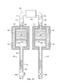
- FIG. 4 illustrates an example charging system 400
- FIGS. 5A through 5G illustrate example operations of the charging system 400 .
- This type of charging system could, for example, be implemented as the power generator 312 in the vehicle 300 of FIG. 3 , although this type of charging system could be used in any other suitable device or system.
- the charging system 400 generally employs a Carnot-Brayton cycle involving two tanks 402 and 404 .
- a refrigerant 406 is transferred back and forth between the tanks 402 and 404 through a generator 408 .
- Each tank 402 or 404 is configured to hold the refrigerant 406 under pressure and to provide the refrigerant 406 through the generator 408 to the other tank 404 or 402 .
- the generator 408 generates electrical power.
- Each tank 402 and 404 includes any suitable structure configured to hold a refrigerant under pressure.
- the refrigerant 406 includes any suitable fluid used to transfer heat between the tanks 402 and 404 , such as gaseous or liquid carbon dioxide.
- the generator 408 includes any suitable structure for generating electrical energy based on a flow of refrigerant, such as a Pelton turbine or a brushless DC (BLDC) generator.
- the generator 408 could include a vane motor, impulse, or axial flow turbine and a choked flow orifice. If implemented in this manner, different turbines could be used to generate power for refrigerant flows in different directions, with choked flow orifices on different sides of the different turbines. Alternatively, adjustable orifices could be used on opposing sides of a single turbine and opened or closed based on the direction of refrigerant flow.
- the charging system 400 can also include multiple insulated water jackets 410 and 412 .
- Each insulated water jacket 410 and 412 receives and retains warmer or colder water in order to facilitate movement of the refrigerant 406 between the tanks 402 and 404 .
- the tank 402 or 404 containing more refrigerant 406 can be surrounded by warmer water, increasing the pressure in that tank.
- the tank 404 or 402 containing less refrigerant 406 can be surrounded by colder water, lowering the pressure in that tank.
- the pressure difference can be used to facilitate easier or more effective refrigerant transport between the tanks 402 and 404 .
- Each insulated water jacket 410 and 412 includes any suitable insulated structure configured to receive and retain water.
- the insulated water jackets 410 and 412 need not be pressurized and can be unpressurized containers.
- Conduits 414 and 416 respectively couple the tanks 402 and 404 to the generator 408 .
- Each conduit 414 and 416 denotes any suitable passageway for a refrigerant.
- Each conduit 414 and 416 could be formed from any suitable material(s) and in any suitable manner. Note that while a single conduit 414 and 416 couples each tank 402 and 404 to the generator 408 , multiple conduits could also be used for each tank. For example, different conduits could be used to support refrigerant flows in different directions (and possibly coupled to different generators 408 ).
- Valves 418 and 420 are used to control the flow of the refrigerant 406 through the conduits 414 and 416 .
- the valve 418 controls whether the refrigerant 406 can enter or exit the tank 402 through the conduit 414
- the valve 420 controls whether the refrigerant 406 can enter or exit the tank 404 through the conduit 416 .
- Each valve 418 and 420 denotes any suitable structure for controlling the flow of a refrigerant, such as a needle valve.
- Additional valves 422 - 428 are included in the insulated water jackets 410 and 412 to control the flow of fresh water into and out of the insulated water jackets 410 and 412 .
- the valves 422 - 424 or 426 - 428 could be opened so that fresh warmer water can be drawn into the insulated water jacket 410 or 412 .
- the valves 422 - 424 or 426 - 428 could be opened so that fresh colder water can be drawn into the insulated water jacket 410 or 412 .
- Each valve 422 - 428 denotes any suitable structure for controlling the flow of water into or out of an insulated water jacket.
- valves 418 - 428 shown in FIG. 4 could be controlled in any suitable manner.
- the controller 302 of an underwater vehicle 300 could control the valves 418 - 428 as part of the overall control of the vehicle 300 .
- each tank 402 and 404 is associated with a hydraulic drive 430 and 432 , respectively.
- Each hydraulic drive 430 and 432 is configured to use water pressure when the vehicle 300 dives underwater to help force the refrigerant 406 out of one of the tanks 402 and 404 .
- each hydraulic drive 430 or 432 includes a piston 434 within the associated tank 402 or 404 .
- the piston 434 is sealed with sides of the associated tank so that all or substantially all of the refrigerant 406 cannot pass the piston 434 .
- Each piston 434 denotes any suitable structure for moving within a tank and pushing a refrigerant.
- Each hydraulic drive 430 or 432 also includes a channel 436 that contains a hydraulic fluid 438 and a movable piston structure 440 .
- the channel 436 is fluidly coupled to the associated tank 402 or 404 so that the hydraulic fluid 438 can move freely into and out of the tank.
- the amount of hydraulic fluid 438 forced into the associated tank 402 or 404 controls the position of the piston 434 in that tank, thereby controlling the amount of force being applied to the refrigerant 406 in that tank.
- the channel 436 denotes any suitable passageway configured to hold a hydraulic fluid.
- the hydraulic fluid 438 denotes any suitable material that can be used to apply force against a piston, such as an oil.
- the movable piston structure 440 represents a structure that moves based on external pressure in order to increase or decrease the amount of hydraulic fluid 438 within the associated tank 402 or 404 .
- the movable piston structure 440 includes two small pistons 442 a - 442 b attached by a connecting bar 444 , which helps to provide two seals between the hydraulic fluid 438 and an external environment.
- An interior space between the pistons 442 a - 442 b could contain air or fluid, such as castor oil.
- any other suitable piston(s) could be used as the piston structure 440 .
- one or more stops could be used to control the range of possible motion of the movable piston structure 440 .
- the piston structure 440 is moved using water 446 , which is allowed to enter the hydraulic drive 430 or 432 via a respective valve 448 a or 448 b .
- the water 446 can enter a channel 436 when the associated valve 448 a or 448 b is opened and the vehicle 300 is underwater at a suitable depth.
- the elevated water pressure can force the water 446 into the channel 436 , pushing the associated piston structure 440 towards the associated tank 402 or 404 and pushing more of the hydraulic fluid 438 into the associated tank 402 or 404 .
- the water 446 can exit a channel 436 when the associated valve 448 a or 448 b is opened and the vehicle 300 is at or near the surface of a water body.
- Each valve 448 a - 448 b denotes any suitable structure for controlling the flow of water into and out of a channel.
- Example operations of the charging system 400 are shown in FIGS. 5A through 5G .
- the charging system 400 has just completed a prior power generation cycle.
- Most or all of the refrigerant 406 is located in the tank 402 , and the valves 418 and 420 have been closed to prevent further transfer of refrigerant 406 .
- the valve 448 a is closed and the valve 448 b is opened, so there is more water 446 in the hydraulic drive 432 than in the hydraulic drive 430 .
- the vehicle 300 has ascended, and the valve 448 b remains opened.
- the water in the water jackets 410 and 412 can be flushed and replaced with warmer water.
- the higher ambient temperature and/or the higher temperature of the warmer water in the water jacket 412 can heat the refrigerant 406 in the tank 404 , causing the refrigerant 406 to expand and push some of the water 446 out of the hydraulic drive 432 through the valve 448 b .
- the pistons 434 in the hydraulic drives 430 and 432 could be located at substantially the same positions within the tanks 402 and 404 at this point.
- the vehicle 300 can then close the valve 448 b and dive to a desired depth, such as several hundred meters or more. Once at a desired depth, the water in the water jacket 412 can be flushed and replaced with colder water. Also, the valves 418 , 420 , and 448 a can be opened as shown in FIG. 5C .
- the temperature differential between the tanks 402 and 404 created in part by the temperature differential of the water in the water jackets 410 and 412 ) and the pressure created by the piston 434 in the tank 402 (caused by water pressure through the valve 448 a ) causes most or all of the refrigerant 406 to flow from the tank 402 into the tank 404 through the generator 408 , producing electrical power.
- the charging system 400 reaches the state that is shown in FIG. 5D , where the bulk of the refrigerant 406 has been transferred to the tank 404 and the piston 434 in the tank 402 has reached its maximum travel.
- the same process can occur with the tanks reversed.
- the vehicle 300 has ascended, and the valve 448 a remains opened.
- the water in the water jackets 410 and 412 can be flushed and replaced with warmer water.
- the higher ambient temperature and/or the higher temperature of the warmer water in the water jacket 410 can heat the refrigerant 406 in the tank 402 , causing the refrigerant 406 to expand and push some of the water 446 out of the hydraulic drive 430 through the valve 448 a .
- the pistons 434 in the hydraulic drives 430 and 432 could be located at substantially the same positions within the tanks 402 and 404 at this point.
- the vehicle 300 can then close the valve 448 a and dive to a desired depth, such as several hundred meters or more. Once at a desired depth, the water in the water jacket 410 can be flushed and replaced with colder water. Also, the valves 418 , 420 , and 448 b can be opened as shown in FIG. 5F .
- the temperature differential between the tanks 402 and 404 created in part by the temperature differential of the water in the water jackets 410 and 412
- the pressure created by the piston 434 in the tank 404 causes most or all of the refrigerant 406 to flow from the tank 404 into the tank 402 through the generator 408 , producing electrical power.
- the charging system 400 reaches the state that is shown in FIG. 5G , where the bulk of the refrigerant 406 has been transferred to the tank 402 and the piston 434 in the tank 404 has reached its maximum travel. This is the same condition shown in FIG. 5A .
- the amount of power generated during these cycles can vary based on a number of factors, such as the size of the tanks 402 and 404 , the amount of refrigerant 406 in the tanks 402 and 404 , the temperatures of the tanks 402 and 404 , and the amount of pressure applied by the pistons 434 in the tanks 402 and 404 .
- the charging system 400 could use about twenty pounds of carbon dioxide, the warmer water temperature could be about 25° C., the colder water temperature could be about 5° C., and a pressure differential of up to 500 pounds per square inch (PSI) or more could be created between the tanks 402 and 404 at a depth of 1,000 meters. Given these parameters, the charging system 400 could generate about 430 kJ of energy per dive.
- the charging system 400 generally employs a Carnot-Brayton cycle.
- the Carnot portion of the cycle uses the hydraulic pistons 434 driven by pressure at depth. Pressure at depth increases the forces applied to the refrigerant 406 by the pistons 434 in the tanks 402 and 404 , which occurs alternatively between the tanks 402 and 404 .
- the Brayton portion of the cycle involves the use of high-pressure gas expanding through a turbine, where heat is added to the gas through evaporative cooling, the gas is passed through a generator, and the gas is then cooled.
- the charging system 400 therefore provides power generation based on variable and fixed volumes.
- the use of the hydraulic drives 430 and 432 helps to provide the charging system 400 with a mechanical advantage to help pressurize the refrigerant 406 while overcoming resistance of the receiving vessel.
- the charging system 400 supports a variable volume power system that multiplies water pressures via a hydraulic mechanical advantage. For instance, an advantage of 3:1 allows 400 PSI of water pressure to be converted to 1,200 PSI of pressure by a piston 434 against the refrigerant 406 , while an advantage of 4:1 allows 400 PSI of water pressure to be converted to 1,600 PSI of pressure by a piston 434 against the refrigerant 406 .
- the mechanical advantage defined by the ratio X:1 indicates that a tank 402 or 404 is X times wider than the channel 436 of the associated hydraulic drive 430 or 432 or that the tank 402 or 404 has a cross-sectional area X times wider than a cross-sectional area of the channel 436 of the associated hydraulic drive 430 or 432 (where X is any whole or real number greater than one).
- This type of pressure can be suitable for use in gas transfer systems using carbon dioxide gas or other gaseous refrigerant 406 .
- hydraulic lines can route forces for better packaging of the charging system 400 .
- FIGS. 4 through 5G illustrate one example of a charging system 400 for periodically charging an underwater vehicle
- various changes may be made to FIGS. 4 through 5G .
- various components in each figure could be combined, further subdivided, rearranged, or omitted or additional components could be added according to particular needs.
- shapes, sizes, and dimensions of various components in these figures could vary as needed or desired.
- the use of the water jackets 410 and 412 may be optional, such as when the water pressures applied to the hydraulic drives 430 and 432 generate refrigerant flows adequate for power generation.
- FIG. 6 illustrates an example method 600 for periodically charging an underwater vehicle in accordance with this disclosure.
- the method 600 is described with respect to the charging system 400 operating in the vehicle 300 .
- the method 600 could be used in any other suitable device or system.
- pistons of the charging system are placed in substantially equal positions at a higher depth at step 602 .
- the underwater vehicle dives to a lower depth at step 604 .
- This could include, for example, the charging system 400 closing the valve 448 b .
- This could also include the controller 302 of the vehicle 300 controlling the propulsion components 318 so that the vehicle 300 dives to a desired depth, such as up to 1,000 meters or more.
- a refrigerant is caused to flow from a first tank through a generator and into a second tank at step 606 .
- This could include, for example, the charging system 400 pulling colder water into the water jacket 412 and opening the valves 418 and 420 .
- This could also include the refrigerant 406 flowing from the tank 402 to the tank 404 .
- a first valve of a first hydraulic drive is opened to drive a first piston in the first tank using water at step 608 .
- Electrical power is generated and stored and/or used at step 610 .
- the DC power can be provided to the power conditioner 314 and stored in the power storage 316 or used by the vehicle 300 .
- the transfer of the refrigerant eventually stops or is prevented, and at some point the vehicle rises to a higher depth at step 612 .
- Water is pushed out of the first hydraulic drive at step 614 .
- This could also include the warmer water or a warmer ambient temperature heating the refrigerant 406 in the tank 402 , causing the refrigerant 406 to expand and push the water 446 out of the hydraulic drive 430 through the valve 448 a .
- the process repeats with the tanks and water jackets reversed.
- the underwater vehicle dives to a lower depth at step 618 .
- the refrigerant is caused to flow from the second tank through a generator and into the first tank at step 620 .
- This could include, for example, the charging system 400 pulling colder water into the water jacket 410 and opening the valves 418 and 420 .
- This could also include the refrigerant 406 flowing from the tank 404 to the tank 402 .
- a second valve of a second hydraulic drive is opened to drive a second piston in the second tank using water at step 622 .
- This could include, for example, the charging system 400 opening the valve 448 b to allow water 446 to enter the hydraulic drive 432 .
- Electrical power is generated and stored and/or used at step 624 .
- the DC power can be provided to the power conditioner 314 and stored in the power storage 316 or used by the vehicle 300 .
- the overall process can begin again by causing the underwater vehicle to ascend to a higher depth at step 626 and pushing the water out of the second hydraulic drive at step 628 .
- This could include, for example, the charging system 400 pulling warmer water into the water jackets 410 and 412 .
- This could also include the warmer water or a warmer ambient temperature heating the refrigerant 406 in the tank 402 , causing the refrigerant 406 to expand and push the water 446 out of the channel 436 of the hydraulic drive 430 through the valve 448 b .
- This causes the pistons of the charging system to be placed in substantially equal positions at the higher depth back at step 602 .
- This process can be repeated any number of times as the vehicle 300 ascends and descends in a body of water.
- the interval of time between ascending and descending can be fixed or variable and could vary based on a number of factors.
- FIG. 6 illustrates one example of a method 600 for periodically charging an underwater vehicle
- various changes may be made to FIG. 6 .
- steps in FIG. 6 could overlap, occur in parallel, occur in a different order, or occur any number of times.
- steps 606 - 610 or steps 620 - 624 generally overlap during the production of electrical power.
- FIGS. 7A through 7C illustrate an example ballast system 700 for an underwater vehicle in accordance with this disclosure.
- This type of ballast system could, for example, be implemented as any of the ballasts 108 a - 108 b , 208 a - 208 b , although this type of ballast system could be used in any other suitable device or system.
- the ballast system 700 generally operates to pull variable amounts of water 702 into a cavity 704 .
- the cavity 704 denotes any suitable structure configured to receive and hold fluid. This could be done to adjust an underwater vehicle's center of gravity, stabilize the underwater vehicle, or perform other functions.
- a hydraulic drive 706 is used to adjust the amount of water 702 in the cavity 704 .
- the hydraulic drive 706 includes a piston 708 that is positioned within the cavity 704 and that pushes the water 702 out of and pulls the water 702 into the cavity 704 .
- the piston 708 can be sealed against the inner wall(s) of the cavity 704 .
- the piston 708 denotes any suitable structure for moving within a cavity.
- the hydraulic drive 706 also includes a channel 710 that contains a hydraulic fluid 712 and a movable piston structure 714 .
- the channel 710 is fluidly coupled to the cavity 704 so that the hydraulic fluid 712 can move into and out of the cavity 704 .
- the amount of hydraulic fluid 712 forced into the cavity 704 controls the position of the piston 708 within the cavity 704 , thereby controlling the amount of water 702 in the cavity 704 .
- the channel 710 denotes any suitable passageway configured to hold a hydraulic fluid.
- the hydraulic fluid 712 denotes any suitable material that can be used to apply force against a piston, such as an oil.
- the movable piston structure 714 represents a structure that moves in order to increase or decrease the amount of hydraulic fluid 712 within the cavity 704 .
- the movable piston structure 714 includes two small pistons 716 a - 716 b attached by a connecting bar 718 .
- An interior space between the pistons 716 a - 716 b is divided into multiple pressure volumes 720 a - 720 b by a separator 722 .
- Each pressure volume 720 a - 720 b denotes a space configured to receive a fluid (such as a gas or liquid) in order to move the piston structure 714 .
- the separator 722 denotes any suitable structure for separating a space into different volumes.
- An end portion of the channel 710 includes at least one vent 724 .
- the vent 724 allows air within the end of the channel 710 to move into and out of channel 710 as the piston structure 714 moves.
- Each vent 724 includes an opening with any suitable size and shape, and any number and arrangement of vents can be used.
- Valves 726 and 728 are fluidly coupled to the pressure volumes 720 a - 720 b and to tanks 730 and 732 .
- the tanks 730 and 732 can be used to provide fluid to or receive fluid from the pressure volumes 720 a - 720 b .
- one of the tanks 730 and 732 functions as a source while another of the tanks 732 and 730 functions as a sink. These roles could be swapped over time, such as when the tanks 730 and 732 are implemented with water jackets that can receive warmer and colder water to alter the roles of the tanks 730 and 732 .
- Each of the valves 726 and 728 includes any suitable structure for controlling a flow of fluid into and out of a pressure volume.
- Each of the tanks 730 and 732 includes any suitable structure for holding a gas or other fluid used to adjust a position of a movable piston structure.
- the tanks 730 and 732 may or may not represent the same tanks 402 and 404 used in a charging system 400 .
- the movable piston structure 714 may be located at or near its top extreme position, so the pressure volume 720 a has been expanded in size and the pressure volume 720 b has been reduced in size.
- the valves 726 and 728 have been opened, allowing fluid to flow from the tank 732 into the pressure volume 720 b .
- a colder temperature or pressure of the tank 730 or movement of the piston structure 714 pushes fluid out of the pressure volume 720 a into the tank 730 .
- the piston structure 714 moves downward.
- the position in FIG. 7B could denote a neutral buoyance position of the ballast system 700 .
- FIG. 7B could denote a neutral buoyance position of the ballast system 700 .
- the piston structure 714 may be located at or near its bottom extreme position, so the pressure volume 720 b has been expanded in size and the pressure volume 720 a has been reduced in size.
- a similar process could be repeated by pushing fluid into the pressure volume 720 a and removing fluid from the pressure volume 720 b , allowing the movable piston structure 714 to move back up. Note that the movable piston structure 714 could be controlled to stop at any desired location between its extreme positions.
- the hydraulic drive 706 is used to control the amount of material in a defined space here.
- the same type of control mechanism used above in the charging system 400 can be used in the ballast system 700 .
- the ballast system 700 therefore obtains a mechanical advantage using the hydraulic drive 706 .
- an advantage of 2:1 allows 700 PSI of pressure to be converted to 1,400 PSI of pressure by the piston 708 against the water 702
- an advantage of 3:1 allows 700 PSI of pressure to be converted to 2,100 PSI of pressure by the piston 708 against the water 702 . This allows the ballast system 700 to use smaller amounts of pressure even when a vehicle is under elevated pressure at large depths.
- the mechanical advantage defined by the ratio X:1 indicates that the cavity 704 is X times wider than the channel 710 or that the cavity 704 has a cross-sectional area X times wider than a cross-sectional area of the channel 710 (where X is any whole or real number greater than one).
- the ballast system 700 provides a variable volume buoyancy system through the use of the hydraulic drive 706 .
- the system 700 can have dual use as part of a topping cycle (with mechanical advantage) and a buoyancy system (also with mechanical advantage).
- FIGS. 7A through 7C illustrate one example of a ballast system 700 for an underwater vehicle
- various changes may be made to FIGS. 7A through 7C .
- various components in FIGS. 7A through 7C could be combined, further subdivided, rearranged, or omitted or additional components could be added according to particular needs.
- shapes, sizes, and dimensions of various components in FIGS. 7A through 7C could vary as needed or desired.
- FIG. 8 illustrates an example method 800 for stabilizing an underwater vehicle using a ballast system in accordance with this disclosure.
- the method 800 is described with respect to the ballast system 700 operating in the vehicle 300 .
- the method 800 could be used in any other suitable device or system.
- a desired change in a ballast level is identified at step 802 .
- Higher and lower pressures are created in or applied to different pressure volumes within a hydraulic drive at step 804 .
- This could include, for example, the ballast system 700 opening the valves 726 and 728 to allow fluid to flow into and out of the appropriate pressure volumes 720 a - 720 b .
- This causes a hydraulic piston to change position within a cavity of a hydraulic drive at step 806 .
- This could include, for example, the changes in pressure within the pressure volumes 720 a - 720 b causing the movable piston structure 714 to move.
- This alters an amount of hydraulic fluid within the cavity at step 808 , moves a ballast piston within the cavity at step 810 , and alters an amount of ballast within the cavity at step 812 .
- This could include, for example, the movable piston structure 714 altering an amount of the hydraulic fluid 712 within the cavity 704 , moving the piston 708 within the cavity 704 and changing an amount of water 702 within the cavity 704 .
- FIG. 8 illustrates one example of a method 800 for stabilizing an underwater vehicle using a ballast system
- various changes may be made to FIG. 8 .
- steps in FIG. 8 could overlap, occur in parallel, occur in a different order, or occur any number of times.
- steps 804 - 812 generally overlap with one another.
- various functions described in this patent document are implemented or supported by a computer program that is formed from computer readable program code and that is embodied in a computer readable medium.
- computer readable program code includes any type of computer code, including source code, object code, and executable code.
- computer readable medium includes any type of medium capable of being accessed by a computer, such as read only memory (ROM), random access memory (RAM), a hard disk drive, a compact disc (CD), a digital video disc (DVD), or any other type of memory.
- ROM read only memory
- RAM random access memory
- CD compact disc
- DVD digital video disc
- a “non-transitory” computer readable medium excludes wired, wireless, optical, or other communication links that transport transitory electrical or other signals.
- a non-transitory computer readable medium includes media where data can be permanently stored and media where data can be stored and later overwritten, such as a rewritable optical disc or an erasable memory device.
- application and “program” refer to one or more computer programs, software components, sets of instructions, procedures, functions, objects, classes, instances, related data, or a portion thereof adapted for implementation in a suitable computer code (including source code, object code, or executable code).
- program refers to one or more computer programs, software components, sets of instructions, procedures, functions, objects, classes, instances, related data, or a portion thereof adapted for implementation in a suitable computer code (including source code, object code, or executable code).
- communicate as well as derivatives thereof, encompasses both direct and indirect communication.
- the term “or” is inclusive, meaning and/or.
- phrases “associated with,” as well as derivatives thereof, may mean to include, be included within, interconnect with, contain, be contained within, connect to or with, couple to or with, be communicable with, cooperate with, interleave, juxtapose, be proximate to, be bound to or with, have, have a property of, have a relationship to or with, or the like.
- the phrase “at least one of,” when used with a list of items, means that different combinations of one or more of the listed items may be used, and only one item in the list may be needed. For example, “at least one of: A, B, and C” includes any of the following combinations: A, B, C, A and B, A and C, B and C, and A and B and C.
Landscapes
- Engineering & Computer Science (AREA)
- Mechanical Engineering (AREA)
- Chemical & Material Sciences (AREA)
- Combustion & Propulsion (AREA)
- Aviation & Aerospace Engineering (AREA)
- General Engineering & Computer Science (AREA)
- Ocean & Marine Engineering (AREA)
- Chemical Kinetics & Catalysis (AREA)
- Other Liquid Machine Or Engine Such As Wave Power Use (AREA)
- Charge And Discharge Circuits For Batteries Or The Like (AREA)
Priority Applications (2)
| Application Number | Priority Date | Filing Date | Title |
|---|---|---|---|
| US15/173,214 US9834288B1 (en) | 2016-06-03 | 2016-06-03 | Hydraulic drives for use in charging systems, ballast systems, or other systems of underwater vehicles |
| PCT/US2017/016976 WO2017209806A2 (fr) | 2016-06-03 | 2017-02-08 | Entraînements hydrauliques destinés à être utilisés dans des systèmes de charge, des systèmes de ballast ou d'autres systèmes de véhicules sous-marins |
Applications Claiming Priority (1)
| Application Number | Priority Date | Filing Date | Title |
|---|---|---|---|
| US15/173,214 US9834288B1 (en) | 2016-06-03 | 2016-06-03 | Hydraulic drives for use in charging systems, ballast systems, or other systems of underwater vehicles |
Publications (2)
| Publication Number | Publication Date |
|---|---|
| US9834288B1 true US9834288B1 (en) | 2017-12-05 |
| US20170349252A1 US20170349252A1 (en) | 2017-12-07 |
Family
ID=58046786
Family Applications (1)
| Application Number | Title | Priority Date | Filing Date |
|---|---|---|---|
| US15/173,214 Active US9834288B1 (en) | 2016-06-03 | 2016-06-03 | Hydraulic drives for use in charging systems, ballast systems, or other systems of underwater vehicles |
Country Status (2)
| Country | Link |
|---|---|
| US (1) | US9834288B1 (fr) |
| WO (1) | WO2017209806A2 (fr) |
Cited By (8)
| Publication number | Priority date | Publication date | Assignee | Title |
|---|---|---|---|---|
| US20170350558A1 (en) * | 2016-06-03 | 2017-12-07 | Raytheon Company | Apparatus and method for periodically charging ocean vessel or other system using thermal energy conversion |
| US10502099B2 (en) | 2017-01-23 | 2019-12-10 | Raytheon Company | System and method for free-piston power generation based on thermal differences |
| US10946944B2 (en) | 2016-04-05 | 2021-03-16 | Raytheon Company | Modified CO2 cycle for long endurance unmanned underwater vehicles and resultant chirp acoustic capability |
| US11001357B2 (en) | 2019-07-02 | 2021-05-11 | Raytheon Company | Tactical maneuvering ocean thermal energy conversion buoy for ocean activity surveillance |
| WO2021139846A1 (fr) * | 2020-01-10 | 2021-07-15 | Zhenhua Xi | Procédé de liquéfaction et de stockage de co2 dans une centrale au co2 |
| US11085425B2 (en) | 2019-06-25 | 2021-08-10 | Raytheon Company | Power generation systems based on thermal differences using slow-motion high-force energy conversion |
| CN116767470A (zh) * | 2023-07-24 | 2023-09-19 | 哈尔滨工程大学 | 一种应用于水下航行体的双模式能源供应系统 |
| WO2023199073A1 (fr) * | 2022-04-14 | 2023-10-19 | Italmatch Chemicals Gb Limited | Appareil pour lever ou abaisser une charge dans une masse d'eau |
Citations (41)
| Publication number | Priority date | Publication date | Assignee | Title |
|---|---|---|---|---|
| US952452A (en) | 1908-08-25 | 1910-03-22 | Karl Oskar Leon | Automatic depth-regulating device for freely-subfloating bodies. |
| US1315267A (en) | 1919-09-09 | Morkis columbus white | ||
| US1361561A (en) | 1918-11-02 | 1920-12-07 | Yancey William Oscar | Toy submarine |
| US1421369A (en) | 1922-07-04 | Submersible flying boat | ||
| GB235363A (en) | 1924-05-07 | 1925-06-18 | Percy James Hammond Sumner | Improvements in submarine vessels |
| US1710670A (en) | 1929-04-23 | Tttbix of said leonard w | ||
| US2000746A (en) | 1934-04-21 | 1935-05-07 | Dray Michael | Automatic submarine safety apparatus |
| GB541775A (en) | 1938-08-08 | 1941-12-11 | Brev Moineau S A R L Soc D Exp | Improvements in devices for the propulsion of watercraft |
| US2381478A (en) | 1942-09-10 | 1945-08-07 | Zukor Arnold | Automatic airplane safety raising and guiding device |
| US2537929A (en) | 1945-10-29 | 1951-01-09 | Thomas A Daly | Timer |
| GB658070A (en) | 1949-08-03 | 1951-10-03 | Harold Ernest Flory | Improvements in or relating to toy submarines |
| US2642693A (en) | 1947-07-22 | 1953-06-23 | Francis V Broady | Apparatus for retrieving fishing tackle or the like |
| US2720367A (en) | 1951-10-15 | 1955-10-11 | All American Eng Co | Method of maneuvering combination submarine and aircraft |
| US2750794A (en) | 1952-11-07 | 1956-06-19 | George W Downs | Acoustisonde apparatus for measuring and recording physical properties of the sea |
| US2783955A (en) | 1952-05-02 | 1957-03-05 | Patrick James L G Fitz | Air, land, and water craft |
| US2823636A (en) | 1955-02-13 | 1958-02-18 | Aerojet General Co | Vessel |
| US2826001A (en) | 1956-05-11 | 1958-03-11 | Frank G Presnell | Self-propelled model submarine |
| US2845221A (en) | 1953-09-11 | 1958-07-29 | Allyn C Vine | Buoyancy recorder |
| US2964874A (en) | 1959-08-25 | 1960-12-20 | Ruiz Armando | Submersible toy |
| US3157145A (en) | 1960-12-07 | 1964-11-17 | Oceanic Systems Corp | Underwater glider |
| US3698345A (en) * | 1970-12-28 | 1972-10-17 | Sperry Rand Corp | Active tank stabilizer for marine vessels |
| US3818523A (en) | 1971-10-18 | 1974-06-25 | Sanders Associates Inc | Subsurface current utilizing buoy system |
| US4445818A (en) * | 1981-03-13 | 1984-05-01 | Jidosha Kiki Co., Ltd. | Apparatus for supplying hydraulic fluid |
| US4577583A (en) | 1984-06-28 | 1986-03-25 | Green Ii John G | Small gliding underwater craft |
| US4850551A (en) | 1987-12-14 | 1989-07-25 | Lockheed Corporation | Propulsion system for a buoyant vehicle |
| US4919637A (en) | 1986-05-22 | 1990-04-24 | Leonard Bloom | Model submarine |
| US5134955A (en) | 1988-08-31 | 1992-08-04 | Manfield Harold D | Submergible diving sled |
| US5291847A (en) | 1991-08-01 | 1994-03-08 | Webb Douglas C | Autonomous propulsion within a volume of fluid |
| US5303552A (en) | 1992-07-06 | 1994-04-19 | Webb Douglas C | Compressed gas buoyancy generator powered by temperature differences in a fluid body |
| US5615632A (en) | 1996-02-07 | 1997-04-01 | The United States Of America As Represented By The Secretary Of The Navy | Underwater vehicle and a fin assembly therefor |
| US6263819B1 (en) | 1999-09-16 | 2001-07-24 | Pacific Marine Supply Co., Ltd. | Low drag submerged displacement hull |
| US6328622B1 (en) | 1996-10-07 | 2001-12-11 | Daniel J Geery | Submersible water toy |
| GB2422877A (en) | 2005-02-04 | 2006-08-09 | Duncan James Parfitt | Piston-and-cylinder machine, eg for generating electricity, using the vacuum created by condensing vapour |
| US20070186553A1 (en) | 2006-02-15 | 2007-08-16 | Lin Hsing-Fa | Thermo-driven engine |
| US20080088171A1 (en) * | 2006-10-05 | 2008-04-17 | Shang-I Cheng | Mining methane, sequestering carbon dioxide and farming in oceans |
| US20100327605A1 (en) | 2009-06-26 | 2010-12-30 | Larry Andrews | Power Generation Systems, Processes for Generating Energy at an Industrial Mine Site, Water Heating Systems, and Processes of Heating Water |
| WO2011000062A1 (fr) | 2009-07-02 | 2011-01-06 | Tsekov Nikola Petrov | Procédé et dispositif pour moteur thermohydraulique pour convertir l'énergie thermique en énergie mécanique |
| US20110101579A1 (en) * | 2009-10-30 | 2011-05-05 | Great Lakes Sound & Vibration, Inc. | Multi-Stage Telescopic Shock Absorber |
| US20120091942A1 (en) | 2010-10-14 | 2012-04-19 | Jones Jack A | Submerged charging station |
| EP2660433A1 (fr) | 2012-05-02 | 2013-11-06 | E-Mind Studi e Progettazione Ing. Vitri Giuseppe e Ing. Luchetti Filippo | Dispositif et procédé de production d'énergie électrique |
| EP2698506A1 (fr) | 2012-08-17 | 2014-02-19 | ABB Research Ltd. | Système de stockage d'énergie électrothermique et procédé pour stocker de l'énergie électrothermique |
Family Cites Families (6)
| Publication number | Priority date | Publication date | Assignee | Title |
|---|---|---|---|---|
| DE215277C (fr) * | 1906-12-22 | 1906-12-22 | ||
| US6142092A (en) * | 1997-06-13 | 2000-11-07 | The Secretary Of State For Defence In Her Britannic Majesty's Government Of The United Kingdom Of Great Britain And Northern Ireland | Depth control device |
| US7921795B2 (en) * | 2007-12-27 | 2011-04-12 | Alaska Native Technologies, Llc | Buoyancy control systems and methods |
| US8069808B1 (en) * | 2007-12-27 | 2011-12-06 | Alaska Native Technologies, Llc | Buoyancy control systems and methods for submersible objects |
| US8205570B1 (en) * | 2010-02-01 | 2012-06-26 | Vehicle Control Technologies, Inc. | Autonomous unmanned underwater vehicle with buoyancy engine |
| US20120289103A1 (en) * | 2010-09-24 | 2012-11-15 | Edison Thurman Hudson | Unmanned Underwater Vehicle |
-
2016
- 2016-06-03 US US15/173,214 patent/US9834288B1/en active Active
-
2017
- 2017-02-08 WO PCT/US2017/016976 patent/WO2017209806A2/fr active Application Filing
Patent Citations (41)
| Publication number | Priority date | Publication date | Assignee | Title |
|---|---|---|---|---|
| US1315267A (en) | 1919-09-09 | Morkis columbus white | ||
| US1421369A (en) | 1922-07-04 | Submersible flying boat | ||
| US1710670A (en) | 1929-04-23 | Tttbix of said leonard w | ||
| US952452A (en) | 1908-08-25 | 1910-03-22 | Karl Oskar Leon | Automatic depth-regulating device for freely-subfloating bodies. |
| US1361561A (en) | 1918-11-02 | 1920-12-07 | Yancey William Oscar | Toy submarine |
| GB235363A (en) | 1924-05-07 | 1925-06-18 | Percy James Hammond Sumner | Improvements in submarine vessels |
| US2000746A (en) | 1934-04-21 | 1935-05-07 | Dray Michael | Automatic submarine safety apparatus |
| GB541775A (en) | 1938-08-08 | 1941-12-11 | Brev Moineau S A R L Soc D Exp | Improvements in devices for the propulsion of watercraft |
| US2381478A (en) | 1942-09-10 | 1945-08-07 | Zukor Arnold | Automatic airplane safety raising and guiding device |
| US2537929A (en) | 1945-10-29 | 1951-01-09 | Thomas A Daly | Timer |
| US2642693A (en) | 1947-07-22 | 1953-06-23 | Francis V Broady | Apparatus for retrieving fishing tackle or the like |
| GB658070A (en) | 1949-08-03 | 1951-10-03 | Harold Ernest Flory | Improvements in or relating to toy submarines |
| US2720367A (en) | 1951-10-15 | 1955-10-11 | All American Eng Co | Method of maneuvering combination submarine and aircraft |
| US2783955A (en) | 1952-05-02 | 1957-03-05 | Patrick James L G Fitz | Air, land, and water craft |
| US2750794A (en) | 1952-11-07 | 1956-06-19 | George W Downs | Acoustisonde apparatus for measuring and recording physical properties of the sea |
| US2845221A (en) | 1953-09-11 | 1958-07-29 | Allyn C Vine | Buoyancy recorder |
| US2823636A (en) | 1955-02-13 | 1958-02-18 | Aerojet General Co | Vessel |
| US2826001A (en) | 1956-05-11 | 1958-03-11 | Frank G Presnell | Self-propelled model submarine |
| US2964874A (en) | 1959-08-25 | 1960-12-20 | Ruiz Armando | Submersible toy |
| US3157145A (en) | 1960-12-07 | 1964-11-17 | Oceanic Systems Corp | Underwater glider |
| US3698345A (en) * | 1970-12-28 | 1972-10-17 | Sperry Rand Corp | Active tank stabilizer for marine vessels |
| US3818523A (en) | 1971-10-18 | 1974-06-25 | Sanders Associates Inc | Subsurface current utilizing buoy system |
| US4445818A (en) * | 1981-03-13 | 1984-05-01 | Jidosha Kiki Co., Ltd. | Apparatus for supplying hydraulic fluid |
| US4577583A (en) | 1984-06-28 | 1986-03-25 | Green Ii John G | Small gliding underwater craft |
| US4919637A (en) | 1986-05-22 | 1990-04-24 | Leonard Bloom | Model submarine |
| US4850551A (en) | 1987-12-14 | 1989-07-25 | Lockheed Corporation | Propulsion system for a buoyant vehicle |
| US5134955A (en) | 1988-08-31 | 1992-08-04 | Manfield Harold D | Submergible diving sled |
| US5291847A (en) | 1991-08-01 | 1994-03-08 | Webb Douglas C | Autonomous propulsion within a volume of fluid |
| US5303552A (en) | 1992-07-06 | 1994-04-19 | Webb Douglas C | Compressed gas buoyancy generator powered by temperature differences in a fluid body |
| US5615632A (en) | 1996-02-07 | 1997-04-01 | The United States Of America As Represented By The Secretary Of The Navy | Underwater vehicle and a fin assembly therefor |
| US6328622B1 (en) | 1996-10-07 | 2001-12-11 | Daniel J Geery | Submersible water toy |
| US6263819B1 (en) | 1999-09-16 | 2001-07-24 | Pacific Marine Supply Co., Ltd. | Low drag submerged displacement hull |
| GB2422877A (en) | 2005-02-04 | 2006-08-09 | Duncan James Parfitt | Piston-and-cylinder machine, eg for generating electricity, using the vacuum created by condensing vapour |
| US20070186553A1 (en) | 2006-02-15 | 2007-08-16 | Lin Hsing-Fa | Thermo-driven engine |
| US20080088171A1 (en) * | 2006-10-05 | 2008-04-17 | Shang-I Cheng | Mining methane, sequestering carbon dioxide and farming in oceans |
| US20100327605A1 (en) | 2009-06-26 | 2010-12-30 | Larry Andrews | Power Generation Systems, Processes for Generating Energy at an Industrial Mine Site, Water Heating Systems, and Processes of Heating Water |
| WO2011000062A1 (fr) | 2009-07-02 | 2011-01-06 | Tsekov Nikola Petrov | Procédé et dispositif pour moteur thermohydraulique pour convertir l'énergie thermique en énergie mécanique |
| US20110101579A1 (en) * | 2009-10-30 | 2011-05-05 | Great Lakes Sound & Vibration, Inc. | Multi-Stage Telescopic Shock Absorber |
| US20120091942A1 (en) | 2010-10-14 | 2012-04-19 | Jones Jack A | Submerged charging station |
| EP2660433A1 (fr) | 2012-05-02 | 2013-11-06 | E-Mind Studi e Progettazione Ing. Vitri Giuseppe e Ing. Luchetti Filippo | Dispositif et procédé de production d'énergie électrique |
| EP2698506A1 (fr) | 2012-08-17 | 2014-02-19 | ABB Research Ltd. | Système de stockage d'énergie électrothermique et procédé pour stocker de l'énergie électrothermique |
Non-Patent Citations (23)
| Title |
|---|
| Bowen, Andrew D., et al., "The Nereus Hybrid Underwater Robotic Vehicle for Global Ocean Science Operations to 11,000m Depth," 2008, 10 pages, publisher IEEE, Piscataway, New Jersey. |
| Bowen, M.F., "A Passive Capture Latch for Odyssey-Class AUVs," Technical Report WHOI-98-12, Jun. 12, 1998, 91 pages, publisher Woods Hole Oceanographic Institution, Woods Hole, MA. |
| Cowen, Steve, "Flying Plug: A Small UUV Designed for Submarine Data Connectivity (U)," Abstract, 1997, 21 pages, publisher PN. |
| Foreign Communication from Related Counterpart Application, PCT Application No. PCT/US2016/062518, International Search Report and the Written Opinion of the International Searching Authority dated May 18, 2017, 12 pages. |
| Galletti Di Cadilhac, Robin, "Docketing System," 2003, pp. 93-108, publisher Taylor & Franscis, New York, NY. |
| Gish, Lynn Andrew, "Design of an AUV Recharging System," 2004, 134 pages, publisher Massachusetts Institute of Technology, Cambridge, Massachusetts. |
| Gregory W. Heinen et al., "Apparatus and Method for Periodically Charging Ocean Vessel or Other System Using Thermal Energy Conversion", U.S. Appl. No. 15/173,178, filed Jun. 3, 2016. |
| Gregory W. Heinen, "Modified CO2 Cycle for Long Endurance Unmanned Underwater Vehicles and Resultant Chirp Acoustic Capability", U.S. Appl. No. 15/091,415, filed Apr. 5, 2016. |
| Gregory W. Heinen, et al., "Systems and Methods Supporting Periodic Exchange of Power Supplies in Uderwater Vehicles or Other Devices," U.S. Appl. No. 15/264,399, filed Sep. 13, 2016. |
| Griffiths, Gwyn, "Technology and Applications of Autonomous Underwater Vehicles," 2003, pp. 93-108, publisher Taylor & Franscis, New York, NY. |
| Hardy, Tim, et al., "Unmanned Underwater Vehicle (UUV) deployment and retrieval considerations for submarines," Paper on UUV Development and Retrieval Options for Submarines, Apr. 2008, pp. 1-15, publisher BMT Defense Services Ltd., Bath, United Kingdom. |
| Jack A. Jones et al., "Novel Thermal Powered Technology for UUV Persistant Surveillance", California Institute of Technology, Feb. 10, 2006, 11 pages. |
| Mosca, et al.; "Low-Frequency Acoustic Source for AUV Long-Range Communication"; iXSea, France; JAMSTEC, Japan, Jul. 2013, 9 pages. |
| NASA,"Utilizing Ocean Thermal Energy in a Submarine Robot", NASA's Jet Propulsion Laboratory, NASA Tech Briefs NPO-43304, Dec. 18, 2008, 4 pages. |
| Notification of Transmittal of the International Search Report and the Written Opinion of the International Searching Authority, or the Declaration dated May 29, 2017 in connection with International Patent Application No. PCT/US2017/017499. |
| Singh, Hanumant, et al., "AOSN MURI: Docketing for an Autonomous Ocean Sampling Network," Program #: ONR-322 OM/AOSN N00014-95-1-13166, 1998, 6 pages, available at http://www.whoi.edu/DSL/hanu/. |
| Singh, Hanumant, et al., "Docketing for an Autonomous Ocean Sampling Network," IEEE Journal of Oceanic Engineering, Oct. 2001, pp. 498-514, vol. 26, No. 4, publisher IEEE, Piscataway, New Jersey. |
| T. Shimura et al., "Long-Range Time Reversal Communication in Deep Water: Experimental Results", J. Acoust. Soc. Am. 132 (1), Jul. 2012, [http://dx.doi.org/10.1121/1.4730038], Jun. 19, 2012, 5 pages. |
| Terry Huntsberger et al., "Advanced Energy Storage System for Thermal Engines", California Institute of Technology, Jan. 31, 2013, 16 pages. |
| Terry Huntsberger et al., "Slocum-TREC Thermal Glider", California Institute of Technology, Jan. 31, 2012, 16 pages. |
| U.S. Appl. No. 11/081,092, filed Aug. 25, 1914, Gustav M. LaGergren. |
| Vandenberg, Troy D., "Manning and Maintainability of a Submarine Unmanned Undersea Vehicle (UUV) Program: A Systems Engineering Case Study," Thesis, Sep. 2010, 137 pages, publisher Naval Postgraduate School, Monterey, California. |
| Yi Chao, "Diurnal Variability Part I: Global 1-km SST (G1SST) Part II:GHRSST-DV-Argo Obs. System", California Institute of Technology, Feb. 28, 2011, 19 pages. |
Cited By (12)
| Publication number | Priority date | Publication date | Assignee | Title |
|---|---|---|---|---|
| US10946944B2 (en) | 2016-04-05 | 2021-03-16 | Raytheon Company | Modified CO2 cycle for long endurance unmanned underwater vehicles and resultant chirp acoustic capability |
| US20170350558A1 (en) * | 2016-06-03 | 2017-12-07 | Raytheon Company | Apparatus and method for periodically charging ocean vessel or other system using thermal energy conversion |
| US10036510B2 (en) * | 2016-06-03 | 2018-07-31 | Raytheon Company | Apparatus and method for periodically charging ocean vessel or other system using thermal energy conversion |
| US10502099B2 (en) | 2017-01-23 | 2019-12-10 | Raytheon Company | System and method for free-piston power generation based on thermal differences |
| US11085425B2 (en) | 2019-06-25 | 2021-08-10 | Raytheon Company | Power generation systems based on thermal differences using slow-motion high-force energy conversion |
| US11001357B2 (en) | 2019-07-02 | 2021-05-11 | Raytheon Company | Tactical maneuvering ocean thermal energy conversion buoy for ocean activity surveillance |
| WO2021139846A1 (fr) * | 2020-01-10 | 2021-07-15 | Zhenhua Xi | Procédé de liquéfaction et de stockage de co2 dans une centrale au co2 |
| CN114555915A (zh) * | 2020-01-10 | 2022-05-27 | 奚振华 | 二氧化碳发电厂中的二氧化碳液化和储存方法 |
| CN114555915B (zh) * | 2020-01-10 | 2024-04-12 | 奚振华 | 二氧化碳发电厂中的二氧化碳液化和储存方法 |
| WO2023199073A1 (fr) * | 2022-04-14 | 2023-10-19 | Italmatch Chemicals Gb Limited | Appareil pour lever ou abaisser une charge dans une masse d'eau |
| CN116767470A (zh) * | 2023-07-24 | 2023-09-19 | 哈尔滨工程大学 | 一种应用于水下航行体的双模式能源供应系统 |
| CN116767470B (zh) * | 2023-07-24 | 2024-01-16 | 哈尔滨工程大学 | 一种应用于水下航行体的双模式能源供应系统 |
Also Published As
| Publication number | Publication date |
|---|---|
| US20170349252A1 (en) | 2017-12-07 |
| WO2017209806A3 (fr) | 2018-03-15 |
| WO2017209806A2 (fr) | 2017-12-07 |
Similar Documents
| Publication | Publication Date | Title |
|---|---|---|
| US9834288B1 (en) | Hydraulic drives for use in charging systems, ballast systems, or other systems of underwater vehicles | |
| US10036510B2 (en) | Apparatus and method for periodically charging ocean vessel or other system using thermal energy conversion | |
| US10502099B2 (en) | System and method for free-piston power generation based on thermal differences | |
| Wang et al. | Ocean thermal energy application technologies for unmanned underwater vehicles: A comprehensive review | |
| US20120091942A1 (en) | Submerged charging station | |
| US10472034B1 (en) | Hybrid energy harvesting system for thermal-powered underwater vehicle | |
| JP6865764B2 (ja) | 長航続時間無人潜水機用の改良co2サイクル、及びそれにより得られるチャープ音響機能 | |
| WO2008140962A1 (fr) | Générateur thermique de matériau à changement de phase | |
| KR102605462B1 (ko) | 수중 에너지 하베스팅 드론 및 작동을 위한 방법 | |
| US10443581B2 (en) | Environmental thermal energy conversion | |
| US20160047362A1 (en) | Phase Change Device for Use within a Volume of Fluid | |
| US20180072168A1 (en) | Systems and methods supporting periodic exchange of power supplies in uderwater vehicles or other devices | |
| CN111661288A (zh) | 一种用于水下航行器的温差能、电能浮力驱动系统及基于该系统的航行器驱动方法 | |
| US11052981B2 (en) | Systems and methods for augmenting power generation based on thermal energy conversion using solar or radiated thermal energy | |
| US20030192310A1 (en) | Buoyant-orbicular-seesaw-system (boss) | |
| US10472033B2 (en) | Systems and methods for power generation based on surface air-to-water thermal differences | |
| AU2020299129B2 (en) | Tactical maneuvering ocean thermal energy conversion buoy for ocean activity surveillance | |
| AU2020305724B2 (en) | Power generation systems based on thermal differences using slow-motion high-force energy conversion | |
| CN118224058B (zh) | 一种高效集成式温差能驱动深海探测装置及其工作方法 | |
| Zeng et al. | Design, fabrication, and characterization of a multimodal hybrid aerial underwater vehicle |
Legal Events
| Date | Code | Title | Description |
|---|---|---|---|
| AS | Assignment |
Owner name: RAYTHEON COMPANY, MASSACHUSETTS Free format text: ASSIGNMENT OF ASSIGNORS INTEREST;ASSIGNOR:HEINEN, GREGORY W.;REEL/FRAME:038803/0617 Effective date: 20160602 |
|
| STCF | Information on status: patent grant |
Free format text: PATENTED CASE |
|
| MAFP | Maintenance fee payment |
Free format text: PAYMENT OF MAINTENANCE FEE, 4TH YEAR, LARGE ENTITY (ORIGINAL EVENT CODE: M1551); ENTITY STATUS OF PATENT OWNER: LARGE ENTITY Year of fee payment: 4 |