US9831745B2 - Electric machine - Google Patents
Electric machine Download PDFInfo
- Publication number
- US9831745B2 US9831745B2 US14/135,977 US201314135977A US9831745B2 US 9831745 B2 US9831745 B2 US 9831745B2 US 201314135977 A US201314135977 A US 201314135977A US 9831745 B2 US9831745 B2 US 9831745B2
- Authority
- US
- United States
- Prior art keywords
- air
- distributing
- electric machine
- housing
- rotor
- Prior art date
- Legal status (The legal status is an assumption and is not a legal conclusion. Google has not performed a legal analysis and makes no representation as to the accuracy of the status listed.)
- Expired - Fee Related, expires
Links
Images


Classifications
-
- H—ELECTRICITY
- H02—GENERATION; CONVERSION OR DISTRIBUTION OF ELECTRIC POWER
- H02K—DYNAMO-ELECTRIC MACHINES
- H02K9/00—Arrangements for cooling or ventilating
- H02K9/02—Arrangements for cooling or ventilating by ambient air flowing through the machine
-
- H—ELECTRICITY
- H02—GENERATION; CONVERSION OR DISTRIBUTION OF ELECTRIC POWER
- H02K—DYNAMO-ELECTRIC MACHINES
- H02K5/00—Casings; Enclosures; Supports
- H02K5/04—Casings or enclosures characterised by the shape, form or construction thereof
- H02K5/20—Casings or enclosures characterised by the shape, form or construction thereof with channels or ducts for flow of cooling medium
- H02K5/207—Casings or enclosures characterised by the shape, form or construction thereof with channels or ducts for flow of cooling medium with openings in the casing specially adapted for ambient air
-
- H—ELECTRICITY
- H02—GENERATION; CONVERSION OR DISTRIBUTION OF ELECTRIC POWER
- H02K—DYNAMO-ELECTRIC MACHINES
- H02K5/00—Casings; Enclosures; Supports
- H02K5/04—Casings or enclosures characterised by the shape, form or construction thereof
- H02K5/20—Casings or enclosures characterised by the shape, form or construction thereof with channels or ducts for flow of cooling medium
- H02K5/203—Casings or enclosures characterised by the shape, form or construction thereof with channels or ducts for flow of cooling medium specially adapted for liquids, e.g. cooling jackets
-
- H—ELECTRICITY
- H02—GENERATION; CONVERSION OR DISTRIBUTION OF ELECTRIC POWER
- H02K—DYNAMO-ELECTRIC MACHINES
- H02K9/00—Arrangements for cooling or ventilating
- H02K9/02—Arrangements for cooling or ventilating by ambient air flowing through the machine
- H02K9/04—Arrangements for cooling or ventilating by ambient air flowing through the machine having means for generating a flow of cooling medium
- H02K9/06—Arrangements for cooling or ventilating by ambient air flowing through the machine having means for generating a flow of cooling medium with fans or impellers driven by the machine shaft
-
- H—ELECTRICITY
- H02—GENERATION; CONVERSION OR DISTRIBUTION OF ELECTRIC POWER
- H02K—DYNAMO-ELECTRIC MACHINES
- H02K9/00—Arrangements for cooling or ventilating
- H02K9/19—Arrangements for cooling or ventilating for machines with closed casing and closed-circuit cooling using a liquid cooling medium, e.g. oil
- H02K9/197—Arrangements for cooling or ventilating for machines with closed casing and closed-circuit cooling using a liquid cooling medium, e.g. oil in which the rotor or stator space is fluid-tight, e.g. to provide for different cooling media for rotor and stator
Definitions
- the invention relates to an electric machine that is supplied with air for cooling purposes.
- the electric machine has a housing with cooling ducts for the cooling air.
- the invention also relates to a motor vehicle with an electric machine of this type.
- US Patent Application Pub. No. 2011/0127862 discloses an electric machine with a housing that has two end surfaces and a housing interior between the end surfaces.
- the housing has a lateral area that radially bounds the housing interior.
- a laminated rotor core has axially running cooling ducts and radially running cooling ducts.
- the radially running cooling ducts of the laminated rotor core are open radially outward and extend radially inward at least as far as the axially running cooling ducts.
- Axial ribs bear a laminated stator core that interacts electrically with the laminated rotor core.
- the laminated rotor core has radially running cooling ducts that are open radially inward and radially outward and interact with the radially running cooling ducts of the laminated rotor core.
- German laid-open application DE 195 46 040 A1 discloses a power regulation system for an electric motor with a plate. At least one electronic component is disposed on a first surface of the plate and cooling ribs are on the second surface of the plate. An air stream can flow around the cooling ribs.
- the cooling ribs define an inlet strand to which the air stream can be supplied, and two outlet strands. The outlet strands are connected to the inlet strand and divert the air stream so that the air stream circulates tangentially with respect to the plate along a Y-shaped section.
- the invention relates to an electric machine that is supplied with air for cooling.
- the electric machine has a housing with cooling ducts for cooling air. Air-distributing ducts are formed in the housing and emerge from a common air supply duct. A volumetric flow of cooling air is supplied to the electric machine via the common air supply duct. The cooling air is distributed and conducted into the housing interior via the air-distributing ducts.
- the air supply duct preferably has an oval air supply cross section.
- the air supply cross section is substantially in the form of an ellipse with a main axis arranged essentially in a radial direction.
- the term radially refers to an axis of rotation of the rotor of the electric machine. Radially indicates transversely with respect to the axis of rotation of the rotor.
- the air supply duct extends substantially in a circumferential direction.
- the term circumferential direction likewise refers to the axis of rotation of the rotor.
- the air supply duct is substantially in the form of an arc of a circle.
- the air-distributing ducts preferably lead into air-distributing pockets. Cooling air passes out of the air supply duct into a multiplicity of air-distributing pockets via the air-distributing ducts. Each air-distributing pocket may be assigned an air-distributing duct.
- the air-distributing pockets preferably are recessed in an inner base surface of the cup-like housing.
- the air-distributing pockets can be produced by primary forming, for example by inserting cores into a casting tool.
- a first axial end surface of the rotor preferably faces the air-distributing pockets for optimally providing the rotor with cooling air.
- a second axial end surface of the rotor preferably is connected to a fan wheel for conjoint rotation.
- the fan wheel advantageously is designed and arranged in so that the air supplied via the air-distributing pockets flows along the rotor from the first axial end surface of the rotor to the second axial end surface of the rotor.
- Air-removing ducts preferably are arranged in the region of the fan wheel.
- the cooling air advantageously is removed via the fan wheel.
- the air-removing ducts preferably extend radially outward. Thus, the cooling air can emerge radially to the outside virtually without obstruction.
- the invention also relates to a motor vehicle with an above-described electric machine.
- the motor vehicle is, for example, an electric vehicle or a hybrid vehicle, in which the electric machine can be used for driving the motor vehicle.
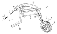
- FIG. 1 is a simplified perspective illustration of a motor vehicle with an electric machine that is supplied with air for cooling purposes.
- FIG. 2 is an enlarged, rotated illustration of the electric machine of FIG. 1 .
- FIG. 3 is a perspective sectional illustration of the electric machine of FIG. 1 .
- FIGS. 4 to 6 show similar illustrations of the electric machine from FIG. 2 with different air supply devices.
- FIG. 7 is an enlarged detail from FIG. 3 .
- FIG. 8 is a perspective illustration of a housing of the electric machine.
- FIG. 1 perspectively illustrates a cooling device 1 for cooling an electric machine 5 with cooling air.
- the cooling air is supplied to the electric machine 5 via an air inlet 6 .
- the cooling air is heated during operation of the electric machine 5 .
- the heated cooling air emerges from the electric machine at an air outlet 8 .
- the electric machine 5 is advantageously equipped with a rotating fan wheel, with the aid of which the cooling air can be sucked up via the air inlet 6 .
- An arrow 11 indicates a direction of travel of a motor vehicle 22 equipped with the cooling device 1 .
- Relative wind which is supplied in the form of an air flow 15 to the air inlet 6 is indicated by a further arrow 12 .
- the air flow 15 passes through an air inlet opening 18 , which is provided in or on a bodywork part 20 of the motor vehicle 22 , into an air box 24 .
- the air flow passes out of the air box 24 via a clean air shell 25 and a cooling-air connection 26 to the air inlet 8 of the electric machine 5 .
- a fan wheel of the electric machine 5 constitutes an active flow element and can be used as an alternative or in addition to the relative wind 12 for producing the air-cooling means.
- the relative wind 12 causes production at the air inlet opening 18 of a positive pressure or dynamic pressure, the influence of which is transmitted to the air box 24 and to the clean air shell 25 .
- the cooling-air connection 26 is advantageously formed from an elastomer in order to decouple drive train vibrations and relative movements from the bodywork of the motor vehicle 22 .
- the cooling-air connection 26 can comprise a piping, for example made of an elastomer/fabric compound, or a corrugated or flexible pipe.
- the electric machine 5 comprises a housing 40 with the air inlet 6 and the air outlet 8 .
- a stator 41 and a rotor 42 are arranged in the housing 40 .
- the rotor 42 is arranged radially outside the stator 41 .
- a torsional vibration damper 44 and a disengaging device 45 are arranged radially within the stator 41 .
- the disengaging device 45 serves to actuate a separating coupling 46 , which is likewise integrated into the housing 40 of the electric machine 5 .
- the cooling device 1 of the electric machine 5 comprises a water-cooling means 48 which, for example, comprises a water jacket which is arranged radially within the stator 41 .
- the air-cooling means comprises a fan wheel 50 which, in the exemplary embodiment illustrated, is connected to the rotor 42 of the electric machine 5 for conjoint rotation.
- FIGS. 4 to 6 It is illustrated in FIGS. 4 to 6 how air, in particular relative wind 12 , can be supplied to the housing 40 of the electric machine 5 with the aid of various air supply devices 61 , 62 , 63 .
- the arrow 11 here in each case represents the direction of travel.
- the arrow 12 symbolizes the relative wind.
- the air supply devices 61 to 63 are connected to the air inlet 6 on the electric machine 5 via flexible or rigid air-connecting lines 65 .
- the air supply device 61 illustrated in FIG. 4 constitutes a type of funnel which is open toward the relative wind 12 .
- the air supply device 61 is integrated, for example, into the bodywork of a motor vehicle equipped with the electric machine 5 .
- the air supply device 62 illustrated in FIG. 5 is designed in the form of a spoiler, by means of which the relative wind 12 is deflected by approximately 90 degrees.
- the air supply device 62 is likewise advantageously integrated into the bodywork of the motor vehicle.
- the air supply device 63 illustrated in FIG. 6 is designed substantially in the manner of a funnel and is integrated into the housing 40 of the electric machine 5 .
- the air supply device 63 here can advantageously be designed to be pivotable. This affords the advantage that the air supply device 63 can be adapted rapidly and simply to different mounting positions.
- the cooling air is supplied to the housing 40 via an air supply duct 70 .
- the air supply duct 70 has an oval cross section at the air inlet 6 .
- the oval cross section enables the existing construction space to be optimally used.
- Air-distributing ducts 71 extend in the axial direction from the air supply duct 70 .
- the term axially refers to an axis of rotation of the rotor. Axially indicates parallel to or in the direction of the axis of rotation of the rotor.
- the air-distributing duct 71 leads into an air-distributing pocket 73 .
- the air-distributing pocket 73 is recessed in a base 80 of the substantially cup-like housing 40 .
- a plurality of air-distributing pockets 73 to 79 are recessed in the base 80 of the cup-like housing 40 .
- the air-distributing pockets 73 to 79 have substantially the same extent in the radial direction.
- the air-distributing pockets 73 to 79 have different extents in the circumferential direction.
- the air-distributing pocket 77 has the greatest extent in the circumferential direction.
- a first axial end surface of the rotor 42 faces the air-distributing pockets 73 to 79 .
- a second axial end surface of the rotor 42 faces away from the air-distributing pockets 73 to 79 .
- the fan wheel 50 is connected to the second axial end face of the rotor 42 for conjoint rotation.
- the housing 40 has air-removing ducts 81 to 86 which extend substantially radially outward through the housing 40 .
- the air heated during operation of the electric machine 5 is removed via the air-removing ducts 81 to 86 .
Landscapes
- Engineering & Computer Science (AREA)
- Power Engineering (AREA)
- Motor Or Generator Cooling System (AREA)
- Motor Or Generator Frames (AREA)
- Chemical & Material Sciences (AREA)
- Combustion & Propulsion (AREA)
- Mechanical Engineering (AREA)
- General Engineering & Computer Science (AREA)
Abstract
Description
Claims (12)
Applications Claiming Priority (2)
| Application Number | Priority Date | Filing Date | Title |
|---|---|---|---|
| DE102012112923 | 2012-12-21 | ||
| DE201210112923 DE102012112923A1 (en) | 2012-12-21 | 2012-12-21 | Electric machine with cooling function for motor vehicle, has housing in form of pot-shape and including cooling ducts with cooling air, and air distribution channels trained in housing and arranged from simultaneous air feeding channel |
Publications (2)
| Publication Number | Publication Date |
|---|---|
| US20150176468A1 US20150176468A1 (en) | 2015-06-25 |
| US9831745B2 true US9831745B2 (en) | 2017-11-28 |
Family
ID=50878507
Family Applications (1)
| Application Number | Title | Priority Date | Filing Date |
|---|---|---|---|
| US14/135,977 Expired - Fee Related US9831745B2 (en) | 2012-12-21 | 2013-12-20 | Electric machine |
Country Status (5)
| Country | Link |
|---|---|
| US (1) | US9831745B2 (en) |
| JP (1) | JP5739511B2 (en) |
| CN (1) | CN103887915B (en) |
| DE (1) | DE102012112923A1 (en) |
| RU (1) | RU2559293C2 (en) |
Families Citing this family (2)
| Publication number | Priority date | Publication date | Assignee | Title |
|---|---|---|---|---|
| DE102014220835A1 (en) * | 2014-10-15 | 2016-04-21 | Zf Friedrichshafen Ag | Drive device for a motor vehicle drive train |
| CN105226880A (en) * | 2015-09-25 | 2016-01-06 | 常州麟喃热处理厂 | The motor of quick heat radiating |
Citations (15)
| Publication number | Priority date | Publication date | Assignee | Title |
|---|---|---|---|---|
| JPS62140867A (en) | 1985-12-16 | 1987-06-24 | Matsushita Electric Ind Co Ltd | electronic typewriter |
| DE19546040A1 (en) | 1994-12-12 | 1996-06-13 | Valeo Climatisation | Power regulation system for electric motor driving centrifugal blower for heating or ventilation system in motor vehicle |
| US5755378A (en) * | 1997-01-21 | 1998-05-26 | Ford Global Technologies, Inc. | Method and system for controlling an automotive HVAC system to prevent formation of cabin thermal stratification |
| DE10152810A1 (en) * | 2001-10-25 | 2003-05-08 | Bosch Gmbh Robert | Electrical machine, especially generator for mobile vehicles, e.g. motor vehicles, has higher air pressure in inlet chamber than outlet chamber, and pressure difference causes flow of cooling air |
| US6570276B1 (en) * | 1999-11-09 | 2003-05-27 | Alstom | Ventilation device and rail traction electric motor equipped with such a device |
| RU2234786C2 (en) | 2002-06-24 | 2004-08-20 | Научно-производственное объединение "ЭЛСИБ" Открытое акционерное общество | Cooling system of totally enclosed electrical machine |
| RU2258295C2 (en) | 2003-05-05 | 2005-08-10 | Открытое Акционерное Общество "Силовые Машины - Зтл, Лмз, Электросила, Энергомашэкспорт" (Оао "Силовые Машины") | Electrical machine gas cooling method and electrical machine |
| CN101073190A (en) | 2004-10-05 | 2007-11-14 | 西门子公司 | Housing for an electrical machine |
| JP2010022148A (en) | 2008-07-11 | 2010-01-28 | Ichinomiya Denki:Kk | Outer rotor type vehicular generator |
| WO2010012585A2 (en) | 2008-08-01 | 2010-02-04 | Siemens Aktiengesellschaft | Electric maschine in a high protection category with improved rotor cooling |
| CN101877512A (en) | 2010-06-28 | 2010-11-03 | 重庆长安汽车股份有限公司 | Generator with air duct |
| US20110127862A1 (en) | 2008-07-21 | 2011-06-02 | Siemens Aktiengesellschaft | Electric machine having radial dividers for guiding cooling air |
| CN102223019A (en) | 2011-06-10 | 2011-10-19 | 黄冈市新大地实业有限公司 | Air-cooled type motor for electric vehicle |
| US20120187679A1 (en) * | 2011-01-24 | 2012-07-26 | Honda Motor Co., Ltd | Cogeneration apparatus |
| US20120206094A1 (en) * | 2009-08-18 | 2012-08-16 | Robert Bosch Gmbh | Electric machine |
Family Cites Families (11)
| Publication number | Priority date | Publication date | Assignee | Title |
|---|---|---|---|---|
| CH342987A (en) * | 1954-11-16 | 1959-12-15 | Siemens Ag | AC motor for electric traction vehicles |
| JPH0242064Y2 (en) * | 1986-02-27 | 1990-11-08 | ||
| DE3933067A1 (en) * | 1988-10-11 | 1990-04-19 | Schorch Gmbh | ELECTRIC MOTOR |
| US4908538A (en) * | 1989-02-28 | 1990-03-13 | Geberth John Daniel Jun | Totally enclosed electric motor |
| JP3517945B2 (en) * | 1994-05-06 | 2004-04-12 | 三菱電機株式会社 | Vehicle generator |
| JPH09131018A (en) * | 1995-10-30 | 1997-05-16 | Denso Corp | Blast cooling device for charging generator |
| DE10024587A1 (en) * | 2000-05-19 | 2001-11-22 | Km Europa Metal Ag | Cooling plate |
| JP2002272061A (en) * | 2001-03-13 | 2002-09-20 | Toyo Electric Mfg Co Ltd | Main motor for vehicle |
| JP2005168204A (en) * | 2003-12-03 | 2005-06-23 | Toshiba Corp | Rotating electric machine |
| DE102005044832A1 (en) * | 2005-09-20 | 2007-03-22 | Siemens Ag | Electric machine |
| DE102007035271A1 (en) * | 2007-07-27 | 2009-01-29 | Continental Automotive Gmbh | electric motor |
-
2012
- 2012-12-21 DE DE201210112923 patent/DE102012112923A1/en not_active Withdrawn
-
2013
- 2013-11-08 CN CN201310553629.4A patent/CN103887915B/en not_active Expired - Fee Related
- 2013-12-19 RU RU2013156304/07A patent/RU2559293C2/en not_active IP Right Cessation
- 2013-12-20 US US14/135,977 patent/US9831745B2/en not_active Expired - Fee Related
- 2013-12-20 JP JP2013263746A patent/JP5739511B2/en not_active Expired - Fee Related
Patent Citations (17)
| Publication number | Priority date | Publication date | Assignee | Title |
|---|---|---|---|---|
| JPS62140867A (en) | 1985-12-16 | 1987-06-24 | Matsushita Electric Ind Co Ltd | electronic typewriter |
| DE19546040A1 (en) | 1994-12-12 | 1996-06-13 | Valeo Climatisation | Power regulation system for electric motor driving centrifugal blower for heating or ventilation system in motor vehicle |
| US5755378A (en) * | 1997-01-21 | 1998-05-26 | Ford Global Technologies, Inc. | Method and system for controlling an automotive HVAC system to prevent formation of cabin thermal stratification |
| US6570276B1 (en) * | 1999-11-09 | 2003-05-27 | Alstom | Ventilation device and rail traction electric motor equipped with such a device |
| DE10152810A1 (en) * | 2001-10-25 | 2003-05-08 | Bosch Gmbh Robert | Electrical machine, especially generator for mobile vehicles, e.g. motor vehicles, has higher air pressure in inlet chamber than outlet chamber, and pressure difference causes flow of cooling air |
| RU2234786C2 (en) | 2002-06-24 | 2004-08-20 | Научно-производственное объединение "ЭЛСИБ" Открытое акционерное общество | Cooling system of totally enclosed electrical machine |
| RU2258295C2 (en) | 2003-05-05 | 2005-08-10 | Открытое Акционерное Общество "Силовые Машины - Зтл, Лмз, Электросила, Энергомашэкспорт" (Оао "Силовые Машины") | Electrical machine gas cooling method and electrical machine |
| US20090026893A1 (en) | 2004-10-05 | 2009-01-29 | Siemens Aktiengesellschaft | Housing for an Electrical Machine |
| CN101073190A (en) | 2004-10-05 | 2007-11-14 | 西门子公司 | Housing for an electrical machine |
| JP2010022148A (en) | 2008-07-11 | 2010-01-28 | Ichinomiya Denki:Kk | Outer rotor type vehicular generator |
| US20110127862A1 (en) | 2008-07-21 | 2011-06-02 | Siemens Aktiengesellschaft | Electric machine having radial dividers for guiding cooling air |
| WO2010012585A2 (en) | 2008-08-01 | 2010-02-04 | Siemens Aktiengesellschaft | Electric maschine in a high protection category with improved rotor cooling |
| US20110140550A1 (en) | 2008-08-01 | 2011-06-16 | Siemens Aktiengesellschaft | Electric machine with a high protection class with improved rotor cooling |
| US20120206094A1 (en) * | 2009-08-18 | 2012-08-16 | Robert Bosch Gmbh | Electric machine |
| CN101877512A (en) | 2010-06-28 | 2010-11-03 | 重庆长安汽车股份有限公司 | Generator with air duct |
| US20120187679A1 (en) * | 2011-01-24 | 2012-07-26 | Honda Motor Co., Ltd | Cogeneration apparatus |
| CN102223019A (en) | 2011-06-10 | 2011-10-19 | 黄冈市新大地实业有限公司 | Air-cooled type motor for electric vehicle |
Non-Patent Citations (4)
| Title |
|---|
| English translation of Abstract of document DE10152810A1. * |
| First Office Action dated Nov. 17, 2015. |
| Russian Patent Application No. 2013156304-Office Action. |
| Russian Patent Application No. 2013156304—Office Action. |
Also Published As
| Publication number | Publication date |
|---|---|
| JP2014124087A (en) | 2014-07-03 |
| CN103887915B (en) | 2017-04-12 |
| CN103887915A (en) | 2014-06-25 |
| DE102012112923A1 (en) | 2014-06-26 |
| RU2559293C2 (en) | 2015-08-10 |
| US20150176468A1 (en) | 2015-06-25 |
| JP5739511B2 (en) | 2015-06-24 |
| RU2013156304A (en) | 2015-06-27 |
Similar Documents
| Publication | Publication Date | Title |
|---|---|---|
| US9729027B2 (en) | Cooling structure of rotary electric machine | |
| CN102341998B (en) | Electric motor comprising cooling channels | |
| JP7053886B2 (en) | Motor oil cooling structure | |
| JP5374902B2 (en) | Oil cooling structure of motor | |
| US8456046B2 (en) | Gravity fed oil cooling for an electric machine | |
| US20190123612A1 (en) | Electric machine | |
| CN113381544A (en) | Electric machine | |
| CN103715787B (en) | Motor with air cooling structure | |
| JP5327550B2 (en) | Rotating electric machine for vehicles | |
| US20140009015A1 (en) | Electric machine having a cooling system and method of cooling an electric machine | |
| US20220239174A1 (en) | Hybrid rotor module cooling | |
| JP2006353086A (en) | Cooling system for electric machines with central rotor cooling duct | |
| EP2988398B1 (en) | Rotating electric machine | |
| US12549046B2 (en) | Cooling of an electric motor | |
| US9831745B2 (en) | Electric machine | |
| KR20170094318A (en) | Air-Cooled Electric Propulsion Unit | |
| CN105229902B (en) | Housing for an electric machine | |
| JP2013176293A (en) | Electric motor | |
| US9461524B2 (en) | Electric machine | |
| CN105186760A (en) | Motor bearing installation structure and motor | |
| JP2011066948A (en) | Motor | |
| JP2010041770A (en) | Rotary electric machine, and system for cooling the same | |
| WO2026058424A1 (en) | Motor | |
| CN104659942A (en) | Rotor Of Rotary Motor | |
| JP2012110136A (en) | Structure of fan for vehicle main electric motor and vent hole |
Legal Events
| Date | Code | Title | Description |
|---|---|---|---|
| AS | Assignment |
Owner name: DR. ING. H.C. F. PORSCHE AKTIENGESELLSCHAFT, GERMA Free format text: ASSIGNMENT OF ASSIGNORS INTEREST;ASSIGNORS:SCHIEK, WERNER;SZINYI, ODON;REEL/FRAME:032378/0509 Effective date: 20140121 |
|
| STCF | Information on status: patent grant |
Free format text: PATENTED CASE |
|
| MAFP | Maintenance fee payment |
Free format text: PAYMENT OF MAINTENANCE FEE, 4TH YEAR, LARGE ENTITY (ORIGINAL EVENT CODE: M1551); ENTITY STATUS OF PATENT OWNER: LARGE ENTITY Year of fee payment: 4 |
|
| FEPP | Fee payment procedure |
Free format text: MAINTENANCE FEE REMINDER MAILED (ORIGINAL EVENT CODE: REM.); ENTITY STATUS OF PATENT OWNER: LARGE ENTITY |
|
| LAPS | Lapse for failure to pay maintenance fees |
Free format text: PATENT EXPIRED FOR FAILURE TO PAY MAINTENANCE FEES (ORIGINAL EVENT CODE: EXP.); ENTITY STATUS OF PATENT OWNER: LARGE ENTITY |
|
| STCH | Information on status: patent discontinuation |
Free format text: PATENT EXPIRED DUE TO NONPAYMENT OF MAINTENANCE FEES UNDER 37 CFR 1.362 |
|
| FP | Lapsed due to failure to pay maintenance fee |
Effective date: 20251128 |