US9829068B2 - Seamless end connection for conveyor belts - Google Patents
Seamless end connection for conveyor belts Download PDFInfo
- Publication number
- US9829068B2 US9829068B2 US15/405,784 US201715405784A US9829068B2 US 9829068 B2 US9829068 B2 US 9829068B2 US 201715405784 A US201715405784 A US 201715405784A US 9829068 B2 US9829068 B2 US 9829068B2
- Authority
- US
- United States
- Prior art keywords
- conveyor belt
- thermoplastic
- fabric
- connector
- polymer
- Prior art date
- Legal status (The legal status is an assumption and is not a legal conclusion. Google has not performed a legal analysis and makes no representation as to the accuracy of the status listed.)
- Active
Links
Images


Classifications
-
- F—MECHANICAL ENGINEERING; LIGHTING; HEATING; WEAPONS; BLASTING
- F16—ENGINEERING ELEMENTS AND UNITS; GENERAL MEASURES FOR PRODUCING AND MAINTAINING EFFECTIVE FUNCTIONING OF MACHINES OR INSTALLATIONS; THERMAL INSULATION IN GENERAL
- F16G—BELTS, CABLES, OR ROPES, PREDOMINANTLY USED FOR DRIVING PURPOSES; CHAINS; FITTINGS PREDOMINANTLY USED THEREFOR
- F16G3/00—Belt fastenings, e.g. for conveyor belts
- F16G3/10—Joining belts by sewing, sticking, vulcanising, or the like; Constructional adaptations of the belt ends for this purpose
-
- B—PERFORMING OPERATIONS; TRANSPORTING
- B29—WORKING OF PLASTICS; WORKING OF SUBSTANCES IN A PLASTIC STATE IN GENERAL
- B29C—SHAPING OR JOINING OF PLASTICS; SHAPING OF MATERIAL IN A PLASTIC STATE, NOT OTHERWISE PROVIDED FOR; AFTER-TREATMENT OF THE SHAPED PRODUCTS, e.g. REPAIRING
- B29C65/00—Joining or sealing of preformed parts, e.g. welding of plastics materials; Apparatus therefor
- B29C65/02—Joining or sealing of preformed parts, e.g. welding of plastics materials; Apparatus therefor by heating, with or without pressure
- B29C65/18—Joining or sealing of preformed parts, e.g. welding of plastics materials; Apparatus therefor by heating, with or without pressure using heated tools
-
- B—PERFORMING OPERATIONS; TRANSPORTING
- B29—WORKING OF PLASTICS; WORKING OF SUBSTANCES IN A PLASTIC STATE IN GENERAL
- B29C—SHAPING OR JOINING OF PLASTICS; SHAPING OF MATERIAL IN A PLASTIC STATE, NOT OTHERWISE PROVIDED FOR; AFTER-TREATMENT OF THE SHAPED PRODUCTS, e.g. REPAIRING
- B29C65/00—Joining or sealing of preformed parts, e.g. welding of plastics materials; Apparatus therefor
- B29C65/48—Joining or sealing of preformed parts, e.g. welding of plastics materials; Apparatus therefor using adhesives, i.e. using supplementary joining material; solvent bonding
- B29C65/4805—Joining or sealing of preformed parts, e.g. welding of plastics materials; Apparatus therefor using adhesives, i.e. using supplementary joining material; solvent bonding characterised by the type of adhesives
- B29C65/481—Non-reactive adhesives, e.g. physically hardening adhesives
- B29C65/4815—Hot melt adhesives, e.g. thermoplastic adhesives
-
- B—PERFORMING OPERATIONS; TRANSPORTING
- B29—WORKING OF PLASTICS; WORKING OF SUBSTANCES IN A PLASTIC STATE IN GENERAL
- B29C—SHAPING OR JOINING OF PLASTICS; SHAPING OF MATERIAL IN A PLASTIC STATE, NOT OTHERWISE PROVIDED FOR; AFTER-TREATMENT OF THE SHAPED PRODUCTS, e.g. REPAIRING
- B29C65/00—Joining or sealing of preformed parts, e.g. welding of plastics materials; Apparatus therefor
- B29C65/48—Joining or sealing of preformed parts, e.g. welding of plastics materials; Apparatus therefor using adhesives, i.e. using supplementary joining material; solvent bonding
- B29C65/50—Joining or sealing of preformed parts, e.g. welding of plastics materials; Apparatus therefor using adhesives, i.e. using supplementary joining material; solvent bonding using adhesive tape, e.g. thermoplastic tape; using threads or the like
- B29C65/5057—Joining or sealing of preformed parts, e.g. welding of plastics materials; Apparatus therefor using adhesives, i.e. using supplementary joining material; solvent bonding using adhesive tape, e.g. thermoplastic tape; using threads or the like positioned between the surfaces to be joined
-
- B—PERFORMING OPERATIONS; TRANSPORTING
- B29—WORKING OF PLASTICS; WORKING OF SUBSTANCES IN A PLASTIC STATE IN GENERAL
- B29C—SHAPING OR JOINING OF PLASTICS; SHAPING OF MATERIAL IN A PLASTIC STATE, NOT OTHERWISE PROVIDED FOR; AFTER-TREATMENT OF THE SHAPED PRODUCTS, e.g. REPAIRING
- B29C65/00—Joining or sealing of preformed parts, e.g. welding of plastics materials; Apparatus therefor
- B29C65/48—Joining or sealing of preformed parts, e.g. welding of plastics materials; Apparatus therefor using adhesives, i.e. using supplementary joining material; solvent bonding
- B29C65/50—Joining or sealing of preformed parts, e.g. welding of plastics materials; Apparatus therefor using adhesives, i.e. using supplementary joining material; solvent bonding using adhesive tape, e.g. thermoplastic tape; using threads or the like
- B29C65/5064—Joining or sealing of preformed parts, e.g. welding of plastics materials; Apparatus therefor using adhesives, i.e. using supplementary joining material; solvent bonding using adhesive tape, e.g. thermoplastic tape; using threads or the like of particular form, e.g. being C-shaped, T-shaped
- B29C65/5071—Joining or sealing of preformed parts, e.g. welding of plastics materials; Apparatus therefor using adhesives, i.e. using supplementary joining material; solvent bonding using adhesive tape, e.g. thermoplastic tape; using threads or the like of particular form, e.g. being C-shaped, T-shaped and being composed by one single element
-
- B—PERFORMING OPERATIONS; TRANSPORTING
- B29—WORKING OF PLASTICS; WORKING OF SUBSTANCES IN A PLASTIC STATE IN GENERAL
- B29C—SHAPING OR JOINING OF PLASTICS; SHAPING OF MATERIAL IN A PLASTIC STATE, NOT OTHERWISE PROVIDED FOR; AFTER-TREATMENT OF THE SHAPED PRODUCTS, e.g. REPAIRING
- B29C65/00—Joining or sealing of preformed parts, e.g. welding of plastics materials; Apparatus therefor
- B29C65/48—Joining or sealing of preformed parts, e.g. welding of plastics materials; Apparatus therefor using adhesives, i.e. using supplementary joining material; solvent bonding
- B29C65/52—Joining or sealing of preformed parts, e.g. welding of plastics materials; Apparatus therefor using adhesives, i.e. using supplementary joining material; solvent bonding characterised by the way of applying the adhesive
- B29C65/54—Joining or sealing of preformed parts, e.g. welding of plastics materials; Apparatus therefor using adhesives, i.e. using supplementary joining material; solvent bonding characterised by the way of applying the adhesive between pre-assembled parts
-
- B—PERFORMING OPERATIONS; TRANSPORTING
- B29—WORKING OF PLASTICS; WORKING OF SUBSTANCES IN A PLASTIC STATE IN GENERAL
- B29C—SHAPING OR JOINING OF PLASTICS; SHAPING OF MATERIAL IN A PLASTIC STATE, NOT OTHERWISE PROVIDED FOR; AFTER-TREATMENT OF THE SHAPED PRODUCTS, e.g. REPAIRING
- B29C65/00—Joining or sealing of preformed parts, e.g. welding of plastics materials; Apparatus therefor
- B29C65/56—Joining or sealing of preformed parts, e.g. welding of plastics materials; Apparatus therefor using mechanical means or mechanical connections, e.g. form-fits
-
- B—PERFORMING OPERATIONS; TRANSPORTING
- B29—WORKING OF PLASTICS; WORKING OF SUBSTANCES IN A PLASTIC STATE IN GENERAL
- B29C—SHAPING OR JOINING OF PLASTICS; SHAPING OF MATERIAL IN A PLASTIC STATE, NOT OTHERWISE PROVIDED FOR; AFTER-TREATMENT OF THE SHAPED PRODUCTS, e.g. REPAIRING
- B29C65/00—Joining or sealing of preformed parts, e.g. welding of plastics materials; Apparatus therefor
- B29C65/82—Testing the joint
- B29C65/8253—Testing the joint by the use of waves or particle radiation, e.g. visual examination, scanning electron microscopy, or X-rays
-
- B—PERFORMING OPERATIONS; TRANSPORTING
- B29—WORKING OF PLASTICS; WORKING OF SUBSTANCES IN A PLASTIC STATE IN GENERAL
- B29C—SHAPING OR JOINING OF PLASTICS; SHAPING OF MATERIAL IN A PLASTIC STATE, NOT OTHERWISE PROVIDED FOR; AFTER-TREATMENT OF THE SHAPED PRODUCTS, e.g. REPAIRING
- B29C66/00—General aspects of processes or apparatus for joining preformed parts
- B29C66/004—Preventing sticking together, e.g. of some areas of the parts to be joined
- B29C66/0042—Preventing sticking together, e.g. of some areas of the parts to be joined of the joining tool and the parts to be joined
- B29C66/0044—Preventing sticking together, e.g. of some areas of the parts to be joined of the joining tool and the parts to be joined using a separating sheet, e.g. fixed on the joining tool
-
- B—PERFORMING OPERATIONS; TRANSPORTING
- B29—WORKING OF PLASTICS; WORKING OF SUBSTANCES IN A PLASTIC STATE IN GENERAL
- B29C—SHAPING OR JOINING OF PLASTICS; SHAPING OF MATERIAL IN A PLASTIC STATE, NOT OTHERWISE PROVIDED FOR; AFTER-TREATMENT OF THE SHAPED PRODUCTS, e.g. REPAIRING
- B29C66/00—General aspects of processes or apparatus for joining preformed parts
- B29C66/01—General aspects dealing with the joint area or with the area to be joined
- B29C66/05—Particular design of joint configurations
- B29C66/10—Particular design of joint configurations particular design of the joint cross-sections
- B29C66/11—Joint cross-sections comprising a single joint-segment, i.e. one of the parts to be joined comprising a single joint-segment in the joint cross-section
- B29C66/114—Single butt joints
- B29C66/1142—Single butt to butt joints
-
- B—PERFORMING OPERATIONS; TRANSPORTING
- B29—WORKING OF PLASTICS; WORKING OF SUBSTANCES IN A PLASTIC STATE IN GENERAL
- B29C—SHAPING OR JOINING OF PLASTICS; SHAPING OF MATERIAL IN A PLASTIC STATE, NOT OTHERWISE PROVIDED FOR; AFTER-TREATMENT OF THE SHAPED PRODUCTS, e.g. REPAIRING
- B29C66/00—General aspects of processes or apparatus for joining preformed parts
- B29C66/01—General aspects dealing with the joint area or with the area to be joined
- B29C66/05—Particular design of joint configurations
- B29C66/10—Particular design of joint configurations particular design of the joint cross-sections
- B29C66/12—Joint cross-sections combining only two joint-segments; Tongue and groove joints; Tenon and mortise joints; Stepped joint cross-sections
- B29C66/128—Stepped joint cross-sections
- B29C66/1282—Stepped joint cross-sections comprising at least one overlap joint-segment
-
- B—PERFORMING OPERATIONS; TRANSPORTING
- B29—WORKING OF PLASTICS; WORKING OF SUBSTANCES IN A PLASTIC STATE IN GENERAL
- B29C—SHAPING OR JOINING OF PLASTICS; SHAPING OF MATERIAL IN A PLASTIC STATE, NOT OTHERWISE PROVIDED FOR; AFTER-TREATMENT OF THE SHAPED PRODUCTS, e.g. REPAIRING
- B29C66/00—General aspects of processes or apparatus for joining preformed parts
- B29C66/01—General aspects dealing with the joint area or with the area to be joined
- B29C66/05—Particular design of joint configurations
- B29C66/10—Particular design of joint configurations particular design of the joint cross-sections
- B29C66/12—Joint cross-sections combining only two joint-segments; Tongue and groove joints; Tenon and mortise joints; Stepped joint cross-sections
- B29C66/128—Stepped joint cross-sections
- B29C66/1284—Stepped joint cross-sections comprising at least one butt joint-segment
- B29C66/12841—Stepped joint cross-sections comprising at least one butt joint-segment comprising at least two butt joint-segments
-
- B—PERFORMING OPERATIONS; TRANSPORTING
- B29—WORKING OF PLASTICS; WORKING OF SUBSTANCES IN A PLASTIC STATE IN GENERAL
- B29C—SHAPING OR JOINING OF PLASTICS; SHAPING OF MATERIAL IN A PLASTIC STATE, NOT OTHERWISE PROVIDED FOR; AFTER-TREATMENT OF THE SHAPED PRODUCTS, e.g. REPAIRING
- B29C66/00—General aspects of processes or apparatus for joining preformed parts
- B29C66/01—General aspects dealing with the joint area or with the area to be joined
- B29C66/05—Particular design of joint configurations
- B29C66/10—Particular design of joint configurations particular design of the joint cross-sections
- B29C66/14—Particular design of joint configurations particular design of the joint cross-sections the joint having the same thickness as the thickness of the parts to be joined
-
- B—PERFORMING OPERATIONS; TRANSPORTING
- B29—WORKING OF PLASTICS; WORKING OF SUBSTANCES IN A PLASTIC STATE IN GENERAL
- B29C—SHAPING OR JOINING OF PLASTICS; SHAPING OF MATERIAL IN A PLASTIC STATE, NOT OTHERWISE PROVIDED FOR; AFTER-TREATMENT OF THE SHAPED PRODUCTS, e.g. REPAIRING
- B29C66/00—General aspects of processes or apparatus for joining preformed parts
- B29C66/01—General aspects dealing with the joint area or with the area to be joined
- B29C66/05—Particular design of joint configurations
- B29C66/20—Particular design of joint configurations particular design of the joint lines, e.g. of the weld lines
- B29C66/22—Particular design of joint configurations particular design of the joint lines, e.g. of the weld lines said joint lines being in the form of recurring patterns
- B29C66/223—Particular design of joint configurations particular design of the joint lines, e.g. of the weld lines said joint lines being in the form of recurring patterns being in the form of a triangle wave or of a sawtooth wave, e.g. zigzagged
-
- B—PERFORMING OPERATIONS; TRANSPORTING
- B29—WORKING OF PLASTICS; WORKING OF SUBSTANCES IN A PLASTIC STATE IN GENERAL
- B29C—SHAPING OR JOINING OF PLASTICS; SHAPING OF MATERIAL IN A PLASTIC STATE, NOT OTHERWISE PROVIDED FOR; AFTER-TREATMENT OF THE SHAPED PRODUCTS, e.g. REPAIRING
- B29C66/00—General aspects of processes or apparatus for joining preformed parts
- B29C66/01—General aspects dealing with the joint area or with the area to be joined
- B29C66/05—Particular design of joint configurations
- B29C66/20—Particular design of joint configurations particular design of the joint lines, e.g. of the weld lines
- B29C66/22—Particular design of joint configurations particular design of the joint lines, e.g. of the weld lines said joint lines being in the form of recurring patterns
- B29C66/227—Particular design of joint configurations particular design of the joint lines, e.g. of the weld lines said joint lines being in the form of recurring patterns being in the form of repetitive interlocking undercuts, e.g. in the form of puzzle cuts
- B29C66/2274—Dovetailed interlocking undercuts
-
- B—PERFORMING OPERATIONS; TRANSPORTING
- B29—WORKING OF PLASTICS; WORKING OF SUBSTANCES IN A PLASTIC STATE IN GENERAL
- B29C—SHAPING OR JOINING OF PLASTICS; SHAPING OF MATERIAL IN A PLASTIC STATE, NOT OTHERWISE PROVIDED FOR; AFTER-TREATMENT OF THE SHAPED PRODUCTS, e.g. REPAIRING
- B29C66/00—General aspects of processes or apparatus for joining preformed parts
- B29C66/40—General aspects of joining substantially flat articles, e.g. plates, sheets or web-like materials; Making flat seams in tubular or hollow articles; Joining single elements to substantially flat surfaces
- B29C66/41—Joining substantially flat articles ; Making flat seams in tubular or hollow articles
- B29C66/43—Joining a relatively small portion of the surface of said articles
- B29C66/431—Joining the articles to themselves
-
- B—PERFORMING OPERATIONS; TRANSPORTING
- B29—WORKING OF PLASTICS; WORKING OF SUBSTANCES IN A PLASTIC STATE IN GENERAL
- B29C—SHAPING OR JOINING OF PLASTICS; SHAPING OF MATERIAL IN A PLASTIC STATE, NOT OTHERWISE PROVIDED FOR; AFTER-TREATMENT OF THE SHAPED PRODUCTS, e.g. REPAIRING
- B29C66/00—General aspects of processes or apparatus for joining preformed parts
- B29C66/40—General aspects of joining substantially flat articles, e.g. plates, sheets or web-like materials; Making flat seams in tubular or hollow articles; Joining single elements to substantially flat surfaces
- B29C66/41—Joining substantially flat articles ; Making flat seams in tubular or hollow articles
- B29C66/43—Joining a relatively small portion of the surface of said articles
- B29C66/432—Joining a relatively small portion of the surface of said articles for making tubular articles or closed loops, e.g. by joining several sheets ; for making hollow articles or hollow preforms
- B29C66/4322—Joining a relatively small portion of the surface of said articles for making tubular articles or closed loops, e.g. by joining several sheets ; for making hollow articles or hollow preforms by joining a single sheet to itself
-
- B—PERFORMING OPERATIONS; TRANSPORTING
- B29—WORKING OF PLASTICS; WORKING OF SUBSTANCES IN A PLASTIC STATE IN GENERAL
- B29C—SHAPING OR JOINING OF PLASTICS; SHAPING OF MATERIAL IN A PLASTIC STATE, NOT OTHERWISE PROVIDED FOR; AFTER-TREATMENT OF THE SHAPED PRODUCTS, e.g. REPAIRING
- B29C66/00—General aspects of processes or apparatus for joining preformed parts
- B29C66/40—General aspects of joining substantially flat articles, e.g. plates, sheets or web-like materials; Making flat seams in tubular or hollow articles; Joining single elements to substantially flat surfaces
- B29C66/41—Joining substantially flat articles ; Making flat seams in tubular or hollow articles
- B29C66/43—Joining a relatively small portion of the surface of said articles
- B29C66/432—Joining a relatively small portion of the surface of said articles for making tubular articles or closed loops, e.g. by joining several sheets ; for making hollow articles or hollow preforms
- B29C66/4324—Joining a relatively small portion of the surface of said articles for making tubular articles or closed loops, e.g. by joining several sheets ; for making hollow articles or hollow preforms for making closed loops, e.g. belts
-
- B—PERFORMING OPERATIONS; TRANSPORTING
- B29—WORKING OF PLASTICS; WORKING OF SUBSTANCES IN A PLASTIC STATE IN GENERAL
- B29C—SHAPING OR JOINING OF PLASTICS; SHAPING OF MATERIAL IN A PLASTIC STATE, NOT OTHERWISE PROVIDED FOR; AFTER-TREATMENT OF THE SHAPED PRODUCTS, e.g. REPAIRING
- B29C66/00—General aspects of processes or apparatus for joining preformed parts
- B29C66/70—General aspects of processes or apparatus for joining preformed parts characterised by the composition, physical properties or the structure of the material of the parts to be joined; Joining with non-plastics material
- B29C66/71—General aspects of processes or apparatus for joining preformed parts characterised by the composition, physical properties or the structure of the material of the parts to be joined; Joining with non-plastics material characterised by the composition of the plastics material of the parts to be joined
-
- B—PERFORMING OPERATIONS; TRANSPORTING
- B29—WORKING OF PLASTICS; WORKING OF SUBSTANCES IN A PLASTIC STATE IN GENERAL
- B29C—SHAPING OR JOINING OF PLASTICS; SHAPING OF MATERIAL IN A PLASTIC STATE, NOT OTHERWISE PROVIDED FOR; AFTER-TREATMENT OF THE SHAPED PRODUCTS, e.g. REPAIRING
- B29C66/00—General aspects of processes or apparatus for joining preformed parts
- B29C66/70—General aspects of processes or apparatus for joining preformed parts characterised by the composition, physical properties or the structure of the material of the parts to be joined; Joining with non-plastics material
- B29C66/72—General aspects of processes or apparatus for joining preformed parts characterised by the composition, physical properties or the structure of the material of the parts to be joined; Joining with non-plastics material characterised by the structure of the material of the parts to be joined
- B29C66/721—Fibre-reinforced materials
- B29C66/7214—Fibre-reinforced materials characterised by the length of the fibres
- B29C66/72141—Fibres of continuous length
-
- B—PERFORMING OPERATIONS; TRANSPORTING
- B29—WORKING OF PLASTICS; WORKING OF SUBSTANCES IN A PLASTIC STATE IN GENERAL
- B29C—SHAPING OR JOINING OF PLASTICS; SHAPING OF MATERIAL IN A PLASTIC STATE, NOT OTHERWISE PROVIDED FOR; AFTER-TREATMENT OF THE SHAPED PRODUCTS, e.g. REPAIRING
- B29C66/00—General aspects of processes or apparatus for joining preformed parts
- B29C66/70—General aspects of processes or apparatus for joining preformed parts characterised by the composition, physical properties or the structure of the material of the parts to be joined; Joining with non-plastics material
- B29C66/72—General aspects of processes or apparatus for joining preformed parts characterised by the composition, physical properties or the structure of the material of the parts to be joined; Joining with non-plastics material characterised by the structure of the material of the parts to be joined
- B29C66/723—General aspects of processes or apparatus for joining preformed parts characterised by the composition, physical properties or the structure of the material of the parts to be joined; Joining with non-plastics material characterised by the structure of the material of the parts to be joined being multi-layered
-
- B—PERFORMING OPERATIONS; TRANSPORTING
- B29—WORKING OF PLASTICS; WORKING OF SUBSTANCES IN A PLASTIC STATE IN GENERAL
- B29C—SHAPING OR JOINING OF PLASTICS; SHAPING OF MATERIAL IN A PLASTIC STATE, NOT OTHERWISE PROVIDED FOR; AFTER-TREATMENT OF THE SHAPED PRODUCTS, e.g. REPAIRING
- B29C66/00—General aspects of processes or apparatus for joining preformed parts
- B29C66/70—General aspects of processes or apparatus for joining preformed parts characterised by the composition, physical properties or the structure of the material of the parts to be joined; Joining with non-plastics material
- B29C66/72—General aspects of processes or apparatus for joining preformed parts characterised by the composition, physical properties or the structure of the material of the parts to be joined; Joining with non-plastics material characterised by the structure of the material of the parts to be joined
- B29C66/729—Textile or other fibrous material made from plastics
- B29C66/7292—Textile or other fibrous material made from plastics coated
-
- B—PERFORMING OPERATIONS; TRANSPORTING
- B29—WORKING OF PLASTICS; WORKING OF SUBSTANCES IN A PLASTIC STATE IN GENERAL
- B29C—SHAPING OR JOINING OF PLASTICS; SHAPING OF MATERIAL IN A PLASTIC STATE, NOT OTHERWISE PROVIDED FOR; AFTER-TREATMENT OF THE SHAPED PRODUCTS, e.g. REPAIRING
- B29C66/00—General aspects of processes or apparatus for joining preformed parts
- B29C66/70—General aspects of processes or apparatus for joining preformed parts characterised by the composition, physical properties or the structure of the material of the parts to be joined; Joining with non-plastics material
- B29C66/73—General aspects of processes or apparatus for joining preformed parts characterised by the composition, physical properties or the structure of the material of the parts to be joined; Joining with non-plastics material characterised by the intensive physical properties of the material of the parts to be joined, by the optical properties of the material of the parts to be joined, by the extensive physical properties of the parts to be joined, by the state of the material of the parts to be joined or by the material of the parts to be joined being a thermoplastic or a thermoset
- B29C66/739—General aspects of processes or apparatus for joining preformed parts characterised by the composition, physical properties or the structure of the material of the parts to be joined; Joining with non-plastics material characterised by the intensive physical properties of the material of the parts to be joined, by the optical properties of the material of the parts to be joined, by the extensive physical properties of the parts to be joined, by the state of the material of the parts to be joined or by the material of the parts to be joined being a thermoplastic or a thermoset characterised by the material of the parts to be joined being a thermoplastic or a thermoset
- B29C66/7392—General aspects of processes or apparatus for joining preformed parts characterised by the composition, physical properties or the structure of the material of the parts to be joined; Joining with non-plastics material characterised by the intensive physical properties of the material of the parts to be joined, by the optical properties of the material of the parts to be joined, by the extensive physical properties of the parts to be joined, by the state of the material of the parts to be joined or by the material of the parts to be joined being a thermoplastic or a thermoset characterised by the material of the parts to be joined being a thermoplastic or a thermoset characterised by the material of at least one of the parts being a thermoplastic
- B29C66/73921—General aspects of processes or apparatus for joining preformed parts characterised by the composition, physical properties or the structure of the material of the parts to be joined; Joining with non-plastics material characterised by the intensive physical properties of the material of the parts to be joined, by the optical properties of the material of the parts to be joined, by the extensive physical properties of the parts to be joined, by the state of the material of the parts to be joined or by the material of the parts to be joined being a thermoplastic or a thermoset characterised by the material of the parts to be joined being a thermoplastic or a thermoset characterised by the material of at least one of the parts being a thermoplastic characterised by the materials of both parts being thermoplastics
-
- B—PERFORMING OPERATIONS; TRANSPORTING
- B29—WORKING OF PLASTICS; WORKING OF SUBSTANCES IN A PLASTIC STATE IN GENERAL
- B29C—SHAPING OR JOINING OF PLASTICS; SHAPING OF MATERIAL IN A PLASTIC STATE, NOT OTHERWISE PROVIDED FOR; AFTER-TREATMENT OF THE SHAPED PRODUCTS, e.g. REPAIRING
- B29C66/00—General aspects of processes or apparatus for joining preformed parts
- B29C66/80—General aspects of machine operations or constructions and parts thereof
- B29C66/83—General aspects of machine operations or constructions and parts thereof characterised by the movement of the joining or pressing tools
- B29C66/832—Reciprocating joining or pressing tools
- B29C66/8322—Joining or pressing tools reciprocating along one axis
- B29C66/83221—Joining or pressing tools reciprocating along one axis cooperating reciprocating tools, each tool reciprocating along one axis
-
- B—PERFORMING OPERATIONS; TRANSPORTING
- B29—WORKING OF PLASTICS; WORKING OF SUBSTANCES IN A PLASTIC STATE IN GENERAL
- B29C—SHAPING OR JOINING OF PLASTICS; SHAPING OF MATERIAL IN A PLASTIC STATE, NOT OTHERWISE PROVIDED FOR; AFTER-TREATMENT OF THE SHAPED PRODUCTS, e.g. REPAIRING
- B29C66/00—General aspects of processes or apparatus for joining preformed parts
- B29C66/90—Measuring or controlling the joining process
- B29C66/91—Measuring or controlling the joining process by measuring or controlling the temperature, the heat or the thermal flux
- B29C66/914—Measuring or controlling the joining process by measuring or controlling the temperature, the heat or the thermal flux by controlling or regulating the temperature, the heat or the thermal flux
- B29C66/9141—Measuring or controlling the joining process by measuring or controlling the temperature, the heat or the thermal flux by controlling or regulating the temperature, the heat or the thermal flux by controlling or regulating the temperature
- B29C66/91411—Measuring or controlling the joining process by measuring or controlling the temperature, the heat or the thermal flux by controlling or regulating the temperature, the heat or the thermal flux by controlling or regulating the temperature of the parts to be joined, e.g. the joining process taking the temperature of the parts to be joined into account
-
- B—PERFORMING OPERATIONS; TRANSPORTING
- B29—WORKING OF PLASTICS; WORKING OF SUBSTANCES IN A PLASTIC STATE IN GENERAL
- B29C—SHAPING OR JOINING OF PLASTICS; SHAPING OF MATERIAL IN A PLASTIC STATE, NOT OTHERWISE PROVIDED FOR; AFTER-TREATMENT OF THE SHAPED PRODUCTS, e.g. REPAIRING
- B29C66/00—General aspects of processes or apparatus for joining preformed parts
- B29C66/90—Measuring or controlling the joining process
- B29C66/91—Measuring or controlling the joining process by measuring or controlling the temperature, the heat or the thermal flux
- B29C66/919—Measuring or controlling the joining process by measuring or controlling the temperature, the heat or the thermal flux characterised by specific temperature, heat or thermal flux values or ranges
- B29C66/9192—Measuring or controlling the joining process by measuring or controlling the temperature, the heat or the thermal flux characterised by specific temperature, heat or thermal flux values or ranges in explicit relation to another variable, e.g. temperature diagrams
-
- B—PERFORMING OPERATIONS; TRANSPORTING
- B29—WORKING OF PLASTICS; WORKING OF SUBSTANCES IN A PLASTIC STATE IN GENERAL
- B29D—PRODUCING PARTICULAR ARTICLES FROM PLASTICS OR FROM SUBSTANCES IN A PLASTIC STATE
- B29D29/00—Producing belts or bands
- B29D29/06—Conveyor belts
-
- B—PERFORMING OPERATIONS; TRANSPORTING
- B65—CONVEYING; PACKING; STORING; HANDLING THIN OR FILAMENTARY MATERIAL
- B65G—TRANSPORT OR STORAGE DEVICES, e.g. CONVEYORS FOR LOADING OR TIPPING, SHOP CONVEYOR SYSTEMS OR PNEUMATIC TUBE CONVEYORS
- B65G15/00—Conveyors having endless load-conveying surfaces, i.e. belts and like continuous members, to which tractive effort is transmitted by means other than endless driving elements of similar configuration
- B65G15/30—Belts or like endless load-carriers
- B65G15/32—Belts or like endless load-carriers made of rubber or plastics
- B65G15/34—Belts or like endless load-carriers made of rubber or plastics with reinforcing layers, e.g. of fabric
-
- B—PERFORMING OPERATIONS; TRANSPORTING
- B29—WORKING OF PLASTICS; WORKING OF SUBSTANCES IN A PLASTIC STATE IN GENERAL
- B29C—SHAPING OR JOINING OF PLASTICS; SHAPING OF MATERIAL IN A PLASTIC STATE, NOT OTHERWISE PROVIDED FOR; AFTER-TREATMENT OF THE SHAPED PRODUCTS, e.g. REPAIRING
- B29C66/00—General aspects of processes or apparatus for joining preformed parts
- B29C66/70—General aspects of processes or apparatus for joining preformed parts characterised by the composition, physical properties or the structure of the material of the parts to be joined; Joining with non-plastics material
- B29C66/72—General aspects of processes or apparatus for joining preformed parts characterised by the composition, physical properties or the structure of the material of the parts to be joined; Joining with non-plastics material characterised by the structure of the material of the parts to be joined
- B29C66/721—Fibre-reinforced materials
- B29C66/7212—Fibre-reinforced materials characterised by the composition of the fibres
-
- B—PERFORMING OPERATIONS; TRANSPORTING
- B29—WORKING OF PLASTICS; WORKING OF SUBSTANCES IN A PLASTIC STATE IN GENERAL
- B29C—SHAPING OR JOINING OF PLASTICS; SHAPING OF MATERIAL IN A PLASTIC STATE, NOT OTHERWISE PROVIDED FOR; AFTER-TREATMENT OF THE SHAPED PRODUCTS, e.g. REPAIRING
- B29C66/00—General aspects of processes or apparatus for joining preformed parts
- B29C66/70—General aspects of processes or apparatus for joining preformed parts characterised by the composition, physical properties or the structure of the material of the parts to be joined; Joining with non-plastics material
- B29C66/73—General aspects of processes or apparatus for joining preformed parts characterised by the composition, physical properties or the structure of the material of the parts to be joined; Joining with non-plastics material characterised by the intensive physical properties of the material of the parts to be joined, by the optical properties of the material of the parts to be joined, by the extensive physical properties of the parts to be joined, by the state of the material of the parts to be joined or by the material of the parts to be joined being a thermoplastic or a thermoset
- B29C66/739—General aspects of processes or apparatus for joining preformed parts characterised by the composition, physical properties or the structure of the material of the parts to be joined; Joining with non-plastics material characterised by the intensive physical properties of the material of the parts to be joined, by the optical properties of the material of the parts to be joined, by the extensive physical properties of the parts to be joined, by the state of the material of the parts to be joined or by the material of the parts to be joined being a thermoplastic or a thermoset characterised by the material of the parts to be joined being a thermoplastic or a thermoset
- B29C66/7394—General aspects of processes or apparatus for joining preformed parts characterised by the composition, physical properties or the structure of the material of the parts to be joined; Joining with non-plastics material characterised by the intensive physical properties of the material of the parts to be joined, by the optical properties of the material of the parts to be joined, by the extensive physical properties of the parts to be joined, by the state of the material of the parts to be joined or by the material of the parts to be joined being a thermoplastic or a thermoset characterised by the material of the parts to be joined being a thermoplastic or a thermoset characterised by the material of at least one of the parts being a thermoset
- B29C66/73941—General aspects of processes or apparatus for joining preformed parts characterised by the composition, physical properties or the structure of the material of the parts to be joined; Joining with non-plastics material characterised by the intensive physical properties of the material of the parts to be joined, by the optical properties of the material of the parts to be joined, by the extensive physical properties of the parts to be joined, by the state of the material of the parts to be joined or by the material of the parts to be joined being a thermoplastic or a thermoset characterised by the material of the parts to be joined being a thermoplastic or a thermoset characterised by the material of at least one of the parts being a thermoset characterised by the materials of both parts being thermosets
-
- B—PERFORMING OPERATIONS; TRANSPORTING
- B29—WORKING OF PLASTICS; WORKING OF SUBSTANCES IN A PLASTIC STATE IN GENERAL
- B29K—INDEXING SCHEME ASSOCIATED WITH SUBCLASSES B29B, B29C OR B29D, RELATING TO MOULDING MATERIALS OR TO MATERIALS FOR MOULDS, REINFORCEMENTS, FILLERS OR PREFORMED PARTS, e.g. INSERTS
- B29K2067/00—Use of polyesters or derivatives thereof, as moulding material
-
- B—PERFORMING OPERATIONS; TRANSPORTING
- B29—WORKING OF PLASTICS; WORKING OF SUBSTANCES IN A PLASTIC STATE IN GENERAL
- B29K—INDEXING SCHEME ASSOCIATED WITH SUBCLASSES B29B, B29C OR B29D, RELATING TO MOULDING MATERIALS OR TO MATERIALS FOR MOULDS, REINFORCEMENTS, FILLERS OR PREFORMED PARTS, e.g. INSERTS
- B29K2105/00—Condition, form or state of moulded material or of the material to be shaped
- B29K2105/06—Condition, form or state of moulded material or of the material to be shaped containing reinforcements, fillers or inserts
- B29K2105/08—Condition, form or state of moulded material or of the material to be shaped containing reinforcements, fillers or inserts of continuous length, e.g. cords, rovings, mats, fabrics, strands or yarns
- B29K2105/0809—Fabrics
-
- B—PERFORMING OPERATIONS; TRANSPORTING
- B29—WORKING OF PLASTICS; WORKING OF SUBSTANCES IN A PLASTIC STATE IN GENERAL
- B29K—INDEXING SCHEME ASSOCIATED WITH SUBCLASSES B29B, B29C OR B29D, RELATING TO MOULDING MATERIALS OR TO MATERIALS FOR MOULDS, REINFORCEMENTS, FILLERS OR PREFORMED PARTS, e.g. INSERTS
- B29K2105/00—Condition, form or state of moulded material or of the material to be shaped
- B29K2105/25—Solid
- B29K2105/253—Preform
- B29K2105/256—Sheets, plates, blanks or films
-
- B—PERFORMING OPERATIONS; TRANSPORTING
- B29—WORKING OF PLASTICS; WORKING OF SUBSTANCES IN A PLASTIC STATE IN GENERAL
- B29L—INDEXING SCHEME ASSOCIATED WITH SUBCLASS B29C, RELATING TO PARTICULAR ARTICLES
- B29L2009/00—Layered products
-
- B—PERFORMING OPERATIONS; TRANSPORTING
- B29—WORKING OF PLASTICS; WORKING OF SUBSTANCES IN A PLASTIC STATE IN GENERAL
- B29L—INDEXING SCHEME ASSOCIATED WITH SUBCLASS B29C, RELATING TO PARTICULAR ARTICLES
- B29L2031/00—Other particular articles
- B29L2031/709—Articles shaped in a closed loop, e.g. conveyor belts
- B29L2031/7092—Conveyor belts
Definitions
- the present invention relates generally to conveyor belt end connections and methods of attachment, and more particularly to spliced end connections of conveyor belts.
- a mechanical fastener such as a metal wire-hook fastener that uses hooks or loops pierced into the belting along opposing ends of the conveyor belt and secured together by an elongated pin that extends through aligned openings in the metal hooks when the loop ends are meshed together.
- mechanical fasteners can provide a secure connection capable of undergoing high tensile loads, these connectors can be undesirable in sanitary processing environments, such as food preparation, and other similar environments, due to the potential for corrosion and accumulation of particles at the connector, among other commonly understood drawbacks.
- connection method for single fabric belting is attachment by skived splicing, where the ends of the belting can each be cut and shaved into a single wedge that overlaps the corresponding wedge on the opposing end, where the shaved surface areas can be held together with a rubber cement adhesive.
- This form of connection can be difficult and time consuming to form properly, and typically requires the opposing wedges to be consistently formed across the width of the belt at an angle that is small enough to provide sufficient surface area for consistent bonding strength that meets the requisite tensional forces for using the belt.
- these opposing skived wedges can be uneven and result in inconsistent belt thicknesses at the overlapping connection area, an unstable overall connection, and an increased potential for the belt to wonder on a conveyor system.
- the conveyor belt generally includes a single fabric carcass and at least one layer of polymer disposed over an upper portion of the fabric carcass.
- a finger splice formation or configuration is cut or otherwise provided at the opposing ends of the conveyor belt, such that the opposing ends align or mesh with each other in a manner that provides a generally consistent spacing between the cut edges of such finger splice formation.
- the cut edges of the finger splice formation at the opposing ends may each be generally perpendicular to an upper surface of the conveyor belt and expose the woven filaments of the fabric carcass.
- thermoplastic connector comprising a thermoplastic copolyester elastomer, is thermally engaged between the opposing ends of the conveyor belt, so that the thermoplastic material is impregnated into the exposed woven filaments of the fabric carcass of each opposing end to form a seamless end connection, so as to significantly improve upon known finger splice joints that do not interpose the extra polymer connector.
- an endless conveyor belt loop includes a single conveyor belt having an elongated body and a substantially uniform width.
- the ends of the conveyor belt each include a splice formation extending across the width of the conveyor belt that are each configured to mate with the other.
- a thermoplastic connector is thermally engaged between exposed surfaces formed by the splice formation at the ends of the conveyor belt. When the splice formations are aligned, the thermoplastic connector is thermally engaged and continuously interconnected between the ends for conveyor belt to form a seamless end connection.
- the thermoplastic connector comprises a thermoplastic copolyester elastomer.
- the conveyor belt may include a cover layer disposed over a fabric carcass that comprises a thermosetting polymer or a thermoplastic elastomer.
- the splice formation may include a step formation, where the step formation has longitudinally separated cut edges at separated layers of the conveyor belt extending across the width of the conveyor belt, or a finger formation, where the finger formation has a cut edge forming a series of longitudinal protrusions spaced across the width of the conveyor belt.
- an endless conveyor belt loop includes a single conveyor belt having an elongated body and a substantially uniform width.
- the ends of the conveyor belt each include a finger splice formation across the width of the conveyor belt that is defined by a cut edge that forms a series of longitudinal protrusions configured to mate with a corresponding series of longitudinal protrusions at the opposing end of the conveyor belt.
- a thermoplastic connector thermally engages between the ends of the conveyor belt. When the finger splice formations are aligned to provide a longitudinal opening between the cut edges, the thermoplastic connector is thermally engaged and continuously interconnected between the cut edges and has a thickness substantially equal to the conveyor belt to form a seamless end connection.
- the thermoplastic connector may comprise a thermoplastic copolyester elastomer, and such a conveyor belt may comprises a thermosetting polymer and/or thermoplastic polymer.
- a method for connecting opposing ends of a conveyor belt having a single fabric carcass that includes a first set of filaments extending in a lateral direction that are woven with a second set of filaments extending in a longitudinal direction between opposing ends of the conveyor belt.
- a cover or exterior polymer is disposed in a layer over the fabric carcass of the conveyor belt.
- the opposing ends of the conveyor belt may be cut or otherwise formed in a finger splicing configuration that provides longitudinal protrusions or fingers cut in a spaced arrangement along an edge of each opposing end with openings defined between the longitudinal protrusions.
- each opposing end is meshed and aligned with the spacing or openings on each opposing end to define a longitudinal space between edges of the opposing ends.
- the defined longitudinal space between the opposing ends of the conveyor belt is filled with a joining material that may comprise a thermoplastic copolyester elastomer for bonding or joining the ends.
- the opposing ends of the conveyor belt are heated to cause the joining material to thermally soften and thereby adhere to and thermally engage with exposed filaments of the fabric carcass at the edges of each opposing end to form a seamless end connection.
- FIG. 1 is an upper perspective view of opposing ends a conveyor belt having a finger splice formation cut across the conveyor belt;
- FIG. 2 is a top plan view of the opposing ends the conveyor belt shown in FIG. 1 ;
- FIG. 3 is a top plan view of the opposing ends of a conveyor belt having a different finger splice formation cut across the conveyor belt;
- FIG. 4 is an upper perspective view of the opposing ends the conveyor belt shown in FIG. 1 , illustrating a pre-formed thermoplastic connector exploded away from a space between the ends;
- FIG. 4A is a cross-sectional view of the conveyor belt and the thermoplastic connector shown in FIG. 4 ;
- FIG. 5 is an upper perspective view of the opposing ends the conveyor belt shown in FIG. 1 , having the pre-formed thermoplastic connector inserted into the space between the ends of the conveyor belt;
- FIG. 5A is a cross-sectional view of the conveyor belt and the interposed thermoplastic connector shown in FIG. 5 ;
- FIG. 6 is an upper perspective view of the opposing ends the conveyor belt shown in FIG. 5 , having a heating device spaced from the belt for heating the thermoplastic connector between the ends of the conveyor belt to form a seamless end connection;
- FIG. 6A is a cross-sectional view of the conveyor belt and the heating device spaced from the belt shown in FIG. 6 ;
- FIG. 7 is an upper top perspective view of the opposing ends the conveyor belt shown in FIG. 6 , after the heating device thermally engages the thermoplastic connector between the ends of the conveyor belt;
- FIG. 7A is a bottom perspective view of the conveyor belt and the engaged thermoplastic connector shown in FIG. 7 ;
- FIG. 7B is a cross-sectional view of the conveyor belt and the engaged thermoplastic connector shown in FIG. 7 ;
- FIG. 7C is a top plan view of the conveyor belt and the engaged thermoplastic connector shown in FIG. 7 ;
- FIG. 7D is an enlarged photographic representation of the section of the engaged connector shown in the area designated VIID in FIG. 7C , taken from a bottom side of the conveyor belt;
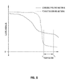
- FIG. 8 is a graph of a change in elastic modulus over increasing temperature for a polyvinyl chloride layer of the belting and a thermoplastic copolyester elastomer of the connector between the ends of the belt, illustrating a temperature range for effective joining;
- FIG. 9 is an upper top perspective view of the opposing ends of a conveyor belt having a different finger splice formation cut across the conveyor belt;
- FIG. 10 is an upper perspective view of the opposing ends of the conveyor belt shown in FIG. 9 , illustrating a pre-formed thermoplastic connector exploded away from a space between the ends;
- FIG. 11 is an upper perspective view of opposing ends of a conveyor belt, having a granular thermoplastic material inserted into the space between the cut ends of the conveyor belt;
- FIG. 11A is a cross-sectional view of the conveyor belt and the granular thermoplastic material shown in FIG. 11 , being moved into the space between the ends of the conveyor belt;
- FIG. 12 is a top perspective view of the opposing ends of the conveyor belt shown in
- FIG. 11 having the thermoplastic material engaged between the ends of the conveyor belt to form a seamless end connection
- FIG. 12A is a bottom perspective view of the opposing ends of the conveyor belt and the seamless end connection shown in FIG. 12 ;
- FIG. 12B is a cross-sectional view of the opposing ends of the conveyor belt and the seamless end connection shown in FIG. 12 ;
- FIG. 13A is a cross-sectional view of a conveyor belt having a rubber cover disposed over two layers of fabric that are spliced in a stepped splice formation;
- FIG. 13B a cross-sectional view of the conveyor belt shown in FIG. 13A , having a film sheet of thermoplastic material at the bottom layer of fabric in the stepped splice formation;
- FIG. 13C a cross-sectional view of the conveyor belt shown in FIG. 13B , having the film sheet of thermoplastic material thermally engaged between the exposed surfaces of the opposing ends of the conveyor belt at the stepped splice formation.
- an end connection 10 for a conveyor belt 12 can be formed in accordance with the present invention to form an endless loop or otherwise attach the conveyor belt to another section of belting.
- the end connection 10 for the conveyor belt 12 generally includes a thermoplastic connector 14 or joining material, such as a thermoplastic copolyester elastomer or like material that thermally engages between the opposing end portions 16 of the conveyor belt 12 .
- the end portions 16 of the belting may include a splice formation or configuration, such as a finger splice formation 18 , 118 , 218 ( FIGS. 1-12B ) or a step formation 318 ( FIGS. 13A-C ) or the like.
- the finger splice formation 18 is cut or formed to provide cut edges 20 that may be generally perpendicular to an upper surface of the conveyor belt 12 and expose the fabric carcass 22 of the conveyor belt 12 .
- the thermoplastic material adheres to the cut edges 20 and may impregnate the exposed woven filaments 24 of the fabric carcass 22 to form a generally seamless end connection that meets tension load requirements, while not using metal fasteners or the like.
- the conveyor belt 12 shown in FIGS. 1-12B includes a single-ply construction that has a single layer or sheet of fabric.
- a single-ply construction is not capable of being spliced in staggered, overlapping layers, as may be done at end connections for fabric conveyor belting having multiple distinct layers of fabric that can be separated by a layer of material, such as a flexible polymer or the like.
- the fabric carcass 22 of the conveyor belt 12 comprises a single fabric, such as a single layer or sheet of fabric, which may be an interwoven or solid woven fabric or a fabric with a plain weave or other type of generally known fabric construction. It is, however, contemplated that the end connection of the present invention may be formed with a conveyor belt that has multiple fabric layers, such as shown in FIGS. 13A-13C .
- the weave of the fabric carcass 22 generally defines a first set of filaments 24 a extending in one direction that are woven with a second set of filaments 24 b extending in another direction generally perpendicular to the first set of filaments.
- the conveyor belt 12 may convey loads in either direction of the first or second set of filaments (warp or weft directions) to have increased tensional load strength.
- the illustrated example of the conveyor belt 12 is configured to convey loads in a longitudinal direction, such that the first set of filaments 24 a are generally parallel to the direction of conveyance and the second set of filaments 24 b extend generally across the width of the conveyor belt 12 ( FIGS. 4A and 5A ).
- the fabric carcass 22 may be formed with polyester, polyamide, rayon, cotton, nylon, or any combination thereof. Also, the fabric carcass 22 can be any conventional weave, but preferably a weave with relatively wide openings or pores help to allow resin to impregnate and attach to the fabric carcass. It is also contemplated that the belt carcass 22 may be a composite with strands of monofilaments, such as carbon fibers, metals, or any of the fabric materials listed above, extending in the longitudinal direction and interconnected with other conceivable materials
- the conveyor belt 12 may also include a layer of polymer 26 disposed over a portion of the fabric carcass, such as over an upper surface or portion of the fabric carcass 22 , as illustrated in FIG. 4A .
- the layer of polymer 26 may be embedded into the pores of the fabric carcass and/or accumulated in a distinct layer on a top side of the fabric carcass 22 .
- the layer of polymer 26 may include a base layer 28 of thermoplastic resin that is at least partially impregnated in the openings or pores of the belt carcass 22 and accumulate on an exterior side of the belt carcass 22 to cure with a define thickness away from the belt carcass 22 .
- the base layer 28 may act as a reinforcement for the fabric carcass 22 and may include various materials, such as a polyvinyl chloride (PVC) resin with a plasticizer additive to provide robustness to the belt at a relatively low cost compared to a polyester elastomer or the like.
- the base layer may also define the upper exterior surface of the conveyor belt or a portion thereof, such as when a cover layer is not present.
- the layer of polymer 26 may also include an outer layer of polymer or a cover 30 that is disposed over the carcass, such as onto the cured base layer 28 , to form an exterior surface of the conveyor belt 12 .
- the cover 30 may be a polyester elastomer resin that is configured for conveyor systems, such as for resiliently interfacing with a die press of a cutting or stamping station.
- the cover layer 30 may include a thermoplastic copolyester elastomer, such as DuPont's Hytrel®, to provide improved resiliency and enhanced durability.
- the cover or cover layer 30 of elastomer may provide greater compressive resiliency than the reinforcing polymer layer 28 .
- the cover layer 30 may be disposed directly against and attached to the fabric carcass 22 , omitting the base layer 28 .
- the layer 26 or a portion thereof may be a thermosetting polymer, such as polyurethane, although some benefits of the heat application in forming the connector of the present invention would be reduced with the inclusion of such a thermosetting material.
- the splice formation 18 is cut or otherwise formed entirely through the belt 12 between the exterior surfaces of the belt to define a shape that aligns or meshes with the other opposing end portion 16 in a manner that provides a spacing between the cut edges 20 .
- the splice formation may include various shapes and patterns, such as a finger splice formation that includes longitudinal protrusions 32 or fingers spaced along an edge of the belt ends with spacing or openings defined between the longitudinal protrusions 32 . These longitudinal protrusions 32 may then be aligned with the spacing or openings between the longitudinal protrusions on the opposing end to define a longitudinal space between the opposing ends, such as a generally consistent gap that is greater than about 0.5 mm.
- the splice formation 18 is cut across the width of the conveyor belt 12 in a zig-zag pattern or shape that defines spaced wedge-shaped longitudinal protrusions 32 that matably align with the corresponding wedge-shaped openings 34 or spaces between the longitudinal protrusions.
- the splice formation 18 may be cut generally perpendicular across the width of the belt 12 , such as shown at FIGS. 1 and 2 , or at an angle across the width, such as shown with formation 118 at FIG. 3 .
- a single cut may be made through the conveyor belt, such as with a zig-zag shaped die or blade, and then the cut edges 20 may be moved apart and aligned to define the desired spacing 36 between the cut ends of the belt.
- FIGS. 9 and 10 Another example of a finger splice formation 218 is shown in FIGS. 9 and 10 with a shape that forms longitudinal protrusions having enlarged head portions and narrowed neck portions that engage similarly shaped openings.
- Mating this type of splice formation can improve the tension strength at the end connection, due to the engaged cut edges of the belt providing structural resistance in addition to the joining material of the end connection.
- two different cuts must be made for a spacing to be formed between the cut ends, such as with two differently shaped dies or blades.
- Another type of splice formation is a step or stepped splice formation 318 , which includes longitudinally separated cut edges at separated layers of the conveyor belt extending across the width of the conveyor belt.
- the cut edges 20 at the end portions 16 may be generally perpendicular to and extend between the upper and lower surfaces of the conveyor belt 12 .
- the cut edges 20 may have exposed woven filaments 24 of the fabric carcass 22 , such that an interior area of the woven filaments 24 are exposed along the cut edges 20 .
- the interior area of the woven filaments may not include the polymers of the layer of polymer 26 , which may, however, be impregnated in the pores between the woven filaments 24 .
- thermoplastic connector may then be inserted in the defined spacing 36 between the cut edges 20 of the splice formation 18 , such that the connector substantially fills or occupies the entire spacing 36 between the upper and lower exterior surfaces of the conveyor belt 12 .
- the connector 14 comprises a joining material, such as a thermoplastic copolyester elastomer, that is used to thermally engage between the cut edges of the opposing end portions.
- the thermoplastic copolyester elastomer may, for example, be DuPont's Hytrel® or a similar material.
- the joining material may be provided as a pre-formed piece that is shaped to be substantially identical to the defined space by the shape of the splicing configuration.
- Such a preformed piece may be injection molded, extruded, or cut from a sheet of material, such as with the same die or blade used to cut the finger splice formation in the belt.
- the joining material may include a granular substance that is moved into the space and leveled to have a thickness generally equal to the thickness of the conveyor belt. It is also contemplated that a combination of a pre-formed piece and a granular substance may be used, and further conceivable that the joining material may include an additive to form a paste or gel or the like.
- the thermal adhesion is provided by heating the opposing ends of the conveyor belt to cause the joining material to adhere to exposed filaments the fabric carcass at the cut edges of each opposing end portion.
- a heating device 38 may be provided to heat the opposing ends of the conveyor belt to a temperature greater than a melting point of the joining material.
- the illustrated heating device includes two opposing hot plates 38 a, 38 b that are pressed into contact with the opposing ends of the belt, with a foil 38 c, 38 d or other separation substrate placed between the belt and the contact surfaces of the hot plates to prevent adhesion to the hot plate itself. It is understood that various heating devices and assemblies by be used to heat the connector and form the seamless end connection of the present invention.
- the thermoplastic connector 14 softens or melts to adhere to the cut ends, such as by flowing into and filling or impregnating the open pores or interior area 25 of the exposed woven filaments 24 of the fabric carcass on each opposing cut edge. Also, when a portion of the layer of polymer 26 of the conveyor belt includes the same or similar material as the thermoplastic connector 14 , such as thermoplastic copolyester elastomer, the thermoplastic connector may fuse with the layer of polymer to provide an integral loop of the thermoplastic material. For example, as shown in FIG.
- the connector and the cover layer 30 of the conveyor belt 12 are made of thermoplastic copolyester elastomer, and after heating, have fused and integrated into a single and unitary piece of thermoplastic copolyester elastomer.
- an edge portion of the base layer 28 of polymer may be made of a different material, such as PVC, which may melt and flow into the thermoplastic connector, forming flow members 40 that extend into and integrate with the body of the joining material of the connector 14 .
- the seamless connection may be formed solely by the adhesive properties of the thermoplastic copolyester elastomer thermally engaging the surface area of the cut edges formed by the finger splice formation.
- an exemplary graph is provided in FIG. 8 that shows the elastic modulus behavior over a range of temperatures for a polymer material on the conveyor belt, such as PVC, and the polymer joining material of the connector, such as thermoplastic copolyester elastomer.
- the glass transition for the PVC spans a much greater temperature range than the connector, evidencing the high operating heat capability of the connector.
- the PVC begins to soften at around 80 degrees Celsius and does not reach its melting point until around 160 degrees Celsius, while the thermoplastic copolyester elastomer of the connector softens at around 110 degrees Celsius and reaches its melting point at around 140 degrees Celsius.
- the connector and the PVC have both generally reached their melting points at the first temperature T 1 , which defines the start of the optimal range of adhesion for the connector.
- the PVC begins to degrade at the second temperature T 2 , whereby the material can be damaged visually and/or structurally. Accordingly, the optimal range of adhesion extends from about from T 1 to T 2 .
- T 1 may be about 160 degrees Celsius and T 2 may be about 220 degrees Celsius, such that the preferable adhesion temperature for the heat source may be around 180 to 185 degrees Celsius.
- the dwell time for one exemplary connector and conveyor belt at the heating device to form the seamless end connection is between 1 and 10 minutes, although longer or shorter dwell times may be more preferable for differently dimensioned belts and alternatively configured heating devices.
- thermoplastic connector between the opposing ends of the conveyor belt forms a seamless end connection that may withstand at least four times a working load of the conveyor belt.
- the resulting end connection may be configured to withstand at least 200 lbs per inch of a width of the conveyor belt in an operational load condition.
- a thin layer of PVC material without any fiber or fabric backing may be disposed over the thermoplastic connector.
- the thin layer may then span the gap or space between the cut edges that is filed with the thermoplastic connector.
- This thin layer may be applied prior to heating the connector or after, as a separate heating step, to melt the thin layer over the connector.
- such a thin layer may have a thickness around 0.5 mm or less, and optionally, may be predisposed on or attached to an upper surface of a preformed connector.
- a conveyor belt 312 that includes a multiple fabric layer construction that is spliced in a step or stepped splice formation 318 at the opposing end portions 316 of the conveyor belt 312 .
- the conveyor belt 312 includes a cover layer 330 that is disposed over the base layer, such as a fabric carcass 322 having two or more fabric layers, and it may comprise a thermosetting polymer or rubber or the like, which can make a finger splice formation less desirable for forming the end connection.
- the stepped splice formation 318 is cut or otherwise formed entirely through the belt 312 between the exterior surfaces of the belt to define a shape that aligns or meshes with the other opposing end portion 316 in a manner that provides a stepped interface between the cut edges 320 .
- the illustrated stepped splice formation 318 includes longitudinally separated cut edges at separated layers of the conveyor belt extending across the width of the conveyor belt. As shown in FIG. 13A , at each end portion 316 of the belt, a lower layer 322 a of the fabric carcass 322 is separated from an upper layer 322 b that is attached to the cover layer 330 .
- the upper layer 322 b and the attached cover 330 are cut away from the lower layer to leave the remaining portion of the lower layer 322 a exposed along the width of the belt.
- the lower layer 332 a is cut away from the upper layer 322 b and the cover 330 , leaving the remaining upper layer and cover extending longitudinally from the cut edge of the lower layer a length that is substantially equal to the remaining lower layer at the other cut end.
- thermoplastic connector 314 comprising a thin layer or film sheet of thermoplastic copolyester elastomer is disposed over the upper surface of the extending portion of the lower layer 322 a .
- This piece or pieces of thermoplastic elastomer is then heated, such as with a heating device shown in FIGS. 6 and 6A , to soften and/or melt the connector material and press the material into the vertical spacing between the exposed edges of the cover and the upper and lower layers 322 b, 322 c of the fabric carcass.
- the layers of fabric may be infused or covered with a polymer, such as a thermoplastic or thermosetting polymeric material, which is thermally engaged by the connector between the exposed surfaces of the stepped splice formation. It is also contemplated that the cut ends of the fabric carcass 322 may be thermally engaged by the thermoplastic connector 314 , such as described in the embodiments discussed above. When the splice formations are aligned, the thermoplastic connector is thermally engaged and continuously interconnected between the ends for conveyor belt to form a seamless end connection.
- a polymer such as a thermoplastic or thermosetting polymeric material
Landscapes
- Engineering & Computer Science (AREA)
- Mechanical Engineering (AREA)
- General Engineering & Computer Science (AREA)
- Physics & Mathematics (AREA)
- Thermal Sciences (AREA)
- Textile Engineering (AREA)
- Geometry (AREA)
- Health & Medical Sciences (AREA)
- Toxicology (AREA)
- Belt Conveyors (AREA)
- Tires In General (AREA)
Abstract
Description
Claims (24)
Priority Applications (1)
| Application Number | Priority Date | Filing Date | Title |
|---|---|---|---|
| US15/405,784 US9829068B2 (en) | 2016-01-14 | 2017-01-13 | Seamless end connection for conveyor belts |
Applications Claiming Priority (2)
| Application Number | Priority Date | Filing Date | Title |
|---|---|---|---|
| US201662278511P | 2016-01-14 | 2016-01-14 | |
| US15/405,784 US9829068B2 (en) | 2016-01-14 | 2017-01-13 | Seamless end connection for conveyor belts |
Publications (2)
| Publication Number | Publication Date |
|---|---|
| US20170204937A1 US20170204937A1 (en) | 2017-07-20 |
| US9829068B2 true US9829068B2 (en) | 2017-11-28 |
Family
ID=59314454
Family Applications (1)
| Application Number | Title | Priority Date | Filing Date |
|---|---|---|---|
| US15/405,784 Active US9829068B2 (en) | 2016-01-14 | 2017-01-13 | Seamless end connection for conveyor belts |
Country Status (1)
| Country | Link |
|---|---|
| US (1) | US9829068B2 (en) |
Cited By (24)
| Publication number | Priority date | Publication date | Assignee | Title |
|---|---|---|---|---|
| US10188890B2 (en) | 2013-12-26 | 2019-01-29 | Icon Health & Fitness, Inc. | Magnetic resistance mechanism in a cable machine |
| US10252109B2 (en) | 2016-05-13 | 2019-04-09 | Icon Health & Fitness, Inc. | Weight platform treadmill |
| US10258828B2 (en) | 2015-01-16 | 2019-04-16 | Icon Health & Fitness, Inc. | Controls for an exercise device |
| US10272317B2 (en) | 2016-03-18 | 2019-04-30 | Icon Health & Fitness, Inc. | Lighted pace feature in a treadmill |
| US10279212B2 (en) | 2013-03-14 | 2019-05-07 | Icon Health & Fitness, Inc. | Strength training apparatus with flywheel and related methods |
| US10293211B2 (en) | 2016-03-18 | 2019-05-21 | Icon Health & Fitness, Inc. | Coordinated weight selection |
| US10343017B2 (en) | 2016-11-01 | 2019-07-09 | Icon Health & Fitness, Inc. | Distance sensor for console positioning |
| US10376736B2 (en) | 2016-10-12 | 2019-08-13 | Icon Health & Fitness, Inc. | Cooling an exercise device during a dive motor runway condition |
| US10426989B2 (en) | 2014-06-09 | 2019-10-01 | Icon Health & Fitness, Inc. | Cable system incorporated into a treadmill |
| US10433612B2 (en) | 2014-03-10 | 2019-10-08 | Icon Health & Fitness, Inc. | Pressure sensor to quantify work |
| US10441844B2 (en) | 2016-07-01 | 2019-10-15 | Icon Health & Fitness, Inc. | Cooling systems and methods for exercise equipment |
| US10471299B2 (en) | 2016-07-01 | 2019-11-12 | Icon Health & Fitness, Inc. | Systems and methods for cooling internal exercise equipment components |
| US10493349B2 (en) | 2016-03-18 | 2019-12-03 | Icon Health & Fitness, Inc. | Display on exercise device |
| US10500473B2 (en) | 2016-10-10 | 2019-12-10 | Icon Health & Fitness, Inc. | Console positioning |
| US10543395B2 (en) | 2016-12-05 | 2020-01-28 | Icon Health & Fitness, Inc. | Offsetting treadmill deck weight during operation |
| US10561894B2 (en) | 2016-03-18 | 2020-02-18 | Icon Health & Fitness, Inc. | Treadmill with removable supports |
| US10625137B2 (en) | 2016-03-18 | 2020-04-21 | Icon Health & Fitness, Inc. | Coordinated displays in an exercise device |
| US10661114B2 (en) | 2016-11-01 | 2020-05-26 | Icon Health & Fitness, Inc. | Body weight lift mechanism on treadmill |
| US10729965B2 (en) | 2017-12-22 | 2020-08-04 | Icon Health & Fitness, Inc. | Audible belt guide in a treadmill |
| US10953305B2 (en) | 2015-08-26 | 2021-03-23 | Icon Health & Fitness, Inc. | Strength exercise mechanisms |
| US11451108B2 (en) | 2017-08-16 | 2022-09-20 | Ifit Inc. | Systems and methods for axial impact resistance in electric motors |
| US20230122335A1 (en) * | 2020-03-20 | 2023-04-20 | Gates Corporation | Reinforced food grade belts and manufacturing method |
| US11654639B2 (en) * | 2019-07-11 | 2023-05-23 | Dutch Thermoplastic Components B.V. | Thermoplastic composite product |
| EP4261020A1 (en) * | 2022-04-15 | 2023-10-18 | Mitsubishi Heavy Industries, Ltd. | Composite material fusion method |
Families Citing this family (7)
| Publication number | Priority date | Publication date | Assignee | Title |
|---|---|---|---|---|
| DE102017217484A1 (en) * | 2017-09-29 | 2019-04-04 | Contitech Antriebssysteme Gmbh | Driving belt and method for its production |
| JP6510130B1 (en) * | 2017-11-21 | 2019-05-08 | ニッタ株式会社 | Belt belt, endless belt, and method for manufacturing the same |
| CH715075A1 (en) | 2018-06-06 | 2019-12-13 | Kunststoffwerk Ag Buchs | Plastic composite component. |
| KR102802424B1 (en) * | 2019-08-26 | 2025-05-07 | 삼성디스플레이 주식회사 | Apparatus for changing belt and method for changing belt using the same |
| FR3156494A1 (en) * | 2023-12-06 | 2025-06-13 | Compagnie Generale Des Etablissements Michelin | Transmission belt comprising a non-thermoplastic elastomeric matrix and thermoplastic bonding layers and method of manufacturing said belt |
| FR3156495A1 (en) * | 2023-12-06 | 2025-06-13 | Compagnie Generale Des Etablissements Michelin | Transmission belt comprising two superimposed layers of reinforcements embedded in a matrix and method of assembling said belt |
| EP4656902A1 (en) * | 2024-05-29 | 2025-12-03 | ContiTech Deutschland GmbH | Endless belt |
Citations (14)
| Publication number | Priority date | Publication date | Assignee | Title |
|---|---|---|---|---|
| US3300826A (en) * | 1964-05-08 | 1967-01-31 | Russell Mfg Co | Conveyor belt and method of jointing same |
| US4034617A (en) * | 1976-01-23 | 1977-07-12 | American Biltrite Inc. | Stepped belting splice |
| US4109543A (en) * | 1976-05-10 | 1978-08-29 | The Goodyear Tire & Rubber Company | Flexible composite laminate of woven fabric and thermoplastic material and method of making said laminate |
| US4427107A (en) * | 1979-05-19 | 1984-01-24 | J. H. Fenner & Co. Ltd. | Belting |
| US4767389A (en) * | 1986-04-08 | 1988-08-30 | Habasit Ag | Driving belt |
| US5316132A (en) | 1991-06-29 | 1994-05-31 | Fa. Ernst Siegling | Conveyor belt and method for its manufacture |
| US5951441A (en) * | 1997-12-19 | 1999-09-14 | Icon Health & Fitness, Inc. | Cushioned treadmill belts and methods of manufacture |
| US6488798B1 (en) * | 2000-11-28 | 2002-12-03 | Xerox Corporation | Method of making imageable seamed intermediate transfer belts having burnished seams |
| US20030201057A1 (en) * | 2000-03-15 | 2003-10-30 | Dolan Troy D. | Method for splicing a belt |
| US20060163042A1 (en) * | 2002-09-17 | 2006-07-27 | Jurg Vogt | Butt-weldable conveyor belt |
| US7650987B2 (en) * | 2004-08-26 | 2010-01-26 | Nitta Corporation | Belt connecting method, presetter, and belt connecting apparatus |
| US20120168285A1 (en) * | 2011-01-05 | 2012-07-05 | Honeywell International Inc. | Lightweight reinforced conveyor belt structure |
| US20140021021A1 (en) * | 2013-02-27 | 2014-01-23 | Veyance Technologies, Inc. | Conveyor belt |
| US20150144254A1 (en) * | 2013-11-20 | 2015-05-28 | Manroland Web Systems Gmbh | Method for producing an endless transport belt |
-
2017
- 2017-01-13 US US15/405,784 patent/US9829068B2/en active Active
Patent Citations (14)
| Publication number | Priority date | Publication date | Assignee | Title |
|---|---|---|---|---|
| US3300826A (en) * | 1964-05-08 | 1967-01-31 | Russell Mfg Co | Conveyor belt and method of jointing same |
| US4034617A (en) * | 1976-01-23 | 1977-07-12 | American Biltrite Inc. | Stepped belting splice |
| US4109543A (en) * | 1976-05-10 | 1978-08-29 | The Goodyear Tire & Rubber Company | Flexible composite laminate of woven fabric and thermoplastic material and method of making said laminate |
| US4427107A (en) * | 1979-05-19 | 1984-01-24 | J. H. Fenner & Co. Ltd. | Belting |
| US4767389A (en) * | 1986-04-08 | 1988-08-30 | Habasit Ag | Driving belt |
| US5316132A (en) | 1991-06-29 | 1994-05-31 | Fa. Ernst Siegling | Conveyor belt and method for its manufacture |
| US5951441A (en) * | 1997-12-19 | 1999-09-14 | Icon Health & Fitness, Inc. | Cushioned treadmill belts and methods of manufacture |
| US20030201057A1 (en) * | 2000-03-15 | 2003-10-30 | Dolan Troy D. | Method for splicing a belt |
| US6488798B1 (en) * | 2000-11-28 | 2002-12-03 | Xerox Corporation | Method of making imageable seamed intermediate transfer belts having burnished seams |
| US20060163042A1 (en) * | 2002-09-17 | 2006-07-27 | Jurg Vogt | Butt-weldable conveyor belt |
| US7650987B2 (en) * | 2004-08-26 | 2010-01-26 | Nitta Corporation | Belt connecting method, presetter, and belt connecting apparatus |
| US20120168285A1 (en) * | 2011-01-05 | 2012-07-05 | Honeywell International Inc. | Lightweight reinforced conveyor belt structure |
| US20140021021A1 (en) * | 2013-02-27 | 2014-01-23 | Veyance Technologies, Inc. | Conveyor belt |
| US20150144254A1 (en) * | 2013-11-20 | 2015-05-28 | Manroland Web Systems Gmbh | Method for producing an endless transport belt |
Non-Patent Citations (8)
| Title |
|---|
| Continental Contitech, "Installing and Splicing Textile Conveyor Belts", 2010 Conveyor Belt Group, pp. 1-28. |
| DuPont, "DuPont Product Information on DuPont Htyrel 4056P Thermoplastic Polyester Elastomer", Aug. 12, 2014. |
| Flexco, "Belt Splicing Solutions for Food Processing Operations", 2013. |
| Flexco, "Get The Facts About Conveyor Belt Splicing Techniques", 2010 Flexible Steel Lacing Company. |
| Flexco, "Novitool Pun M Mobile Finger Punch", 2014 Flexible Steel Lacing Company. |
| Flexco, "Technical Solutions for Belt conveyor Productivity", Insights, 2014 Flexible Steel Lacing Company. |
| Wikipedia, "Polyvinyl Chloride", Jul. 7, 2016, found at https://en.wikipedia.org/wiki/Polyvinyl-chloride. |
| Wikipedia, "Polyvinyl Chloride", Jul. 7, 2016, found at https://en.wikipedia.org/wiki/Polyvinyl—chloride. |
Cited By (26)
| Publication number | Priority date | Publication date | Assignee | Title |
|---|---|---|---|---|
| US10279212B2 (en) | 2013-03-14 | 2019-05-07 | Icon Health & Fitness, Inc. | Strength training apparatus with flywheel and related methods |
| US10188890B2 (en) | 2013-12-26 | 2019-01-29 | Icon Health & Fitness, Inc. | Magnetic resistance mechanism in a cable machine |
| US10433612B2 (en) | 2014-03-10 | 2019-10-08 | Icon Health & Fitness, Inc. | Pressure sensor to quantify work |
| US10426989B2 (en) | 2014-06-09 | 2019-10-01 | Icon Health & Fitness, Inc. | Cable system incorporated into a treadmill |
| US10258828B2 (en) | 2015-01-16 | 2019-04-16 | Icon Health & Fitness, Inc. | Controls for an exercise device |
| US10953305B2 (en) | 2015-08-26 | 2021-03-23 | Icon Health & Fitness, Inc. | Strength exercise mechanisms |
| US10272317B2 (en) | 2016-03-18 | 2019-04-30 | Icon Health & Fitness, Inc. | Lighted pace feature in a treadmill |
| US10293211B2 (en) | 2016-03-18 | 2019-05-21 | Icon Health & Fitness, Inc. | Coordinated weight selection |
| US10625137B2 (en) | 2016-03-18 | 2020-04-21 | Icon Health & Fitness, Inc. | Coordinated displays in an exercise device |
| US10493349B2 (en) | 2016-03-18 | 2019-12-03 | Icon Health & Fitness, Inc. | Display on exercise device |
| US10561894B2 (en) | 2016-03-18 | 2020-02-18 | Icon Health & Fitness, Inc. | Treadmill with removable supports |
| US10252109B2 (en) | 2016-05-13 | 2019-04-09 | Icon Health & Fitness, Inc. | Weight platform treadmill |
| US10441844B2 (en) | 2016-07-01 | 2019-10-15 | Icon Health & Fitness, Inc. | Cooling systems and methods for exercise equipment |
| US10471299B2 (en) | 2016-07-01 | 2019-11-12 | Icon Health & Fitness, Inc. | Systems and methods for cooling internal exercise equipment components |
| US10500473B2 (en) | 2016-10-10 | 2019-12-10 | Icon Health & Fitness, Inc. | Console positioning |
| US10376736B2 (en) | 2016-10-12 | 2019-08-13 | Icon Health & Fitness, Inc. | Cooling an exercise device during a dive motor runway condition |
| US10343017B2 (en) | 2016-11-01 | 2019-07-09 | Icon Health & Fitness, Inc. | Distance sensor for console positioning |
| US10661114B2 (en) | 2016-11-01 | 2020-05-26 | Icon Health & Fitness, Inc. | Body weight lift mechanism on treadmill |
| US10543395B2 (en) | 2016-12-05 | 2020-01-28 | Icon Health & Fitness, Inc. | Offsetting treadmill deck weight during operation |
| US11451108B2 (en) | 2017-08-16 | 2022-09-20 | Ifit Inc. | Systems and methods for axial impact resistance in electric motors |
| US10729965B2 (en) | 2017-12-22 | 2020-08-04 | Icon Health & Fitness, Inc. | Audible belt guide in a treadmill |
| US11654639B2 (en) * | 2019-07-11 | 2023-05-23 | Dutch Thermoplastic Components B.V. | Thermoplastic composite product |
| US20230122335A1 (en) * | 2020-03-20 | 2023-04-20 | Gates Corporation | Reinforced food grade belts and manufacturing method |
| US12234097B2 (en) * | 2020-03-20 | 2025-02-25 | Gates Corporation | Reinforced food grade belts and manufacturing method |
| EP4261020A1 (en) * | 2022-04-15 | 2023-10-18 | Mitsubishi Heavy Industries, Ltd. | Composite material fusion method |
| JP2023157640A (en) * | 2022-04-15 | 2023-10-26 | 三菱重工業株式会社 | Composite fusion method |
Also Published As
| Publication number | Publication date |
|---|---|
| US20170204937A1 (en) | 2017-07-20 |
Similar Documents
| Publication | Publication Date | Title |
|---|---|---|
| US9829068B2 (en) | Seamless end connection for conveyor belts | |
| CA1307684C (en) | Thermoplastic composite fasteners | |
| RU2684123C2 (en) | Method for joining at least two assemblies and corresponding joined structure | |
| KR100502762B1 (en) | Belt reinforcing material and belt constructed therewith | |
| US7244487B2 (en) | Apparatus, system, and method of joining structural components with a tapered tension bond joint | |
| US4184589A (en) | Dimensionally stable synthetic conveyor belt | |
| CN102405316A (en) | Seam for an industrial fabric and seaming element therefor | |
| US6913810B2 (en) | Interface tape | |
| CN104011429B (en) | Conveyor belt with multi-layer impregnated fabric cover | |
| CA2661964A1 (en) | Method for producing joined belt | |
| HK1038947A1 (en) | Surface fastener | |
| CN1330266C (en) | Sealed slide fasteners with teeth that engage the straps connected by them | |
| JP7425723B2 (en) | Method of manufacturing a composite part including a core and one or more skin regions | |
| CZ2004540A3 (en) | Method of forming a continuous belt for a belt-type separator device | |
| US7950213B2 (en) | Reinforced belt having reduced electrical resistivity and method for producing same | |
| CA2448854C (en) | Splicing joint and method for synchronous drive belt | |
| CN113874255B (en) | Resin molded body with surface fixing member, method for producing the same, and method for fixing automobile ceiling material to vehicle body | |
| US20030072912A1 (en) | Connected fastening members and process for production of resin molded article with fastening member | |
| US3558390A (en) | Process for manufacturing power transmission belts of synthetic material | |
| CZ202596A3 (en) | Detachable connecting device for conveyor belts | |
| JP7446105B2 (en) | Endless belt and endless belt manufacturing method | |
| US9457539B2 (en) | Compliant slit film seaming element | |
| CN106794613A (en) | The shock insulation insert of pipe clamp and the method for this insert of manufacture | |
| US7621114B1 (en) | Reinforced belt having reduced electrical resistivity and method for producing same | |
| EP1241378B1 (en) | Transfer belt |
Legal Events
| Date | Code | Title | Description |
|---|---|---|---|
| AS | Assignment |
Owner name: UNIBAND USA, LLC, MICHIGAN Free format text: ASSIGNMENT OF ASSIGNORS INTEREST;ASSIGNOR:MARCHETTI, FRANCO MILCO;REEL/FRAME:040970/0424 Effective date: 20170103 |
|
| STCF | Information on status: patent grant |
Free format text: PATENTED CASE |
|
| MAFP | Maintenance fee payment |
Free format text: PAYMENT OF MAINTENANCE FEE, 4TH YR, SMALL ENTITY (ORIGINAL EVENT CODE: M2551); ENTITY STATUS OF PATENT OWNER: SMALL ENTITY Year of fee payment: 4 |
|
| FEPP | Fee payment procedure |
Free format text: MAINTENANCE FEE REMINDER MAILED (ORIGINAL EVENT CODE: REM.); ENTITY STATUS OF PATENT OWNER: SMALL ENTITY |
|
| FEPP | Fee payment procedure |
Free format text: 7.5 YR SURCHARGE - LATE PMT W/IN 6 MO, SMALL ENTITY (ORIGINAL EVENT CODE: M2555); ENTITY STATUS OF PATENT OWNER: SMALL ENTITY |
|
| MAFP | Maintenance fee payment |
Free format text: PAYMENT OF MAINTENANCE FEE, 8TH YR, SMALL ENTITY (ORIGINAL EVENT CODE: M2552); ENTITY STATUS OF PATENT OWNER: SMALL ENTITY Year of fee payment: 8 |