US9828152B2 - In-line cable tie with flexible head - Google Patents
In-line cable tie with flexible head Download PDFInfo
- Publication number
- US9828152B2 US9828152B2 US14/793,822 US201514793822A US9828152B2 US 9828152 B2 US9828152 B2 US 9828152B2 US 201514793822 A US201514793822 A US 201514793822A US 9828152 B2 US9828152 B2 US 9828152B2
- Authority
- US
- United States
- Prior art keywords
- head
- strap
- passageway
- notches
- teeth
- Prior art date
- Legal status (The legal status is an assumption and is not a legal conclusion. Google has not performed a legal analysis and makes no representation as to the accuracy of the status listed.)
- Active, expires
Links
Images


Classifications
-
- B—PERFORMING OPERATIONS; TRANSPORTING
- B65—CONVEYING; PACKING; STORING; HANDLING THIN OR FILAMENTARY MATERIAL
- B65D—CONTAINERS FOR STORAGE OR TRANSPORT OF ARTICLES OR MATERIALS, e.g. BAGS, BARRELS, BOTTLES, BOXES, CANS, CARTONS, CRATES, DRUMS, JARS, TANKS, HOPPERS, FORWARDING CONTAINERS; ACCESSORIES, CLOSURES, OR FITTINGS THEREFOR; PACKAGING ELEMENTS; PACKAGES
- B65D63/00—Flexible elongated elements, e.g. straps, for bundling or supporting articles
- B65D63/10—Non-metallic straps, tapes, or bands; Filamentary elements, e.g. strings, threads or wires; Joints between ends thereof
- B65D63/1018—Joints produced by application of integral securing members, e.g. buckles, wedges, tongue and slot, locking head and teeth or the like
- B65D63/1027—Joints produced by application of integral securing members, e.g. buckles, wedges, tongue and slot, locking head and teeth or the like the integral securing member being formed as a female and male locking member, e.g. locking head and locking teeth, or the like
- B65D63/1063—Joints produced by application of integral securing members, e.g. buckles, wedges, tongue and slot, locking head and teeth or the like the integral securing member being formed as a female and male locking member, e.g. locking head and locking teeth, or the like the female locking member being provided with at least one plastic barb
- B65D63/1072—Joints produced by application of integral securing members, e.g. buckles, wedges, tongue and slot, locking head and teeth or the like the integral securing member being formed as a female and male locking member, e.g. locking head and locking teeth, or the like the female locking member being provided with at least one plastic barb the barb having a plurality of serrations
-
- B—PERFORMING OPERATIONS; TRANSPORTING
- B65—CONVEYING; PACKING; STORING; HANDLING THIN OR FILAMENTARY MATERIAL
- B65D—CONTAINERS FOR STORAGE OR TRANSPORT OF ARTICLES OR MATERIALS, e.g. BAGS, BARRELS, BOTTLES, BOXES, CANS, CARTONS, CRATES, DRUMS, JARS, TANKS, HOPPERS, FORWARDING CONTAINERS; ACCESSORIES, CLOSURES, OR FITTINGS THEREFOR; PACKAGING ELEMENTS; PACKAGES
- B65D2563/00—Flexible elongated elements, e.g. straps for bundling or supporting atricles
- B65D2563/10—Non-metallic straps, tapes or bands; Filamentary elements, e.g. strings, threads, wires; Joints between ends thereof
- B65D2563/101—Details of non-metallic straps, tapes or bands
Definitions
- the present invention relates to cable ties used to bundle an article or a group of articles. More specifically, the present invention relates to low profile cable ties having a flexible head.
- cable ties to bundle or secure a group of articles.
- Known cable ties of conventional construction are elongate members having a head at one end, a tail at the other end, and a longitudinal strap therebetween. The strap is wrapped around a bundle of articles and the tail is inserted through an aperture or passageway in the head.
- the head of the cable tie typically includes a locking element which is engageable with the body of the strap so that when the tail is pulled through the passageway in the head, the locking element secures the strap body in the head.
- low profile cable ties are preferred as they sit low to the bundle and resist snagging.
- the strap is inserted into the head in a direction substantially parallel to the strap body.
- a low profile tie includes an elongate strap having a tail at one end.
- a locking head positioned at the other end of the strap has a passageway therethrough for insertable receipt of the tail.
- the strap includes a planar strap surface between said tail and the locking head having a plurality of notches therealong.
- the locking head includes a base portion and a head portion flexibly connected to the base portion with the passageway formed therebetween.
- the head portion includes a plurality of locking teeth extending into the passageway for engagement with the notches of said strap body upon the insertion of said tail.
- the notches engage a number of teeth less than all of the locking teeth upon the insertion of the strap into said passageway.
- the head is flexibly pivotal so that more than the locking teeth engage the notches upon an attempt to withdraw said strap from said head.
- FIG. 1 is a perspective showing of the low profile cable tie of the present invention.
- FIG. 2 is a partial plan view of the cable tie of FIG. 1 .
- FIG. 3 is a partial perspective showing of the cable tie of FIG. 1 in the bundled position.
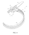
- FIG. 4 shows the cable tie of FIG. 1 in the tail insertion position.
- FIG. 5 shows the cable tie of FIG. 1 in the tail tensioned position.
- FIGS. 1-5 show a cable tie 10 of the present invention.
- Cable tie 10 is an elongate member including a locking head 12 , an opposed tail 14 , and an elongate strap body 16 therebetween.
- Strap body 16 is typically planar shaped having first and second opposed major surface 18 and 20 .
- Head 12 includes passageway 22 therethrough.
- Passageway 22 includes strap ingress end 24 and strap egress end 26 .
- Strap surface 18 includes a plurality of spaced apart teeth-like notches 24 along the length thereof.
- Locking head 12 includes a base portion 30 formed at one end of strap body 16 and a head portion 32 spaced from the base portion 30 .
- Passageway 22 is defined between base portion 30 and head portion 22 .
- Head portion 32 is connected to base portion 30 by flexible connection 34 which permits pivoting of head portion 32 with respect to base portion 30 .
- the flexible connection 34 is formed by a pair of spaced apart flexible rails 34 a and 34 b which also define passageway 22 therebetween.
- Base portion 30 and head portion 32 include mutually facing surfaces 30 a and 32 a .
- Surface 30 a of base portion is generally flat so as to support the flat surface 20 of strap body 16 .
- Surface 32 a includes a plurality of teeth 38 , more fully shown in FIGS. 4 and 5 , which extend into passageway 22 .
- three teeth 38 are shown extending into passageway 22 from surface 32 a . It may be appreciated that such number is only an example.
- the three teeth 38 a , 38 b , 38 c are arranged in succession in the direction of insertion (arrow A) of the strap body into passageway 22 .
- the last tooth 38 c extends further into the passageway than the other two teeth 38 a and 38 b , which are successively recessed.
- Tooth 38 c is positioned such that upon insertion of strap body 16 into passageway 22 , the single tooth 38 c (or less than all of the teeth) engages the notches 24 on the strap body 16 . Such engagement of the single tooth 38 c with the notches 24 allows the strap body 16 to be easily inserted through the passageway 22 in the direction of arrow A with low insertion force.
- the teeth are fixed and the head portion 32 is flexible or rotatable thereby providing greater retention force.
- the strap body 16 extends from the passageway 22 at an angle to the passageway of preferably about 40° to 50°. At such an angle and with the rotation of head portion 32 affected by the flexible connection, additional teeth 38 a and 38 b engage the notches. This engagement of multiple teeth with the notches provides a high retention force for the strap in the head. This angle also allows the low profile tie to be tensioned using conventional cable tie tools.
- the present invention provides a low profile cable tie which allows insertion of the tail into the head with a low insertion force, yet once bundled, provides a high retention force for the strap in the head.
Landscapes
- Engineering & Computer Science (AREA)
- Mechanical Engineering (AREA)
- Package Frames And Binding Bands (AREA)
- General Engineering & Computer Science (AREA)
- Clamps And Clips (AREA)
- Buckles (AREA)
Abstract
A low profile cable tie includes a strap having a tail at one end and a locking head at the other end. The locking head has passage for receipt of the tail therethrough. The strap includes a planar surface between the tail and the locking head having a plurality of notches therealong. The locking head includes a base portion and a head portion flexibly connected to the base portion with the passageway formed therebetween. The head portion includes a plurality of locking teeth extending into the passageway for engagement with the notches of the strap body. The notches engage a number of teeth less than all of the locking teeth upon insertion of the strap into the passageway. The head is flexibly pivotable so that more than the number of locking teeth engage the notches upon attempt to withdraw the strap from the head.
Description
This application claims priority to U.S. Provisional Patent Application No. 62/024,612 filed on Jul. 15, 2014, the contents of which is incorporated herein by reference in its entirety.
The present invention relates to cable ties used to bundle an article or a group of articles. More specifically, the present invention relates to low profile cable ties having a flexible head.
The use of cable ties to bundle or secure a group of articles is well known. Known cable ties of conventional construction are elongate members having a head at one end, a tail at the other end, and a longitudinal strap therebetween. The strap is wrapped around a bundle of articles and the tail is inserted through an aperture or passageway in the head. The head of the cable tie typically includes a locking element which is engageable with the body of the strap so that when the tail is pulled through the passageway in the head, the locking element secures the strap body in the head.
In certain situations, low profile cable ties are preferred as they sit low to the bundle and resist snagging. To maintain the low profile, the strap is inserted into the head in a direction substantially parallel to the strap body.
Conventional cable tie tools are used to pull the tail of the cable tie through the head of traditional cable ties. These tools typically cannot be effectively used on low profile cable ties.
Moreover, in such cable ties it is desirable to maintain a low insertion force for the tail into the head and a high retention force resisting withdrawal.
A low profile tie includes an elongate strap having a tail at one end. A locking head positioned at the other end of the strap has a passageway therethrough for insertable receipt of the tail. The strap includes a planar strap surface between said tail and the locking head having a plurality of notches therealong. The locking head includes a base portion and a head portion flexibly connected to the base portion with the passageway formed therebetween. The head portion includes a plurality of locking teeth extending into the passageway for engagement with the notches of said strap body upon the insertion of said tail. The notches engage a number of teeth less than all of the locking teeth upon the insertion of the strap into said passageway. The head is flexibly pivotal so that more than the locking teeth engage the notches upon an attempt to withdraw said strap from said head.
Locking head 12 includes a base portion 30 formed at one end of strap body 16 and a head portion 32 spaced from the base portion 30. Passageway 22 is defined between base portion 30 and head portion 22.
Referring additionally to FIGS. 3-5 , three teeth 38 are shown extending into passageway 22 from surface 32 a. It may be appreciated that such number is only an example.
The three teeth 38 a, 38 b, 38 c are arranged in succession in the direction of insertion (arrow A) of the strap body into passageway 22. The last tooth 38 c extends further into the passageway than the other two teeth 38 a and 38 b, which are successively recessed.
Once the strap is tightly bundled, an attempt to move the strap in a direction of arrow B (FIG. 5 ), opposite arrow A, such as by release of the tightening tension, the head portion 32 pivots inwardly towards base portion 30. The flexible rails 34 a and 34 b permit such rotation of head portion 32.
In the present invention, the teeth are fixed and the head portion 32 is flexible or rotatable thereby providing greater retention force.
The strap body 16 extends from the passageway 22 at an angle to the passageway of preferably about 40° to 50°. At such an angle and with the rotation of head portion 32 affected by the flexible connection, additional teeth 38 a and 38 b engage the notches. This engagement of multiple teeth with the notches provides a high retention force for the strap in the head. This angle also allows the low profile tie to be tensioned using conventional cable tie tools.
Thus, the present invention provides a low profile cable tie which allows insertion of the tail into the head with a low insertion force, yet once bundled, provides a high retention force for the strap in the head.
Various changes to the foregoing described and shown structures would now be evident to those skilled in the art. Accordingly, the particularly disclosed scope of the invention is set forth in the following claims.
Claims (10)
1. A low profile tie comprising:
an elongate strap having a tail at one end; and
a locking head at the other end of said strap, said locking head having a passageway, wherein the tail is adapted to be inserted through the passageway in the head in a direction substantially parallel to said strap;
said strap including a planar strap surface between said tail and said locking head having a plurality of notches therealong;
said locking head including a base portion and a head portion, wherein said head portion is connected to said base portion by a flexible connection located between said head portion and said base portion, said flexible connection including a pair of spaced apart rails, said passageway formed between the head portion and the base portion and between said spaced apart rails;
said head portion including a plurality of locking teeth extending into said passageway for engagement with said notches of said strap surface;
wherein said locking head is arranged such that a number of teeth less than all of said locking teeth engage said notches upon said insertion of said strap into said passageway and wherein said head portion is flexibly pivotal by said flexible connection so that more than said number of said locking teeth engage said notches upon an attempt to withdraw said strap from said head.
2. A low profile tie of claim 1 wherein said head portion is rotatable with respect to said base portion.
3. A low profile tie of claim 1 wherein said head portion includes three teeth and wherein said notches engage one of said teeth upon insertion of said strap into said passageway.
4. A low profile tie of claim 3 wherein said last tooth in the direction of said insertion extends into said passageway a further distance than the other two said teeth.
5. A low profile tie of claim 3 wherein upon said attempt to withdraw said strap from said head all three of said teeth engage said notches.
6. A low profile tie of claim 1 wherein the tail extends from the head, upon insertion, at an angle of between about 40°-50°.
7. A low profile tie comprising:
an elongate strap having a tail at one end; and
a locking head at the other end of said strap, said locking head having a passageway therethrough for insertable receipt of said tail;
said strap including a planar strap surface between said tail and said locking head and having a plurality of notches therealong;
said locking head including a base portion and a head portion flexibly connected to said base portion by a flexible connection between said head portion and said base portion said flexible connection including a pair of spaced apart rails with said passageway formed thereat;
said head portion including a plurality of locking teeth extending into said passageway for engagement with said notches of said strap surface;
one of said locking teeth engaging said notches upon said insertion of said strap body including said passageway and said head portion being rotatable with respect to said base portion to place all of said teeth into engagement with said notches upon an attempt to withdraw said strap from said passageway.
8. A low profile tie of claim 7 wherein said head portion includes three teeth and wherein said notches engage one of said teeth upon insertion of said strap into said passageway.
9. A low profile tie of claim 8 wherein upon attempting to withdraw said strap from said head, all three of said teeth engage said notches.
10. A low profile tie of claim 7 wherein the tail extends from said head, upon insertion, at an angle of about 40°-50°.
Priority Applications (1)
| Application Number | Priority Date | Filing Date | Title |
|---|---|---|---|
| US14/793,822 US9828152B2 (en) | 2014-07-15 | 2015-07-08 | In-line cable tie with flexible head |
Applications Claiming Priority (2)
| Application Number | Priority Date | Filing Date | Title |
|---|---|---|---|
| US201462024612P | 2014-07-15 | 2014-07-15 | |
| US14/793,822 US9828152B2 (en) | 2014-07-15 | 2015-07-08 | In-line cable tie with flexible head |
Publications (2)
| Publication Number | Publication Date |
|---|---|
| US20160016709A1 US20160016709A1 (en) | 2016-01-21 |
| US9828152B2 true US9828152B2 (en) | 2017-11-28 |
Family
ID=53969089
Family Applications (1)
| Application Number | Title | Priority Date | Filing Date |
|---|---|---|---|
| US14/793,822 Active 2035-07-26 US9828152B2 (en) | 2014-07-15 | 2015-07-08 | In-line cable tie with flexible head |
Country Status (10)
| Country | Link |
|---|---|
| US (1) | US9828152B2 (en) |
| EP (1) | EP2974977B1 (en) |
| JP (1) | JP6138867B2 (en) |
| CN (1) | CN105508739B (en) |
| AU (1) | AU2015204299B2 (en) |
| CA (1) | CA2897642C (en) |
| DK (1) | DK2974977T3 (en) |
| ES (1) | ES2635665T3 (en) |
| MX (1) | MX360310B (en) |
| PL (1) | PL2974977T3 (en) |
Cited By (2)
| Publication number | Priority date | Publication date | Assignee | Title |
|---|---|---|---|---|
| US10823318B2 (en) | 2016-06-10 | 2020-11-03 | Xenios Ag | Cable tie |
| US12365524B2 (en) | 2022-07-07 | 2025-07-22 | Abb Schweiz Ag | Cable bundling system |
Families Citing this family (3)
| Publication number | Priority date | Publication date | Assignee | Title |
|---|---|---|---|---|
| US9127486B2 (en) * | 2010-01-25 | 2015-09-08 | Vision Industries Group, Inc. | Sash window and door transportation clip assembly |
| CN110371478A (en) * | 2019-08-07 | 2019-10-25 | 沈阳飞机工业(集团)有限公司 | A kind of conducting wire beaming device and its application method |
| CN114751087B (en) * | 2022-04-25 | 2024-04-02 | 国网黑龙江省电力有限公司双鸭山供电公司 | Power cable strapping tape |
Citations (43)
| Publication number | Priority date | Publication date | Assignee | Title |
|---|---|---|---|---|
| US2977145A (en) | 1958-09-19 | 1961-03-28 | Rifkin & Co A | Seal construction having plural female elements |
| US3588962A (en) | 1970-03-12 | 1971-06-29 | Burndy Corp | Bundling strap |
| US3605199A (en) | 1970-01-08 | 1971-09-20 | All States Plastic Mfg Co | Bundle tie |
| US3660869A (en) | 1969-05-01 | 1972-05-09 | Panduit Corp | One-piece cable tie |
| US3735448A (en) | 1970-02-25 | 1973-05-29 | Buchanan Electrical Prod Corp | Wire tie |
| US3872547A (en) | 1970-08-25 | 1975-03-25 | Panduit Corp | One-piece cable tie |
| US3886630A (en) | 1974-07-15 | 1975-06-03 | Manx Mail Order Limited | Cable tie clips |
| US3887965A (en) * | 1973-09-04 | 1975-06-10 | Fastway Fasteners | Bundling tie |
| US3952373A (en) | 1974-09-27 | 1976-04-27 | Thomas & Betts Corporation | Cable bundling strap |
| US3965538A (en) | 1969-05-05 | 1976-06-29 | Panduit Corporation | Integral cable tie |
| US3967345A (en) | 1975-02-07 | 1976-07-06 | Tokyo Style Company, Ltd. | Binding strap |
| US3973292A (en) * | 1973-06-19 | 1976-08-10 | Bonnet R Y G | Collar |
| US4003106A (en) | 1975-06-19 | 1977-01-18 | Panduit Corporation | Ladder strap cable tie with pivotal dog |
| US4092765A (en) | 1976-02-12 | 1978-06-06 | Dennison Manufacturing Company | Miniaturized harnessing device |
| US4287644A (en) | 1979-01-30 | 1981-09-08 | Le Grand S.A. | Coil loop type cable tie |
| US4413380A (en) | 1980-01-08 | 1983-11-08 | Satogosei Co., Ltd. | Binding locker |
| US4490887A (en) * | 1981-09-23 | 1985-01-01 | Legrand | Cable tie |
| US4580319A (en) * | 1980-07-14 | 1986-04-08 | Dennison Manufacturing Company | Bundling of objects |
| US4658478A (en) * | 1980-07-14 | 1987-04-21 | Dennison Manufacturing Company | Bundling of objects |
| US4776067A (en) | 1986-02-17 | 1988-10-11 | Sorensen Jens Ole | Cable tie |
| US5295285A (en) | 1993-01-19 | 1994-03-22 | All-States Inc. | Cable tie |
| US5414904A (en) | 1992-12-11 | 1995-05-16 | Sampson; Gregory | Multi-use fastener system |
| JPH0940005A (en) | 1995-07-25 | 1997-02-10 | Kitagawa Ind Co Ltd | Tying band |
| US5675870A (en) | 1996-10-01 | 1997-10-14 | Avery Dennison Corporation | Cable tie |
| US5745957A (en) | 1997-03-26 | 1998-05-05 | Thomas & Betts Corporation | In-line cable tie |
| US5781975A (en) | 1997-03-12 | 1998-07-21 | Thomas & Betts Corporation | Flexible platform for cable tie barb |
| US5836053A (en) | 1996-10-01 | 1998-11-17 | Avery Dennison Corporation | Cable tie |
| JPH10318217A (en) | 1997-05-21 | 1998-12-02 | Nippon Shoji Kk | Band for fixing |
| US5890265A (en) | 1995-12-13 | 1999-04-06 | Tyton Hellermann Corporation | Parallel entry tie |
| US6185792B1 (en) | 1997-11-21 | 2001-02-13 | Thomas & Betts International, Inc. | Bi-directional self-locking cable tie |
| US20020083559A1 (en) | 2001-01-03 | 2002-07-04 | Hatch David A. | Latchable tie |
| US6449808B1 (en) * | 2000-08-10 | 2002-09-17 | E. J. Brooks Company | Security seal with flag grip |
| US6511108B1 (en) * | 1999-10-07 | 2003-01-28 | E. J. Brooks Company | Locking seal with distortable body |
| US20040049890A1 (en) * | 2001-02-12 | 2004-03-18 | Viktor Kurmis | Array and method for tying cable trees and the like and method for the production of strips |
| US6751828B2 (en) | 2000-03-09 | 2004-06-22 | Hellermann Tyton Gmbh | Device for bundling objects, such as cable bundles |
| US6807714B2 (en) | 2002-03-04 | 2004-10-26 | Panduit Corp. | Cable tie having stepped down strap body teeth |
| US7017237B2 (en) | 2003-12-02 | 2006-03-28 | Thomas & Betts International, Inc. | High performance cable tie |
| US20070175001A1 (en) | 2006-01-27 | 2007-08-02 | Tomory Dennis G | Tie device with cam action lock pawl |
| EP1818275A1 (en) | 2006-02-09 | 2007-08-15 | Panduit Corporation | Cable tie with fixed and hinged locking mechanisms |
| WO2009089316A1 (en) | 2008-01-09 | 2009-07-16 | Panduit Corp. | Elastomeric releasable cable tie |
| US20120272485A1 (en) | 2011-04-26 | 2012-11-01 | Liang Davey Z | Cable Tie |
| JP2013113330A (en) | 2011-11-25 | 2013-06-10 | Funai Electric Co Ltd | Binding band |
| US9015906B2 (en) * | 2011-08-03 | 2015-04-28 | Thomas & Betts International, Inc. | Cable tie with improved pawl |
Family Cites Families (5)
| Publication number | Priority date | Publication date | Assignee | Title |
|---|---|---|---|---|
| US6560822B2 (en) * | 2001-05-15 | 2003-05-13 | Panduit Corp. | Low profile cable tie with prebent strap |
| CN201639211U (en) * | 2010-03-22 | 2010-11-17 | 浙江吉利汽车研究院有限公司 | A detachable cable tie |
| JP2012253909A (en) * | 2011-06-03 | 2012-12-20 | Daiwa Kasei Kogyo Kk | Belt clamp |
| CN203374988U (en) * | 2013-07-16 | 2014-01-01 | 上海海泰汽配有限公司 | Pull buckle binding tie capable of being opened conveniently |
| CN203604821U (en) * | 2013-12-02 | 2014-05-21 | 天津市天龙得冷成型部件有限公司 | Clip bolt of locking clip |
-
2015
- 2015-07-08 US US14/793,822 patent/US9828152B2/en active Active
- 2015-07-14 DK DK15176671.4T patent/DK2974977T3/en active
- 2015-07-14 AU AU2015204299A patent/AU2015204299B2/en not_active Ceased
- 2015-07-14 PL PL15176671T patent/PL2974977T3/en unknown
- 2015-07-14 ES ES15176671.4T patent/ES2635665T3/en active Active
- 2015-07-14 JP JP2015140301A patent/JP6138867B2/en not_active Expired - Fee Related
- 2015-07-14 CN CN201510589105.XA patent/CN105508739B/en active Active
- 2015-07-14 EP EP15176671.4A patent/EP2974977B1/en active Active
- 2015-07-15 CA CA2897642A patent/CA2897642C/en active Active
- 2015-07-15 MX MX2015009144A patent/MX360310B/en active IP Right Grant
Patent Citations (50)
| Publication number | Priority date | Publication date | Assignee | Title |
|---|---|---|---|---|
| US2977145A (en) | 1958-09-19 | 1961-03-28 | Rifkin & Co A | Seal construction having plural female elements |
| US3660869A (en) | 1969-05-01 | 1972-05-09 | Panduit Corp | One-piece cable tie |
| GB1287651A (en) | 1969-05-01 | 1972-09-06 | Panduit Corp | One-piece bundling tie |
| US3965538A (en) | 1969-05-05 | 1976-06-29 | Panduit Corporation | Integral cable tie |
| US3605199A (en) | 1970-01-08 | 1971-09-20 | All States Plastic Mfg Co | Bundle tie |
| US3735448A (en) | 1970-02-25 | 1973-05-29 | Buchanan Electrical Prod Corp | Wire tie |
| US3588962A (en) | 1970-03-12 | 1971-06-29 | Burndy Corp | Bundling strap |
| US3872547A (en) | 1970-08-25 | 1975-03-25 | Panduit Corp | One-piece cable tie |
| US3973292A (en) * | 1973-06-19 | 1976-08-10 | Bonnet R Y G | Collar |
| US3887965A (en) * | 1973-09-04 | 1975-06-10 | Fastway Fasteners | Bundling tie |
| US3886630A (en) | 1974-07-15 | 1975-06-03 | Manx Mail Order Limited | Cable tie clips |
| US3952373A (en) | 1974-09-27 | 1976-04-27 | Thomas & Betts Corporation | Cable bundling strap |
| US3967345A (en) | 1975-02-07 | 1976-07-06 | Tokyo Style Company, Ltd. | Binding strap |
| US4003106A (en) | 1975-06-19 | 1977-01-18 | Panduit Corporation | Ladder strap cable tie with pivotal dog |
| US4092765A (en) | 1976-02-12 | 1978-06-06 | Dennison Manufacturing Company | Miniaturized harnessing device |
| US4287644A (en) | 1979-01-30 | 1981-09-08 | Le Grand S.A. | Coil loop type cable tie |
| US4413380A (en) | 1980-01-08 | 1983-11-08 | Satogosei Co., Ltd. | Binding locker |
| US4658478A (en) * | 1980-07-14 | 1987-04-21 | Dennison Manufacturing Company | Bundling of objects |
| US4580319A (en) * | 1980-07-14 | 1986-04-08 | Dennison Manufacturing Company | Bundling of objects |
| US4490887A (en) * | 1981-09-23 | 1985-01-01 | Legrand | Cable tie |
| US4776067A (en) | 1986-02-17 | 1988-10-11 | Sorensen Jens Ole | Cable tie |
| US5414904A (en) | 1992-12-11 | 1995-05-16 | Sampson; Gregory | Multi-use fastener system |
| US5295285A (en) | 1993-01-19 | 1994-03-22 | All-States Inc. | Cable tie |
| JPH0940005A (en) | 1995-07-25 | 1997-02-10 | Kitagawa Ind Co Ltd | Tying band |
| US5890265A (en) | 1995-12-13 | 1999-04-06 | Tyton Hellermann Corporation | Parallel entry tie |
| US5675870A (en) | 1996-10-01 | 1997-10-14 | Avery Dennison Corporation | Cable tie |
| US5836053A (en) | 1996-10-01 | 1998-11-17 | Avery Dennison Corporation | Cable tie |
| US5781975A (en) | 1997-03-12 | 1998-07-21 | Thomas & Betts Corporation | Flexible platform for cable tie barb |
| US5745957A (en) | 1997-03-26 | 1998-05-05 | Thomas & Betts Corporation | In-line cable tie |
| US6076234A (en) | 1997-03-26 | 2000-06-20 | Thomas & Betts Corporation | In-line cable tie |
| JPH10318217A (en) | 1997-05-21 | 1998-12-02 | Nippon Shoji Kk | Band for fixing |
| US6185792B1 (en) | 1997-11-21 | 2001-02-13 | Thomas & Betts International, Inc. | Bi-directional self-locking cable tie |
| US6511108B1 (en) * | 1999-10-07 | 2003-01-28 | E. J. Brooks Company | Locking seal with distortable body |
| US6751828B2 (en) | 2000-03-09 | 2004-06-22 | Hellermann Tyton Gmbh | Device for bundling objects, such as cable bundles |
| US6449808B1 (en) * | 2000-08-10 | 2002-09-17 | E. J. Brooks Company | Security seal with flag grip |
| US6763553B2 (en) | 2001-01-03 | 2004-07-20 | David A. Hatch | Low profile latchable tie |
| US6578239B2 (en) | 2001-01-03 | 2003-06-17 | David A. Hatch | Low profile latchable tie |
| US20020083559A1 (en) | 2001-01-03 | 2002-07-04 | Hatch David A. | Latchable tie |
| US20040049890A1 (en) * | 2001-02-12 | 2004-03-18 | Viktor Kurmis | Array and method for tying cable trees and the like and method for the production of strips |
| US6807714B2 (en) | 2002-03-04 | 2004-10-26 | Panduit Corp. | Cable tie having stepped down strap body teeth |
| US7017237B2 (en) | 2003-12-02 | 2006-03-28 | Thomas & Betts International, Inc. | High performance cable tie |
| US7676892B2 (en) | 2006-01-27 | 2010-03-16 | Delphi Technologies, Inc. | Tie device with cam action lock pawl |
| US20070175001A1 (en) | 2006-01-27 | 2007-08-02 | Tomory Dennis G | Tie device with cam action lock pawl |
| EP1818275A1 (en) | 2006-02-09 | 2007-08-15 | Panduit Corporation | Cable tie with fixed and hinged locking mechanisms |
| WO2009089316A1 (en) | 2008-01-09 | 2009-07-16 | Panduit Corp. | Elastomeric releasable cable tie |
| US7866005B2 (en) * | 2008-01-09 | 2011-01-11 | Panduit Corp. | Elastomeric releasable cable tie |
| JP2013227084A (en) | 2008-01-09 | 2013-11-07 | Panduit Corp | Elastomeric releasable cable tie |
| US20120272485A1 (en) | 2011-04-26 | 2012-11-01 | Liang Davey Z | Cable Tie |
| US9015906B2 (en) * | 2011-08-03 | 2015-04-28 | Thomas & Betts International, Inc. | Cable tie with improved pawl |
| JP2013113330A (en) | 2011-11-25 | 2013-06-10 | Funai Electric Co Ltd | Binding band |
Cited By (2)
| Publication number | Priority date | Publication date | Assignee | Title |
|---|---|---|---|---|
| US10823318B2 (en) | 2016-06-10 | 2020-11-03 | Xenios Ag | Cable tie |
| US12365524B2 (en) | 2022-07-07 | 2025-07-22 | Abb Schweiz Ag | Cable bundling system |
Also Published As
| Publication number | Publication date |
|---|---|
| AU2015204299B2 (en) | 2016-09-29 |
| CA2897642C (en) | 2018-01-02 |
| CN105508739B (en) | 2019-01-22 |
| JP2016029309A (en) | 2016-03-03 |
| DK2974977T3 (en) | 2017-08-21 |
| MX360310B (en) | 2018-10-29 |
| CN105508739A (en) | 2016-04-20 |
| JP6138867B2 (en) | 2017-05-31 |
| AU2015204299A1 (en) | 2016-02-04 |
| US20160016709A1 (en) | 2016-01-21 |
| ES2635665T3 (en) | 2017-10-04 |
| MX2015009144A (en) | 2016-01-21 |
| CA2897642A1 (en) | 2016-01-15 |
| EP2974977A1 (en) | 2016-01-20 |
| EP2974977B1 (en) | 2017-04-19 |
| PL2974977T3 (en) | 2017-11-30 |
Similar Documents
| Publication | Publication Date | Title |
|---|---|---|
| US9828152B2 (en) | In-line cable tie with flexible head | |
| US8739387B1 (en) | Reusable cable tie | |
| US7131168B2 (en) | Cinch strap | |
| US11097878B2 (en) | Flexible connector | |
| US10329063B2 (en) | Cable tie strap and buckle | |
| MX341366B (en) | Mountable cable tie with fine adjustment and method of use thereof. | |
| MX387491B (en) | Adjustable p-clamp with multiple mounting options | |
| CA2554506A1 (en) | Cable tie having detachable tail | |
| US9534660B2 (en) | Clamping members and clamping devices | |
| US20170088322A1 (en) | Cable tie | |
| US9321571B2 (en) | Highly flexible cable clamp | |
| US9682807B1 (en) | Multi-surface cable tying apparatus | |
| US9624016B1 (en) | Multi-surface cable tying device | |
| US7676892B2 (en) | Tie device with cam action lock pawl | |
| EP3152459B1 (en) | Line tensioner | |
| US20170050787A1 (en) | Dual channel tie lock | |
| KR20160120095A (en) | Cable Tie with mounting bracket | |
| US20240409286A1 (en) | In-line cable bundling system | |
| KR20140023058A (en) | Resin Cable Tie | |
| US20240410498A1 (en) | Object bundling apparatus | |
| GB2562201A (en) | Double ended cable tie |
Legal Events
| Date | Code | Title | Description |
|---|---|---|---|
| STCF | Information on status: patent grant |
Free format text: PATENTED CASE |
|
| MAFP | Maintenance fee payment |
Free format text: PAYMENT OF MAINTENANCE FEE, 4TH YEAR, LARGE ENTITY (ORIGINAL EVENT CODE: M1551); ENTITY STATUS OF PATENT OWNER: LARGE ENTITY Year of fee payment: 4 |
|
| MAFP | Maintenance fee payment |
Free format text: PAYMENT OF MAINTENANCE FEE, 8TH YEAR, LARGE ENTITY (ORIGINAL EVENT CODE: M1552); ENTITY STATUS OF PATENT OWNER: LARGE ENTITY Year of fee payment: 8 |