US9828028B2 - Parking assist device - Google Patents
Parking assist device Download PDFInfo
- Publication number
- US9828028B2 US9828028B2 US14/895,015 US201314895015A US9828028B2 US 9828028 B2 US9828028 B2 US 9828028B2 US 201314895015 A US201314895015 A US 201314895015A US 9828028 B2 US9828028 B2 US 9828028B2
- Authority
- US
- United States
- Prior art keywords
- control
- automatic pulling
- temperature
- pulling
- steering device
- Prior art date
- Legal status (The legal status is an assumption and is not a legal conclusion. Google has not performed a legal analysis and makes no representation as to the accuracy of the status listed.)
- Active
Links
Images


Classifications
-
- B—PERFORMING OPERATIONS; TRANSPORTING
- B62—LAND VEHICLES FOR TRAVELLING OTHERWISE THAN ON RAILS
- B62D—MOTOR VEHICLES; TRAILERS
- B62D15/00—Steering not otherwise provided for
- B62D15/02—Steering position indicators ; Steering position determination; Steering aids
- B62D15/027—Parking aids, e.g. instruction means
- B62D15/0285—Parking performed automatically
-
- B—PERFORMING OPERATIONS; TRANSPORTING
- B60—VEHICLES IN GENERAL
- B60W—CONJOINT CONTROL OF VEHICLE SUB-UNITS OF DIFFERENT TYPE OR DIFFERENT FUNCTION; CONTROL SYSTEMS SPECIALLY ADAPTED FOR HYBRID VEHICLES; ROAD VEHICLE DRIVE CONTROL SYSTEMS FOR PURPOSES NOT RELATED TO THE CONTROL OF A PARTICULAR SUB-UNIT
- B60W30/00—Purposes of road vehicle drive control systems not related to the control of a particular sub-unit, e.g. of systems using conjoint control of vehicle sub-units, or advanced driver assistance systems for ensuring comfort, stability and safety or drive control systems for propelling or retarding the vehicle
- B60W30/06—Automatic manoeuvring for parking
-
- B—PERFORMING OPERATIONS; TRANSPORTING
- B62—LAND VEHICLES FOR TRAVELLING OTHERWISE THAN ON RAILS
- B62D—MOTOR VEHICLES; TRAILERS
- B62D5/00—Power-assisted or power-driven steering
- B62D5/04—Power-assisted or power-driven steering electrical, e.g. using an electric servo-motor connected to, or forming part of, the steering gear
- B62D5/0457—Power-assisted or power-driven steering electrical, e.g. using an electric servo-motor connected to, or forming part of, the steering gear characterised by control features of the drive means as such
- B62D5/0481—Power-assisted or power-driven steering electrical, e.g. using an electric servo-motor connected to, or forming part of, the steering gear characterised by control features of the drive means as such monitoring the steering system, e.g. failures
- B62D5/0496—Power-assisted or power-driven steering electrical, e.g. using an electric servo-motor connected to, or forming part of, the steering gear characterised by control features of the drive means as such monitoring the steering system, e.g. failures by using a temperature sensor
-
- B—PERFORMING OPERATIONS; TRANSPORTING
- B62—LAND VEHICLES FOR TRAVELLING OTHERWISE THAN ON RAILS
- B62D—MOTOR VEHICLES; TRAILERS
- B62D6/00—Arrangements for automatically controlling steering depending on driving conditions sensed and responded to, e.g. control circuits
Definitions
- the present invention relates to a parking assist device.
- Some vehicles such as automobiles are known to be equipped with a parking assist device.
- the parking assist device assists the vehicle when the vehicle is pulled into (is parked in) a certain parking area and pulled out of (starts from) the parking area.
- the parking assist device operates the steerable wheels of the vehicle through automatic control of the steering device, instead of using steering operation by the driver.
- the vehicle is pulled into the parking area through automatic pulling-in control by which the steering device is automatically operated.
- the vehicle is pulled out of the parking area through automatic pulling-out control by which the steering device is automatically operated.
- the steerable wheels are operated to pull the vehicle into or out of the parking area without steering operation by the driver. In this manner, the vehicle is assisted to be pulled into or out of the parking area.
- the steerable wheels are operated solely by the power of the actuator, such as a motor, of the steering device through the automatic pulling-in or pulling-out control without depending on any steering operation by the driver.
- This increases the load acting on the steering device when the automatic pulling-in or pulling-out control is performed compared to usual times.
- the temperature of the steering device thus tends to increase.
- the parking assist device must have improved heat resistance.
- Patent Document 1 describes a configuration in which automatic pulling-in control is prohibited from starting if the temperature of the steering device is higher than the maximum value of a first temperature range.
- the maximum value of the first temperature range may be set to a high value such that the condition for executing the automatic pulling-in control is relaxed to increase the execution frequency of the automatic pulling-in control.
- the execution frequency of the automatic pulling-in control may be increased by setting the maximum value to a high value.
- the maximum value of the first temperature range is set to a high value as has been described, unfavorable temperature increase may occur in the steering device after automatic pulling-control is started. In such a case, it is difficult to maintain the temperature of the steering device at a sufficiently low value after the automatic pulling-in control is started in the following situations. That is, if the automatic pulling-out control is performed subsequent to execution of the automatic pulling-in control to start over the parking operation of the vehicle after the automatic pulling-in control is started, the temperature of the steering device is increased also in the automatic pulling-out control, which is performed subsequent to execution of the automatic pulling-in control. This makes it difficult to maintain the temperature of the steering device at a sufficiently low value.
- Patent Document 1 suspends the automatic pulling-in or pulling-out control is suspended if the temperature of the steering device becomes higher than the maximum value of a second temperature range, which is set to a range lower than the maximum value of the first temperature range, after the automatic pulling-in control is started.
- the automatic pulling-in or pulling-out control that is currently in execution is suspended.
- the temperature of the steering device thus can be maintained at a sufficiently low value.
- a parking assist device is provided that is capable of performing automatic pulling-in control to automatically operate a steering device to assist a vehicle to be pulled into a parking area and automatic pulling-out control to automatically operate the steering device to assist the vehicle to be pulled out of the parking area.
- automatic pulling-in control When the automatic pulling-in control is started, a temperature increase amount ⁇ Ti of the steering device caused by execution of the automatic pulling-in control is calculated, and a temperature increase amount ⁇ To of the steering device caused by execution of the automatic pulling-out control is calculated.
- a predicted temperature Tf 2 of the steering device of a case in which the automatic pulling-out control is performed subsequent to execution of the automatic pulling-in control is obtained.
- the automatic pulling-in control is permitted to start if the predicted temperature Tf 2 is less than an allowable upper limit Tm.
- the automatic pulling-in control is prohibited from starting if the predicted temperature Tf 2 is higher than or equal to the allowable upper limit Tm.
- start of the automatic pulling-in control is avoided in a state in which the temperature of the steering device is likely to become higher than or equal to the allowable upper limit Tm if the automatic pulling-out control is performed subsequent to execution of the automatic pulling-in control to start over the parking operation of the vehicle.
- the temperature of the steering device may become higher than or equal to the allowable upper limit Tm.
- the automatic pulling-in or pulling-out control that is currently in execution may have to be suspended.
- suspension of the automatic pulling-in or pulling-out control due to temperature increase of the steering device after start of the automatic pulling-in control is avoided.
- the automatic pulling-in control is permitted to start as long as the predicted temperature Tf 2 is less than the allowable upper limit Tm. This increases the execution frequency of the automatic pulling-in control as much as possible.
- the control section may perform the following procedure. That is, the control section may obtain a predicted temperature Tf 1 of a case in which the automatic pulling-in control is performed based on the current temperature T and the temperature increase amount ⁇ Ti of the steering device, and permit the automatic pulling-in control to start if the predicted temperature Tf 1 is less than a determination value Th 1 , which is lower than the allowable upper limit Tm.
- the automatic pulling-in control is permitted to start not only when the predicted temperature Tf 2 is less than the allowable upper limit Tm but also when the predicted temperature Tf 1 is less than the determination value Th 1 , which is lower than the allowable upper limit Tm. This further increases the execution frequency of the automatic pulling-in control.
- the calculating section may be configured to calculate the temperature increase amount ⁇ Ti and the temperature increase amount ⁇ To based on the size of the parking area.
- the calculating section may be configured to: calculate the temperature increase amount ⁇ Ti based on the difference between the size of the parking area and the size of the vehicle with reference to a first map; and calculate the temperature increase amount ⁇ To based on the difference between the size of the parking area and the size of the vehicle with reference to a second map.
- the calculating section may be configured to: calculate the temperature increase amount ⁇ Ti based on a pulling-in path used to assist the vehicle to be pulled into the parking area through the automatic pulling-in control; and calculate the temperature increase amount ⁇ To based on a pulling-out path used to assist the vehicle to be pulled out of the parking area through the automatic pulling-out control.
- the control section may also be configured to: monitor an operating state of the steering device when performing the automatic pulling-in control; and provide a corresponding alarm through an alarming section when determining that the operating state of the steering device corresponds to a state in which the temperature of the steering device is likely to increase by an amount exceeding the temperature increase amount ⁇ Ti during the execution of the automatic pulling-in control.
- the actual operating state of the steering device brought about by the automatic pulling-in control does not necessarily agree with an operating state that will cause the temperature increase amount ⁇ Ti. That is, the actual operating state does not necessarily agree with a predicted operating state. If the actual operating state does not agree with to the predicted operating state, the temperature of the steering device may increase by an amount exceeding the temperature increase amount ⁇ Ti.
- the alarming section is operated to provide a corresponding alarm.
- the alarm allows the driver to suspend the automatic pulling-in control and manually pull the vehicle into the parking area.
- FIG. 1 is a schematic diagram showing a vehicle employing a parking assist device as a whole;
- FIG. 2 is a schematic diagram illustrating movement of a host vehicle when the size of a parking area is measured
- FIG. 3 is a schematic diagram illustrating a parking manner through automatic control of a steering device
- FIG. 4 is another schematic diagram illustrating the parking manner through the automatic control of the steering device
- FIG. 5 is another schematic diagram illustrating the parking manner through the automatic control of the steering device
- FIG. 6 is another schematic diagram illustrating the parking manner through the automatic control of the steering device
- FIG. 7 is another schematic diagram illustrating the parking manner through the automatic control of the steering device
- FIG. 8 is another schematic diagram illustrating the parking manner through the automatic control of the steering device
- FIG. 9 is a schematic diagram illustrating movement of the host vehicle when the size of a parking area is measured.
- FIG. 10 is a graph representing changes in an electric current limit value in correspondence with changes in the current temperature T of the motor
- FIG. 11 is a flowchart representing a procedure for selectively prohibiting and permitting execution of automatic pulling-in control based on a predicted temperature Tf 2 ;
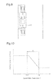
- FIG. 12 is a graph representing changes in the temperature increase amount of the motor through the automatic pulling-in control in correspondence with changes in margin length;
- FIG. 13 is a graph representing the relationship among the predicted temperature Tf 1 , the current temperature T, a determination value Th 1 , an allowable upper limit Tm, and a predetermined value A;
- FIG. 14 is a graph representing the relationship among the predicted temperature Tf 1 , the current temperature T, a temperature increase amount ⁇ Ti, a determination value Th 2 , the allowable upper limit Tm, and a temperature increase amount ⁇ To;
- FIG. 15 is a graph representing the relationship among the predicted temperature Tf 1 , the current temperature T, the temperature increase amount ⁇ Ti, the allowable upper limit Tm, the temperature increase amount ⁇ To, and the predicted temperature Tf 2 ;
- FIG. 16 is a schematic diagram illustrating movement of the host vehicle when the size of a parking area is measured.
- FIG. 17 is a schematic diagram illustrating movement of the host vehicle when the size of a parking area is measured.
- a parking assist device will now be described with reference to FIGS. 1 to 15 .
- the vehicle illustrated in FIG. 1 includes a steering device 2 , which operates steerable wheels 1 to adjust the advancing direction of the vehicle.
- the steering device 2 operates the steerable wheels 1 through steering operation by the driver and has a function of assisting in the driver's steering operation by means of a motor 2 a .
- the steering device 2 is also capable of operating the steerable wheels 1 solely through the motor 2 a , regardless of with or without the driver's steering operation.
- a display panel 3 with a touch sensor and a speaker 4 are provided for the driver seat of the vehicle.
- the display panel 3 displays information regarding driving and is manipulated by the driver for various purposes.
- the speaker 4 provides information regarding driving and alarms the driver using sound.
- Clearance sonars 5 for detecting whether there is an object in the vicinity of the front end (the upper end as viewed in FIG. 1 ) of the vehicle are attached to the front end of the vehicle.
- Ultrasonic sensors 6 for detecting whether there is an object at the corresponding side of the vehicle in the width direction are attached to the side surfaces of the front portion of the vehicle in the width direction (the lateral direction as viewed in the drawing).
- Clearance sonars 7 for detecting whether there is an object in the vicinity of the rear end (the lower end as viewed in the drawing) of the vehicle are attached to the rear end of the vehicle.
- Ultrasonic sensors 8 for detecting whether there is an object at the corresponding side of the vehicle in the width direction are attached to the side surfaces of the rear portion of the vehicle in the width direction.
- the clearance sonars 5 , 7 and the ultrasonic sensors 6 , 8 are connected to an electronic control unit 9 , which performs various types of control on the vehicle.
- the electronic control unit 9 is connected to a shift position sensor 11 for detecting the position of a shift lever 10 , which is manipulated by the driver, an accelerator position sensor 13 for detecting the depression amount of an accelerator pedal 12 , which is depressed by the driver, and a brake switch 15 for detecting whether a brake pedal 14 is depressed by the driver.
- the electronic control unit 9 is also connected to a vehicle wheel speed sensor 16 for detecting the rotation speed of a wheel (such as the steerable wheels 1 ) of the vehicle, an angle sensor 17 for detecting the steering operation angle of the steering device 2 , a temperature sensor 18 for detecting the temperature of a motor 2 a of the steering device 2 , and a yaw rate sensor 19 for detecting the changing rate of the rotation angle when the vehicle turns.
- a vehicle wheel speed sensor 16 for detecting the rotation speed of a wheel (such as the steerable wheels 1 ) of the vehicle
- an angle sensor 17 for detecting the steering operation angle of the steering device 2
- a temperature sensor 18 for detecting the temperature of a motor 2 a of the steering device 2
- a yaw rate sensor 19 for detecting the changing rate of the rotation angle when the vehicle turns.
- the electronic control unit 9 controls the steering device 2 , the display panel 3 , and the speaker 4 and receives signals from the display panel 3 based on manipulation of the display panel 3 by the driver.
- the electronic control unit 9 assists the vehicle to be pulled into or out of the parking area. That is, to pull the vehicle into the parking area, the electronic control unit 9 operates the steerable wheels 1 through automatic pulling-in control, by which the steering device 2 (the motor 2 a ) is automatically operated, instead of using steering operation by the driver. In this manner, the vehicle is assisted to be pulled into the parking area by the electronic control unit 9 .
- the electronic control unit 9 operates the steerable wheels 1 through automatic pulling-out control, by which the steering device 2 (the motor 2 a ) is automatically operated, instead of using steering operation by the driver. In this manner, the vehicle is assisted to be pulled out of the parking area by the electronic control unit 9 .
- pulling-in assist Such assist for the vehicle to pull the vehicle into the parking area (hereinafter, referred to as pulling-in assist) is started if the pulling-in assist for the vehicle with respect to the parking area is requested through manipulation of the display panel 3 by the driver. Also, assist for the vehicle to pull the vehicle out of the parking area (hereinafter, referred to as pulling-out assist) is started if the pulling-out assist for the vehicle with respect to the parking area is requested through manipulation of the display panel 3 by the driver.
- pulling-in assist and the pulling-out assist will each be described generally.
- the electronic control unit 9 instructs the driver to perform measurement starting operation as preparation for size measurement of the parking area through display on the display panel 3 and sound from the speaker 4 .
- the driver is instructed to stop the host vehicle A in a front-facing state at the position represented by the solid lines in FIG. 2 , which is the position beside the parking area P 1 between other vehicles B and C, at which the host vehicle A is located immediately before reaching the zone corresponding to the parking area P 1 after advancing toward the parking area P 1 .
- the driver is instructed to release the brake pedal 14 with the shift lever 10 ( FIG. 1 ) at the drive position.
- the electronic control unit 9 performs a measurement procedure for measuring the size of the parking area P 1 ( FIG. 2 ) using the clearance sonars 5 , 7 and the ultrasonic sensors 6 , 8 .
- the host vehicle A is moved from the position represented by the solid lines in FIG. 2 to the position represented by the long dashed double-short dashed lines, which is the position at which the host vehicle A is located immediately after passing the zone beside the parking area P 1 .
- the electronic control unit 9 monitors signals from the clearance sonars 5 , 7 , the ultrasonic sensors 6 , 8 , the vehicle wheel speed sensor 16 , the angle sensor 17 , and the yaw rate sensor 19 , which are illustrated in FIG. 1 . Then, based on the signals from these sensors, the electronic control unit 9 determines the size of the parking area P 1 and the position of the host vehicle A relative to the parking area P 1 .
- the electronic control unit 9 determines the path by which the target vehicle A will be pulled into the parking area P 1 from the position represented by the long dashed double-short dashed lines in FIG. 2 . Specifically, the electronic control unit 9 stores the size of the host vehicle A, which depends on the specifications of the host vehicle A. Therefore, based on the margin of the size of the parking area P 1 in relation to the size of the host vehicle A, the electronic control unit 9 determines the aforementioned pulling-in path. The electronic control unit 9 then instructs the driver to manipulate the accelerator pedal 12 , the brake pedal 14 , and the shift lever 10 such that the host vehicle A moves along the path determined in the above-described manner.
- the electronic control unit 9 also performs the automatic pulling-in control, by which the steering device 2 (the motor 2 a ) is automatically operated, in correspondence with manipulation by the driver according to instructions.
- the automatic pulling-in control operates the steerable wheels 1 to move the host vehicle A along the aforementioned path solely through actuation of the motor 2 a of the steering device 2 , without steering operation by the driver. In this manner, the host vehicle A is assisted to be pulled into the parking area P 1 .
- not only the steering device 2 is automatically operated as has been described, but also drive force adjustment, brake actuation, and shift position change of the host vehicle A for moving the host vehicle A along the aforementioned path may be automatically performed.
- FIGS. 3 to 8 illustrate an example of operating modes of the steerable wheels 1 according to the automatic pulling-in control for moving the host vehicle A along the aforementioned path.
- the steerable wheels 1 are operated through actuation of the motor 2 a of the steering device 2 such that the host vehicle A moves into the parking area P 1 as indicated by the arrow in FIG. 3 . Then, with the host vehicle A stopped at the position represented in FIG. 4 , the steerable wheels 1 are operated through actuation of the motor 2 a until the steerable wheels 1 become oriented maximally leftward as viewed in the drawing. After changing the orientation of the steerable wheels 1 in this manner, the steerable wheels 1 are operated through actuation of the motor 2 a of the steering device 2 such that the host vehicle A moves in the parking area P 1 as indicated by the arrow in FIG. 4 . Afterwards, with the host vehicle A stopped at the position represented in FIG.
- the steerable wheels 1 are operated through actuation of the motor 2 a until the steerable wheels 1 become oriented maximally rightward as viewed in the drawing. After changing the orientation of the steerable wheels 1 in this manner, the steerable wheels 1 are operated through actuation of the motor 2 a of the steering device 2 such that the host vehicle A moves in the parking area P 1 as indicated by the arrow in FIG. 5 .
- the steerable wheels 1 are operated through actuation of the motor 2 a until the steerable wheels 1 become oriented leftward to a certain extent as viewed in the drawing.
- the steerable wheels 1 are operated through actuation of the motor 2 a of the steering device 2 such that the host vehicle A moves in the parking area P 1 as indicated by the arrow in FIG. 6 .
- the steerable wheels 1 are operated through actuation of the motor 2 a until the steerable wheels 1 become oriented rightward to a certain extent as viewed in the drawing.
- the steerable wheels 1 are operated through actuation of the motor 2 a of the steering device 2 such that the host vehicle A moves in the parking area P 1 as indicated by the arrow in FIG. 7 .
- the host vehicle A is moved to and stopped at the parking position in the parking area P 1 and parking the host vehicle A in the parking area P 1 is thus completed.
- the steerable wheels 1 are operated solely through actuation of the motor 2 a of the steering device 2 without steering operation by the driver. This increases the load on the motor 2 a . In other words, an increased electric current flows in the motor 2 a of the steering device 2 to actuate the motor 2 a . As a result, when the automatic pulling-in control is performed, the motor 2 a of the steering device 2 tends to be heated. Further, when an electric current is supplied to the steering device 2 to actuate the motor 2 a , the electric current flows not only in the motor 2 a but also in a control unit (ECU) for controlling the motor 2 a .
- ECU control unit
- the ECU is thus also heated in the same manner as the motor 2 a when the motor 2 a is heated.
- the amount of temperature increase of the steering device 2 caused by execution of the automatic pulling-in control becomes particularly great when operation for changing the orientation of the steerable wheels 1 through actuation of the motor 2 a is performed with the host vehicle A maintained in a stopped state.
- the load of the motor 2 a is greater and thus tends to become more heated when the operation for changing the orientation of the steerable wheels 1 through actuation of the motor 2 a is performed with the host vehicle A maintained in a stopped state than when the operation for changing the orientation of the steerable wheels 1 through actuation of the motor 2 a is executed with the host vehicle A in a running state.
- the electronic control unit 9 instructs the driver to perform the measurement starting operation as preparation for the size measurement of the parking area through display on the display panel 3 and sound from the speaker 4 .
- the driver is instructed to release the brake pedal 14 with the shift lever ( FIG. 1 ) at the drive position.
- the electronic control unit 9 performs the measurement procedure for measuring the size of the parking area P 1 ( FIG. 9 ) using the clearance sonars 5 , 7 and the ultrasonic sensors 6 , 8 .
- the electronic control unit 9 operates to move the host vehicle A reciprocally in the front-rear direction in such a range that the host vehicle A does not contact obstacles such as the vehicles B, C as indicated by the arrows in FIG. 9 , while monitoring signals from the clearance sonars 5 , 7 and the ultrasonic sensors 6 , 8 , which are illustrated in FIG. 1 .
- the electronic control unit 9 monitors signals from the clearance sonars 5 , 7 , the ultrasonic sensors 6 , 8 , the vehicle wheel speed sensor 16 , the angle sensor 17 , and the yaw rate sensor 19 . Based on the signals from these sensors, the electronic control unit 9 obtains the size of the parking area P 1 and the position of the host vehicle A relative to the parking area P 1 .
- the electronic control unit 9 obtains the path for pulling out the host vehicle A.
- the electronic control unit 9 then instructs the driver to manipulate the accelerator pedal 12 , the brake pedal 14 , and the shift lever 10 such that the host vehicle A moves along the path determined in the above-described manner.
- the electronic control unit 9 also performs the automatic pulling-out control, by which the steering device 2 (the motor 2 a ) is automatically operated, in correspondence with manipulation by the driver according to instructions.
- the automatic pulling-out control operates the steerable wheels 1 to move the host vehicle A along the aforementioned path solely through actuation of the motor 2 a of the steering device 2 , without steering operation by the driver. In this manner, the host vehicle A is assisted to be pulled out of the parking area P 1 .
- the steering device 2 is automatically operated, as has been described, but also drive force adjustment, brake actuation, and shift position change of the host vehicle A for moving the host vehicle A along the aforementioned path may be automatically performed.
- the motor 2 a is actuated to operate the steerable wheels 1 in the manner opposite to the manner illustrated in FIGS. 3 to 8 in which the steerable wheels 1 are operated such that the host vehicle A is pulled into the parking area P 1 .
- the steerable wheels 1 are operated solely through actuation of the motor 2 a of the steering device 2 without steering operation by the driver, as in the above-described automatic pulling-in control.
- the load on the motor 2 a is thus increased.
- the motor 2 a and the ECU of the steering device 2 tend to become heated.
- the temperature increase amount of the motor 2 a and that of the ECU increase particularly when operation for changing the orientation of the steerable wheels 1 through actuation of the motor 2 a is performed with the host vehicle A maintained in a stopped state in the automatic pulling-out control.
- the automatic pulling-in control may be prohibited from starting if the temperature of the motor 2 a is higher than or equal to a determination value before the automatic pulling-in control is started.
- the execution frequency of the automatic pulling-in control may be increased by setting the determination value to a high value to increase.
- the automatic pulling-out control is performed subsequent to execution of the automatic pulling-in control to start over the parking operation of the vehicle after the automatic pulling-in control is started, unfavorable temperature increase of the motor 2 a and the ECU may be caused.
- Such temperature increase of the motor 2 a and the ECU, which occurs after the automatic pulling-in control is started makes it difficult to maintain the temperatures of the motor 2 a and the ECU each at a sufficiently low value.
- the temperature of the motor 2 a may be monitored after the automatic pulling-in control is started. In this case, if the temperature of the motor 2 a cannot be maintained at a sufficiently low value, the automatic pulling-in or pulling-out control may be suspended without completion to prevent temperature increase of the motor 2 a and the ECU. However, if the automatic pulling-in or pulling-out control is suspended before completion, the driver must continue to pull the host vehicle A into or out of the parking area P 1 through manual operation of the steering wheel afterwards. In this case, if the driver is not sufficiently skilled, the host vehicle A cannot be properly pulled into or out of the parking area in some cases.
- the parking assist device of the present embodiment performs the procedures (D 1 ) and (D 2 ), as will be described, through the electronic control unit 9 .
- the electronic control unit 9 functions as a control section when performing the procedure (D 2 ).
- the allowable upper limit Tm may be the maximum value of a temperature range of the motor 2 a that prevents hampering of operation of the motor 2 a.
- the electronic control unit 9 constantly monitors the electric current flowing in the motor 2 a regardless of whether the automatic pulling-in or pulling-out control is in execution. As a procedure for restraining temperature increase of the motor 2 a , the electronic control unit 9 performs an electric current limiting procedure for limiting the electric current flowing in the motor 2 a to a value less than a limit value such that the electric current does not become greater than or equal to the limit value.
- the electric current limiting procedure limits the electric current flowing in the motor 2 a to the limit value when the electric current becomes greater than or equal to the limit value. This facilitates maintenance of the temperature of the motor 2 a and the temperature of the ECU of the steering device 2 each at a sufficiently low value.
- the electronic control unit 9 changes the aforementioned limit value, which is used in the electric current limiting procedure, in correspondence with the current temperature T of the motor 2 a.
- FIG. 10 is a graph representing changes in the limit value in correspondence with changes in the current temperature T of the motor 2 a .
- the limit value is changed as represented by the solid line in the graph as the current temperature T of the motor 2 a increases. That is, when the current temperature T is high, or, for example, higher than the determination value Th 1 , the limit value is gradually decreased from the normal value as the current temperature T is increased. The limit value then becomes minimized when the current temperature T becomes higher than or equal to the aforementioned allowable upper limit Tm, which is higher than the determination value Th 1 .
- the parking assist device starts the automatic pulling-in control
- the above-described procedures (D 1 ) and (D 2 ) are performed through the electronic control unit 9 .
- the temperature of the motor 2 a may become higher than or equal to the allowable upper limit Tm. In this case, to avoid such temperature increase, the automatic pulling-in or pulling-out control that is currently in execution may have to be suspended.
- the automatic pulling-in control is prohibited from starting in the aforementioned state, suspension of the automatic pulling-in or pulling-out control due to temperature increase of the motor 2 a after start of the automatic pulling-in control is avoided. Also, even in the aforementioned state, the automatic pulling-in control is permitted to start as long as the predicted temperature Tf 2 is less than the allowable upper limit Tm. This increases the execution frequency of the automatic pulling-in control as much as possible.
- FIG. 11 is a flowchart representing an automatic pulling-in control routine for selectively prohibiting and permitting execution of the automatic pulling-in control based on the aforementioned predicted temperature Tf 2 .
- the automatic pulling-in control routine is periodically performed through the electronic control unit 9 in an interrupting manner at predetermined time intervals.
- the electronic control unit 9 determines whether the automatic pulling-in control is currently suspended as Step 101 (S 101 ) of the routine. If a positive determination is made in this step, the electronic control unit 9 suspends the automatic pulling-in control routine. In contrast, if a negative determination is made in S 101 , the electronic control unit 9 performs S 102 . As S 102 , the electronic control unit 9 determines whether a command for starting pulling-in assist for the vehicle with respect to a parking area has been generated. The command for starting the pulling-in assist is generated through manipulation of the display panel 3 by the driver to start the pulling-in assist. When a negative determination is made in S 102 , the electronic control unit 9 suspends the automatic pulling-in control routine. If a positive determination is made in S 102 , the electronic control unit 9 performs S 103 .
- the electronic control unit 9 determines whether size measurement of the parking area P 1 has been complete. If a negative determination is made in this step, S 104 is performed. As S 104 , the electronic control unit 9 executes a measurement procedure for measuring the size of the parking area P 1 . Specifically, on condition that the driver has accomplished the measurement starting operation for the pulling-in or pulling-out assist, the electronic control unit 9 performs the aforementioned measurement procedure to measure the size of the parking area P 1 through the measurement procedure. After the size measurement of the parking area P 1 is completed through the measurement procedure, a positive determination is made in S 103 and S 105 is performed.
- the S 105 and S 109 to S 113 correspond to the above-described procedures (D 1 ) and (D 2 ).
- the automatic pulling-in control is prohibited from starting (S 112 ) or permitted to start (S 113 ).
- the electronic control unit 9 suspends the automatic pulling-in control routine. If the automatic pulling-in control is permitted to start, the electronic control unit 9 performs the automatic pulling-in control as S 114 and then suspends the automatic pulling-in control routine.
- the S 105 and the subsequent steps will hereafter be described in detail.
- the electronic control unit 9 calculates the temperature increase amount ⁇ Ti of the motor 2 a of the steering device 2 , which is caused by execution of the automatic pulling-in control. Specifically, as the difference between the size of the parking area P 1 and the size of the host vehicle A, the electronic control unit 9 obtains the margin length ⁇ L, which is the value obtained by subtracting the length (the full length) of the host vehicle A in the front-rear direction from the length of the parking area P 1 in the front-rear direction of the host vehicle A (the length in the up-down direction as viewed in FIGS. 2 to 8 ).
- the temperature increase amount ⁇ Ti is calculated based on the margin length ⁇ L (which corresponds to the size of the parking area P 1 ) with reference to a first map, which defines the relationship between the margin length ⁇ L and the temperature increase amount of the motor 2 a.
- the solid line in FIG. 12 represents a manner in which the temperature increase amount ⁇ Ti, which is calculated referring to the aforementioned first map, decreases as the margin length ⁇ L increases. As the margin length ⁇ L increases, the aforementioned temperature increase amount ⁇ Ti decreases as represented by the solid line in FIG. 12 .
- the S 106 to S 108 for further increasing the execution frequency of the automatic pulling-in control are performed.
- the S 106 to S 108 are performed through the electronic control unit 9 in the manner described below.
- the electronic control unit 9 obtains the predicted temperature Tf 1 of the motor 2 a in a case in which the automatic pulling-in control is performed. Specifically, the electronic control unit 9 adds the temperature increase amount ⁇ Ti to the current temperature T, thus determining the predicted temperature Tf 1 of the motor 2 a in a case in which the host vehicle A is completely pulled into the parking area through the automatic pulling-in control. Then, in S 107 , the electronic control unit 9 obtains the value obtained by subtracting the predetermined value A from the allowable upper limit Tm as the determination value Th 1 . The electronic control unit 9 then determines whether the predicted temperature Tf 1 is higher than or equal to the determination value Th 1 in S 108 .
- section (a) corresponds to a positive determination in S 108 and represents the relationship among the predicted temperature Tf 1 , the current temperature T, the determination value Th 1 , the allowable upper limit Tm, and the predetermined value A.
- Section (b) corresponds to a negative determination in S 108 and represents the relationship among the predicted temperature Tf 1 , the current temperature T, the determination value Th 1 , the allowable upper limit Tm, and the predetermined value A.
- S 113 is performed directly without performing S 109 to S 112 of FIG. 11 .
- S 113 is performed to permit the automatic pulling-in control to start not only when the predicted temperature Tf 2 is less than the allowable upper limit Tm but also when the predicted temperature Tf 1 is less than the determination value Th 1 , which is lower than the allowable upper limit Tm.
- the predetermined value A which is used to determine the determination value Th 1 , may be a fixed value determined in advance through tests or the like, which is, for example, a temperature increase amount of the motor 2 a caused by execution of the automatic pulling-out control under the most unfavorable temperature increase of the motor 2 a.
- S 109 is performed.
- the electronic control unit 9 calculates the temperature increase amount ⁇ To of the motor 2 a caused by execution of the automatic pulling-out control.
- the smaller the margin length ⁇ L the greater the number of times the steerable wheels 1 are operated to change the orientation of the steerable wheels 1 with the host vehicle A maintained in a stopped state in the path for pulling the host vehicle A out of the parking area P 1 .
- the greater the number of times such operation of the steerable wheels 1 is performed the greater the load on the motor 2 a for moving the host vehicle A along the aforementioned path through the automatic pulling-out control.
- the temperature increase amount of the motor 2 a caused by execution of the automatic pulling-out control thus becomes correspondingly greater.
- the temperature increase amount ⁇ To is calculated based on the margin length ⁇ L (which corresponds to the size of the parking area P 1 ) with reference to a second map, which defines the relationship between the margin length ⁇ L and the temperature increase amount of the motor 2 a.
- the broken line in FIG. 12 represents the manner in which the temperature increase amount ⁇ To, which is calculated referring to the aforementioned second map, decreases as the margin length ⁇ L increases. As the margin length ⁇ L increases, the temperature increase amount ⁇ Ti decreases as represented by the broken line in FIG. 12 .
- the broken line (the temperature increase amount ⁇ To) is located lower (in a lower range) than the solid line (the temperature increase amount ⁇ Ti), as viewed in the graph. This is caused by the fact that pulling the host vehicle A out of the parking area P 1 is easier than pulling the host vehicle A into the parking area P 1 .
- the steerable wheels 1 are operated a fewer number of times to change the orientation of the steerable wheels 1 with the host vehicle A maintained in a stopped state when the host vehicle A is pulled into the parking area P 1 than when the host vehicle A is pulled out of the parking area P 1 .
- the electronic control unit 9 obtains the determination value Th 1 as the value obtained by subtracting the temperature increase amount ⁇ To from the allowable upper limit Tm. Then, as S 111 , the electronic control unit 9 determines whether the predicted temperature Tf 1 is less than the determination value Th 2 , or, in other words, the expression described below is satisfied. Tf1 ⁇ Th2 (1)
- Section (a) of FIG. 14 represents the relationship among the predicted temperature Tf 1 , the current temperature T, the temperature increase amount ⁇ Ti, the determination value Th 2 , the allowable upper limit Tm, and the temperature increase amount ⁇ To corresponding to a positive determination in S 110 .
- Section (b) of FIG. 14 represents the relationship among the predicted temperature Tf 1 , the current temperature T, the temperature increase amount ⁇ Ti, the determination value Th 2 , the allowable upper limit Tm, and the temperature increase amount ⁇ To corresponding to a negative determination in S 110 .
- Tf 1 T+ ⁇ Ti
- Th 2 Tm ⁇ To
- T+ ⁇ Ti+ ⁇ To Tf 2 (4)
- Section (a) of FIG. 15 corresponds to a case in which the expression (5) is satisfied and represents the relationship among the predicted temperature Tf 1 , the current temperature T, the temperature increase amount ⁇ Ti, the allowable upper limit Tm, the temperature increase amount ⁇ To, and the predicted temperature Tf 2 .
- Section (b) of FIG. 15 corresponds to a case in which the expression (5) is not satisfied and represents the relationship among the predicted temperature Tf 1 , the current temperature T, the temperature increase amount ⁇ Ti, the allowable upper limit Tm, and the temperature increase amount ⁇ To.
- Step S 111 determination of S 111 whether the predicted temperature Tf 1 is less than the determination value Th 2 corresponds to determination whether the predicted temperature Tf 2 is less than the allowable upper limit Tm.
- a negative determination made in Step S 111 indicates that the predicted temperature Tf 2 is higher than or equal to the allowable upper limit Tm.
- the electronic control unit 9 prohibits the automatic pulling-in control from starting as S 112 and then suspends the automatic pulling-in control routine.
- a positive determination made in Step S 111 indicates that the predicted temperature Tf 2 is less than the allowable upper limit Tm.
- the electronic control unit 9 permits the automatic pulling-in control to start as S 113 and performs the automatic pulling-in control as S 114 . The electronic control unit 9 then suspends the automatic pulling-in control routine.
- the present embodiment as described above has the following advantages.
- the procedure for further increasing the execution frequency of the automatic pulling-in control is performed. That is, based on the current temperature T and the temperature increase amount ⁇ Ti of the motor 2 a , the predicted temperature Tf 1 of the motor 2 a in a case in which the automatic pulling-in control is executed is determined. If the predicted temperature Tf 1 is higher than or equal to the determination value Th 1 , which is lower than the allowable upper limit Tm by the predetermined value A, the automatic pulling-in control is permitted to start.
- the automatic pulling-in control is permitted to start not only when the predicted temperature Tf 2 is less than the allowable upper limit Tm but also when the predicted temperature Tf 1 is less than the determination value Th 1 , which is lower than the allowable upper limit Tm. This further increases the execution frequency of the automatic pulling-in control.
- the electronic control unit 9 may monitor the operating state of the steering device 2 (the motor 2 a ) while executing the automatic pulling-in control.
- the electronic control unit 9 may provide a corresponding alarm by means of the display panel 3 or the speaker 4 .
- the display panel 3 and the speaker 4 each function as an alarming section when providing the alarm.
- the actual operating state of the steering device 2 brought about by the automatic pulling-in control does not necessarily correspond to the operating state with reference to which the temperature increase amount ⁇ Ti is defined, which is the expected operating state.
- the temperature of the steering device 2 may increase by an amount exceeding the temperature increase amount ⁇ Ti.
- the operating state of the motor 2 a indicates that the temperature of the motor 2 a is likely to increase by an amount exceeding the temperature increase amount ⁇ Ti through execution of the automatic pulling-in control
- a corresponding alarm is provided through the display panel 3 or the speaker 4 . The alarm allows the driver to suspend the automatic pulling-in control and manually pull the host vehicle A into the parking area P 1 .
- the temperature increase amount of the motor 2 a caused by execution of the automatic pulling-in control is influenced by variation in pneumatic pressure of the vehicle wheels or variation in the total weight of the host vehicle A caused by varying numbers of occupants. Information including such variations in the wheel pneumatic pressure and the total weight of the host vehicle A may be input through manipulation of the display panel 3 by the driver and used to calculate the temperature increase amount ⁇ Ti by the electronic control unit 9 . In this case, the obtained temperature increase amount ⁇ Ti becomes more accurate.
- the temperature increase amounts ⁇ Ti, ⁇ To may be calculated using expressions as will be described. That is, the path for pulling the host vehicle A into the parking area P 1 is determined. Then, the electric power consumed by the motor 2 a for executing the automatic control of the steering device 2 to move the host vehicle A along the determined path and the temperature increase amount (which corresponds to the temperature increase amount ⁇ Ti) of the motor 2 a caused by consumption of the electric power are calculated using an expression. Also, the path for pulling the host vehicle A out of the parking area P 1 is determined.
- the electric power consumed by the motor 2 a for executing the automatic control of the steering device 2 to move the host vehicle A along the determined path and the temperature increase amount (which corresponds to the temperature increase amount ⁇ To) of the motor 2 a caused by consumption of the electric power are calculated using an expression.
- the automatic pulling-in control is used to pull the host vehicle A into the parking area P 1 in a parallel parking, in which the parking area P 1 of the host vehicle A is arranged between the other vehicles B and C in the front-rear direction of the host vehicle A.
- the automatic pulling-out control is used to pull the host vehicle A out of the parking area P 1 in the same manner.
- use of the control is not restricted to these cases.
- the automatic pulling-in control may be used to pull the host vehicle A into the parking area P 1 in a perpendicular parking, in which the parking area P 1 of the host vehicle A is arranged between the other vehicles B and C in the width direction of the host vehicle A.
- the automatic pulling-out control may be used to pull the host vehicle A out of the parking area P 1 in the same manner.
- the electronic control unit 9 provides an instruction to the driver to perform the measurement starting operation as preparation for size measurement of the parking area P 1 in the manner described below. That is, the driver is instructed to stop the host vehicle A in a front-facing state at the position represented by the solid lines in FIG. 16 , which is the position in front of the parking area P 1 between the other vehicles B and C at which the host vehicle A is located immediately before reaching the zone corresponding to the parking area P 1 after advancing toward the parking area P 1 . Then, with the host vehicle A stopped at the position, the driver is instructed to release the brake pedal 14 with the shift lever 10 at the drive position.
- the electronic control unit 9 performs the measurement procedure for measuring the size of the parking area P 1 .
- the host vehicle A is moved from the position represented by the solid lines to the position represented by the long dashed double-short dashed lines, which is the position at which the host vehicle A is located immediately after passing the zone beside the parking area P 1 .
- the electronic control unit 9 monitors signals from the clearance sonars 5 , 7 , the ultrasonic sensors 6 , 8 , the vehicle wheel speed sensor 16 , the angle sensor 17 , and the yaw rate sensor 19 .
- the electronic control unit 9 obtains the size of the parking area P 1 and the position of the host vehicle A relative to the parking area P 1 . Subsequently, the electronic control unit 9 obtains a path for pulling the host vehicle A into the parking area P 1 from the position represented by the long dashed double-short dashed lines based on the difference between the size of the parking area P 1 and the size of the host vehicle A. The electronic control unit 9 then performs automatic control of the steering device 2 such that the host vehicle A moves along the determined path.
- the electronic control unit 9 When the pulling-out assist is started by the parking assist device, the electronic control unit 9 provides an instruction to the driver to perform the measurement starting operation as preparation for size measurement of the parking area P 1 in the manner described below. That is, with the host vehicle A maintained in the parking area P 1 as represented by the solid lines in FIG. 17 , the driver is instructed to release the brake pedal 14 with the shift lever 10 at the drive position. On condition that the driver has accomplished the above-described measurement starting operation, the electronic control unit 9 performs the measurement procedure for measuring the size of the parking area P 1 . In the measurement procedure, the host vehicle A is operated to move reciprocally in the front-rear direction in such a range that the host vehicle A does not contact obstacles.
- the electronic control unit 9 monitors signals from the clearance sonars 5 , 7 , the ultrasonic sensors 6 , 8 , the vehicle wheel speed sensor 16 , the angle sensor 17 , and the yaw rate sensor 19 . Based on the signals from these sensors, the electronic control unit 9 obtains the size of the parking area P 1 and the position of the host vehicle A relative to the parking area P 1 . Subsequently, based on the difference between the size of the parking area P 1 and the size of the host vehicle A, the electronic control unit 9 obtains a path for pulling the host vehicle A out of the parking area P 1 , in which the host vehicle A is parked. The electronic control unit 9 then performs automatic control of the steering device 2 such that the host vehicle A moves along the determined path.
- the temperature of the ECU for controlling the motor 2 a may be employed instead of the temperature of the motor 2 a .
- the temperature sensor 18 detects the temperature of the ECU.
Abstract
When starting automatic pulling-in control, an electronic control unit calculates a temperature increase amount ΔTi of a motor caused by the execution of the automatic pulling-in control and a temperature increase amount ΔTo of the motor caused by the execution of automatic pulling-out control. Based on the current temperature of the motor, the temperature increase amount ΔTi, and the temperature increase amount ΔTo, the electronic control unit obtains a predicted temperature of the motor of a case in which the automatic pulling-out control is executed subsequent to the automatic pulling-in control. When the predicted temperature is lower than an allowable upper limit, starting of the automatic pulling-in control is permitted. When the predicted temperature is higher than or equal to the allowable upper limit, starting of the automatic pulling-in control is prohibited.
Description
This application is a national phase application of International Application No. PCT/JP2013/065619, filed Jun. 5, 2013, the content of which is incorporated herein by reference.
The present invention relates to a parking assist device.
Some vehicles such as automobiles are known to be equipped with a parking assist device. The parking assist device assists the vehicle when the vehicle is pulled into (is parked in) a certain parking area and pulled out of (starts from) the parking area.
To pull a vehicle into or out of a parking area, the parking assist device operates the steerable wheels of the vehicle through automatic control of the steering device, instead of using steering operation by the driver. Specifically, the vehicle is pulled into the parking area through automatic pulling-in control by which the steering device is automatically operated. The vehicle is pulled out of the parking area through automatic pulling-out control by which the steering device is automatically operated. Through such automatic pulling-in and pulling-out controls, the steerable wheels are operated to pull the vehicle into or out of the parking area without steering operation by the driver. In this manner, the vehicle is assisted to be pulled into or out of the parking area.
When a vehicle is assisted to be pulled into or out of a parking area by a parking assist device, the steerable wheels are operated solely by the power of the actuator, such as a motor, of the steering device through the automatic pulling-in or pulling-out control without depending on any steering operation by the driver. This increases the load acting on the steering device when the automatic pulling-in or pulling-out control is performed compared to usual times. The temperature of the steering device thus tends to increase. As a result, in a vehicle having such a parking assist device, the parking assist device must have improved heat resistance.
In this regard, Patent Document 1 describes a configuration in which automatic pulling-in control is prohibited from starting if the temperature of the steering device is higher than the maximum value of a first temperature range. As a result, even if the temperature of the steering device increases after the automatic pulling-in control is started, the temperature of the steering device is maintained at a sufficiently low value. This restrains cost increase. The maximum value of the first temperature range may be set to a high value such that the condition for executing the automatic pulling-in control is relaxed to increase the execution frequency of the automatic pulling-in control.
- Patent Document 1: Japanese Laid-Open Patent Publication No. 2010-228591
In the configuration in which the automatic pulling-in control is prohibited from starting when the temperature of the steering device is higher than the maximum value of the first temperature range as described in Patent Document 1, the execution frequency of the automatic pulling-in control may be increased by setting the maximum value to a high value.
However, if the maximum value of the first temperature range is set to a high value as has been described, unfavorable temperature increase may occur in the steering device after automatic pulling-control is started. In such a case, it is difficult to maintain the temperature of the steering device at a sufficiently low value after the automatic pulling-in control is started in the following situations. That is, if the automatic pulling-out control is performed subsequent to execution of the automatic pulling-in control to start over the parking operation of the vehicle after the automatic pulling-in control is started, the temperature of the steering device is increased also in the automatic pulling-out control, which is performed subsequent to execution of the automatic pulling-in control. This makes it difficult to maintain the temperature of the steering device at a sufficiently low value.
To avoid this, the technique disclosed in Patent Document 1 suspends the automatic pulling-in or pulling-out control is suspended if the temperature of the steering device becomes higher than the maximum value of a second temperature range, which is set to a range lower than the maximum value of the first temperature range, after the automatic pulling-in control is started. In this case, when the temperature of the steering device becomes higher than the maximum value of the second temperature range after the automatic pulling-in control is started, the automatic pulling-in or pulling-out control that is currently in execution is suspended. The temperature of the steering device thus can be maintained at a sufficiently low value.
However, if the currently executed automatic pulling-in or pulling-out control is suspended before completion, or, in other words, pulling the vehicle into or out of the parking area through the corresponding automatic pulling-in or pulling-out control is incomplete, the problem described below occurs. That is, after the automatic pulling-in or pulling-out control is suspended before completion, the driver must manually manipulate the steering wheel to continue to pull the vehicle into or out of the parking area. If the driver is not sufficiently skilled, the vehicle cannot be properly pulled into or out of the parking area in some cases.
Accordingly, it is an objective of the present invention to provide a parking assist device capable of increasing execution frequency of automatic pulling-in control as much as possible while avoiding suspension of automatic pulling-in or pulling-out control caused by temperature increase of a steering device after the automatic pulling-in control is started.
Means for achieving the above objective and advantages thereof will now be discussed.
To achieve the foregoing objective and in accordance with one aspect of the present invention, a parking assist device is provided that is capable of performing automatic pulling-in control to automatically operate a steering device to assist a vehicle to be pulled into a parking area and automatic pulling-out control to automatically operate the steering device to assist the vehicle to be pulled out of the parking area. When the automatic pulling-in control is started, a temperature increase amount ΔTi of the steering device caused by execution of the automatic pulling-in control is calculated, and a temperature increase amount ΔTo of the steering device caused by execution of the automatic pulling-out control is calculated. Based on a current temperature T of the steering device, the temperature increase amount ΔTi, and the temperature increase amount ΔTo, a predicted temperature Tf2 of the steering device of a case in which the automatic pulling-out control is performed subsequent to execution of the automatic pulling-in control is obtained. The automatic pulling-in control is permitted to start if the predicted temperature Tf2 is less than an allowable upper limit Tm. The automatic pulling-in control is prohibited from starting if the predicted temperature Tf2 is higher than or equal to the allowable upper limit Tm.
Thus, start of the automatic pulling-in control is avoided in a state in which the temperature of the steering device is likely to become higher than or equal to the allowable upper limit Tm if the automatic pulling-out control is performed subsequent to execution of the automatic pulling-in control to start over the parking operation of the vehicle. If the automatic pulling-in control is started in the aforementioned state, the temperature of the steering device may become higher than or equal to the allowable upper limit Tm. In this case, to avoid such temperature increase, the automatic pulling-in or pulling-out control that is currently in execution may have to be suspended. However, since the automatic pulling-in control is prohibited from starting in the aforementioned state, suspension of the automatic pulling-in or pulling-out control due to temperature increase of the steering device after start of the automatic pulling-in control is avoided. Also, even in the aforementioned state, the automatic pulling-in control is permitted to start as long as the predicted temperature Tf2 is less than the allowable upper limit Tm. This increases the execution frequency of the automatic pulling-in control as much as possible.
Prior to determination whether the predicted temperature Tf2 is less than the allowable upper limit Tm, the control section may perform the following procedure. That is, the control section may obtain a predicted temperature Tf1 of a case in which the automatic pulling-in control is performed based on the current temperature T and the temperature increase amount ΔTi of the steering device, and permit the automatic pulling-in control to start if the predicted temperature Tf1 is less than a determination value Th1, which is lower than the allowable upper limit Tm. In this case, the automatic pulling-in control is permitted to start not only when the predicted temperature Tf2 is less than the allowable upper limit Tm but also when the predicted temperature Tf1 is less than the determination value Th1, which is lower than the allowable upper limit Tm. This further increases the execution frequency of the automatic pulling-in control.
The calculating section may be configured to calculate the temperature increase amount ΔTi and the temperature increase amount ΔTo based on the size of the parking area.
The calculating section may be configured to: calculate the temperature increase amount ΔTi based on the difference between the size of the parking area and the size of the vehicle with reference to a first map; and calculate the temperature increase amount ΔTo based on the difference between the size of the parking area and the size of the vehicle with reference to a second map.
Further, the calculating section may be configured to: calculate the temperature increase amount ΔTi based on a pulling-in path used to assist the vehicle to be pulled into the parking area through the automatic pulling-in control; and calculate the temperature increase amount ΔTo based on a pulling-out path used to assist the vehicle to be pulled out of the parking area through the automatic pulling-out control.
The control section may also be configured to: monitor an operating state of the steering device when performing the automatic pulling-in control; and provide a corresponding alarm through an alarming section when determining that the operating state of the steering device corresponds to a state in which the temperature of the steering device is likely to increase by an amount exceeding the temperature increase amount ΔTi during the execution of the automatic pulling-in control. The actual operating state of the steering device brought about by the automatic pulling-in control does not necessarily agree with an operating state that will cause the temperature increase amount ΔTi. That is, the actual operating state does not necessarily agree with a predicted operating state. If the actual operating state does not agree with to the predicted operating state, the temperature of the steering device may increase by an amount exceeding the temperature increase amount ΔTi. However, if the operating state of the steering device indicates that the temperature of the steering device is likely to increase by an amount exceeding the temperature increase amount ΔTi through execution of the automatic pulling-in control, the alarming section is operated to provide a corresponding alarm. The alarm allows the driver to suspend the automatic pulling-in control and manually pull the vehicle into the parking area.
A parking assist device according to one embodiment will now be described with reference to FIGS. 1 to 15 .
The vehicle illustrated in FIG. 1 includes a steering device 2, which operates steerable wheels 1 to adjust the advancing direction of the vehicle. The steering device 2 operates the steerable wheels 1 through steering operation by the driver and has a function of assisting in the driver's steering operation by means of a motor 2 a. The steering device 2 is also capable of operating the steerable wheels 1 solely through the motor 2 a, regardless of with or without the driver's steering operation. For the driver seat of the vehicle, a display panel 3 with a touch sensor and a speaker 4 are provided. The display panel 3 displays information regarding driving and is manipulated by the driver for various purposes. The speaker 4 provides information regarding driving and alarms the driver using sound.
Clearance sonars 5 for detecting whether there is an object in the vicinity of the front end (the upper end as viewed in FIG. 1 ) of the vehicle are attached to the front end of the vehicle. Ultrasonic sensors 6 for detecting whether there is an object at the corresponding side of the vehicle in the width direction are attached to the side surfaces of the front portion of the vehicle in the width direction (the lateral direction as viewed in the drawing). Clearance sonars 7 for detecting whether there is an object in the vicinity of the rear end (the lower end as viewed in the drawing) of the vehicle are attached to the rear end of the vehicle. Ultrasonic sensors 8 for detecting whether there is an object at the corresponding side of the vehicle in the width direction are attached to the side surfaces of the rear portion of the vehicle in the width direction.
The clearance sonars 5, 7 and the ultrasonic sensors 6, 8 are connected to an electronic control unit 9, which performs various types of control on the vehicle. The electronic control unit 9 is connected to a shift position sensor 11 for detecting the position of a shift lever 10, which is manipulated by the driver, an accelerator position sensor 13 for detecting the depression amount of an accelerator pedal 12, which is depressed by the driver, and a brake switch 15 for detecting whether a brake pedal 14 is depressed by the driver. The electronic control unit 9 is also connected to a vehicle wheel speed sensor 16 for detecting the rotation speed of a wheel (such as the steerable wheels 1) of the vehicle, an angle sensor 17 for detecting the steering operation angle of the steering device 2, a temperature sensor 18 for detecting the temperature of a motor 2 a of the steering device 2, and a yaw rate sensor 19 for detecting the changing rate of the rotation angle when the vehicle turns.
The electronic control unit 9 controls the steering device 2, the display panel 3, and the speaker 4 and receives signals from the display panel 3 based on manipulation of the display panel 3 by the driver. When the vehicle is pulled into (parked in) a predetermined parking area or pulled out of (started from) the parking area, the electronic control unit 9 assists the vehicle to be pulled into or out of the parking area. That is, to pull the vehicle into the parking area, the electronic control unit 9 operates the steerable wheels 1 through automatic pulling-in control, by which the steering device 2 (the motor 2 a) is automatically operated, instead of using steering operation by the driver. In this manner, the vehicle is assisted to be pulled into the parking area by the electronic control unit 9. Also, to pull the vehicle out of the parking area, the electronic control unit 9 operates the steerable wheels 1 through automatic pulling-out control, by which the steering device 2 (the motor 2 a) is automatically operated, instead of using steering operation by the driver. In this manner, the vehicle is assisted to be pulled out of the parking area by the electronic control unit 9.
Such assist for the vehicle to pull the vehicle into the parking area (hereinafter, referred to as pulling-in assist) is started if the pulling-in assist for the vehicle with respect to the parking area is requested through manipulation of the display panel 3 by the driver. Also, assist for the vehicle to pull the vehicle out of the parking area (hereinafter, referred to as pulling-out assist) is started if the pulling-out assist for the vehicle with respect to the parking area is requested through manipulation of the display panel 3 by the driver. Hereinafter, the pulling-in assist and the pulling-out assist will each be described generally.
[Pulling-in Assist]
After the pulling-in assist is started, the electronic control unit 9 instructs the driver to perform measurement starting operation as preparation for size measurement of the parking area through display on the display panel 3 and sound from the speaker 4. For example, the driver is instructed to stop the host vehicle A in a front-facing state at the position represented by the solid lines in FIG. 2 , which is the position beside the parking area P1 between other vehicles B and C, at which the host vehicle A is located immediately before reaching the zone corresponding to the parking area P1 after advancing toward the parking area P1. Then, with the host vehicle A stopped at the position, the driver is instructed to release the brake pedal 14 with the shift lever 10 (FIG. 1 ) at the drive position.
On condition that the driver has accomplished the above-described measurement starting operation, the electronic control unit 9 performs a measurement procedure for measuring the size of the parking area P1 (FIG. 2 ) using the clearance sonars 5, 7 and the ultrasonic sensors 6, 8. In the measurement procedure, the host vehicle A is moved from the position represented by the solid lines in FIG. 2 to the position represented by the long dashed double-short dashed lines, which is the position at which the host vehicle A is located immediately after passing the zone beside the parking area P1. While the host vehicle A is moved from the position represented by the solid lines to the position represented by the long dashed double-short dashed lines, the electronic control unit 9 monitors signals from the clearance sonars 5, 7, the ultrasonic sensors 6, 8, the vehicle wheel speed sensor 16, the angle sensor 17, and the yaw rate sensor 19, which are illustrated in FIG. 1 . Then, based on the signals from these sensors, the electronic control unit 9 determines the size of the parking area P1 and the position of the host vehicle A relative to the parking area P1.
Then, based on the size of the parking area P1, the electronic control unit 9 determines the path by which the target vehicle A will be pulled into the parking area P1 from the position represented by the long dashed double-short dashed lines in FIG. 2 . Specifically, the electronic control unit 9 stores the size of the host vehicle A, which depends on the specifications of the host vehicle A. Therefore, based on the margin of the size of the parking area P1 in relation to the size of the host vehicle A, the electronic control unit 9 determines the aforementioned pulling-in path. The electronic control unit 9 then instructs the driver to manipulate the accelerator pedal 12, the brake pedal 14, and the shift lever 10 such that the host vehicle A moves along the path determined in the above-described manner. The electronic control unit 9 also performs the automatic pulling-in control, by which the steering device 2 (the motor 2 a) is automatically operated, in correspondence with manipulation by the driver according to instructions. The automatic pulling-in control operates the steerable wheels 1 to move the host vehicle A along the aforementioned path solely through actuation of the motor 2 a of the steering device 2, without steering operation by the driver. In this manner, the host vehicle A is assisted to be pulled into the parking area P1. In such assist for the host vehicle A to pull the host vehicle A into the parking area P1, not only the steering device 2 is automatically operated as has been described, but also drive force adjustment, brake actuation, and shift position change of the host vehicle A for moving the host vehicle A along the aforementioned path may be automatically performed.
In the automatic pulling-in control, the steerable wheels 1 are operated through actuation of the motor 2 a of the steering device 2 such that the host vehicle A moves into the parking area P1 as indicated by the arrow in FIG. 3 . Then, with the host vehicle A stopped at the position represented in FIG. 4 , the steerable wheels 1 are operated through actuation of the motor 2 a until the steerable wheels 1 become oriented maximally leftward as viewed in the drawing. After changing the orientation of the steerable wheels 1 in this manner, the steerable wheels 1 are operated through actuation of the motor 2 a of the steering device 2 such that the host vehicle A moves in the parking area P1 as indicated by the arrow in FIG. 4 . Afterwards, with the host vehicle A stopped at the position represented in FIG. 5 , the steerable wheels 1 are operated through actuation of the motor 2 a until the steerable wheels 1 become oriented maximally rightward as viewed in the drawing. After changing the orientation of the steerable wheels 1 in this manner, the steerable wheels 1 are operated through actuation of the motor 2 a of the steering device 2 such that the host vehicle A moves in the parking area P1 as indicated by the arrow in FIG. 5 .
Subsequently, with the host vehicle A stopped at the position represented in FIG. 6 , the steerable wheels 1 are operated through actuation of the motor 2 a until the steerable wheels 1 become oriented leftward to a certain extent as viewed in the drawing. After changing the orientation of the steerable wheels 1 in this manner, the steerable wheels 1 are operated through actuation of the motor 2 a of the steering device 2 such that the host vehicle A moves in the parking area P1 as indicated by the arrow in FIG. 6 . Afterwards, with the host vehicle A stopped at the position represented in FIG. 7 , the steerable wheels 1 are operated through actuation of the motor 2 a until the steerable wheels 1 become oriented rightward to a certain extent as viewed in the drawing. After changing the orientation of the steerable wheels 1 in this manner, the steerable wheels 1 are operated through actuation of the motor 2 a of the steering device 2 such that the host vehicle A moves in the parking area P1 as indicated by the arrow in FIG. 7 . As a result, as illustrated in FIG. 8 , the host vehicle A is moved to and stopped at the parking position in the parking area P1 and parking the host vehicle A in the parking area P1 is thus completed.
In the above-described automatic pulling-in control, the steerable wheels 1 are operated solely through actuation of the motor 2 a of the steering device 2 without steering operation by the driver. This increases the load on the motor 2 a. In other words, an increased electric current flows in the motor 2 a of the steering device 2 to actuate the motor 2 a. As a result, when the automatic pulling-in control is performed, the motor 2 a of the steering device 2 tends to be heated. Further, when an electric current is supplied to the steering device 2 to actuate the motor 2 a, the electric current flows not only in the motor 2 a but also in a control unit (ECU) for controlling the motor 2 a. The ECU is thus also heated in the same manner as the motor 2 a when the motor 2 a is heated. The amount of temperature increase of the steering device 2 caused by execution of the automatic pulling-in control becomes particularly great when operation for changing the orientation of the steerable wheels 1 through actuation of the motor 2 a is performed with the host vehicle A maintained in a stopped state. Specifically, the load of the motor 2 a is greater and thus tends to become more heated when the operation for changing the orientation of the steerable wheels 1 through actuation of the motor 2 a is performed with the host vehicle A maintained in a stopped state than when the operation for changing the orientation of the steerable wheels 1 through actuation of the motor 2 a is executed with the host vehicle A in a running state.
[Pulling-out Assist]
When the pulling-out assist is started, the electronic control unit 9 instructs the driver to perform the measurement starting operation as preparation for the size measurement of the parking area through display on the display panel 3 and sound from the speaker 4. For example, with the host vehicle A maintained in the parking area P1 as represented by the solid lines in FIG. 9 , the driver is instructed to release the brake pedal 14 with the shift lever (FIG. 1 ) at the drive position.
On condition that the driver has accomplished the above-described measurement starting operation, the electronic control unit 9 performs the measurement procedure for measuring the size of the parking area P1 (FIG. 9 ) using the clearance sonars 5, 7 and the ultrasonic sensors 6, 8. In the measurement procedure, the electronic control unit 9 operates to move the host vehicle A reciprocally in the front-rear direction in such a range that the host vehicle A does not contact obstacles such as the vehicles B, C as indicated by the arrows in FIG. 9 , while monitoring signals from the clearance sonars 5, 7 and the ultrasonic sensors 6, 8, which are illustrated in FIG. 1 . Also, when performing the aforementioned reciprocal movement, the electronic control unit 9 monitors signals from the clearance sonars 5, 7, the ultrasonic sensors 6, 8, the vehicle wheel speed sensor 16, the angle sensor 17, and the yaw rate sensor 19. Based on the signals from these sensors, the electronic control unit 9 obtains the size of the parking area P1 and the position of the host vehicle A relative to the parking area P1.
Then, based on the size of the parking area P1, or, more specifically, based on the margin of the size of the parking area P1 in relation to the size of the host vehicle A, the electronic control unit 9 obtains the path for pulling out the host vehicle A. The electronic control unit 9 then instructs the driver to manipulate the accelerator pedal 12, the brake pedal 14, and the shift lever 10 such that the host vehicle A moves along the path determined in the above-described manner. The electronic control unit 9 also performs the automatic pulling-out control, by which the steering device 2 (the motor 2 a) is automatically operated, in correspondence with manipulation by the driver according to instructions. The automatic pulling-out control operates the steerable wheels 1 to move the host vehicle A along the aforementioned path solely through actuation of the motor 2 a of the steering device 2, without steering operation by the driver. In this manner, the host vehicle A is assisted to be pulled out of the parking area P1. In such assist for the host vehicle A to pull the host vehicle A out of the parking area P1, not only the steering device 2 is automatically operated, as has been described, but also drive force adjustment, brake actuation, and shift position change of the host vehicle A for moving the host vehicle A along the aforementioned path may be automatically performed.
In the automatic pulling-out control for moving the host vehicle A along the aforementioned path, the motor 2 a is actuated to operate the steerable wheels 1 in the manner opposite to the manner illustrated in FIGS. 3 to 8 in which the steerable wheels 1 are operated such that the host vehicle A is pulled into the parking area P1. Also in the automatic pulling-out control of the steering device 2, the steerable wheels 1 are operated solely through actuation of the motor 2 a of the steering device 2 without steering operation by the driver, as in the above-described automatic pulling-in control. The load on the motor 2 a is thus increased. As a result, when the automatic pulling-out control is performed, the motor 2 a and the ECU of the steering device 2 tend to become heated. The temperature increase amount of the motor 2 a and that of the ECU increase particularly when operation for changing the orientation of the steerable wheels 1 through actuation of the motor 2 a is performed with the host vehicle A maintained in a stopped state in the automatic pulling-out control.
To maintain the temperatures of the motor 2 a and the ECU of the steering device 2 each at a sufficiently low value, the automatic pulling-in control may be prohibited from starting if the temperature of the motor 2 a is higher than or equal to a determination value before the automatic pulling-in control is started. In this case, the execution frequency of the automatic pulling-in control may be increased by setting the determination value to a high value to increase. However, if the automatic pulling-out control is performed subsequent to execution of the automatic pulling-in control to start over the parking operation of the vehicle after the automatic pulling-in control is started, unfavorable temperature increase of the motor 2 a and the ECU may be caused. Such temperature increase of the motor 2 a and the ECU, which occurs after the automatic pulling-in control is started, makes it difficult to maintain the temperatures of the motor 2 a and the ECU each at a sufficiently low value.
Alternatively, while the determination value is set to a high value to increase the execution frequency of the automatic pulling-in control, the temperature of the motor 2 a may be monitored after the automatic pulling-in control is started. In this case, if the temperature of the motor 2 a cannot be maintained at a sufficiently low value, the automatic pulling-in or pulling-out control may be suspended without completion to prevent temperature increase of the motor 2 a and the ECU. However, if the automatic pulling-in or pulling-out control is suspended before completion, the driver must continue to pull the host vehicle A into or out of the parking area P1 through manual operation of the steering wheel afterwards. In this case, if the driver is not sufficiently skilled, the host vehicle A cannot be properly pulled into or out of the parking area in some cases.
To solve this problem, the parking assist device of the present embodiment performs the procedures (D1) and (D2), as will be described, through the electronic control unit 9.
(D1) When the automatic pulling-in control is started, the temperature increase amount ΔTi of the steering device 2 (the motor 2 a) caused by execution of the automatic pulling-in control and the temperature increase amount ΔTo of the steering device 2 (the motor 2 a) caused by execution of the automatic pulling-out control are calculated. The electronic control unit 9 functions as a calculating section when performing this procedure.
(D2) Based on the current temperature T of the steering device 2 (the motor 2 a) and the temperature increase amounts ΔTi and ΔTo, which have been calculated in the procedure (D2), the predicted temperature Tf2 in a case in which the automatic pulling-out control is performed subsequent to execution of the automatic pulling-in control is determined. If the predicted temperature Tf2 is less than the allowable upper limit Tm, the automatic pulling-in control is permitted to start. In contrast, if the predicted temperature Tf2 is higher than or equal to the allowable upper limit Tm, the automatic pulling-in control is prohibited from starting. The electronic control unit 9 functions as a control section when performing the procedure (D2). The allowable upper limit Tm may be the maximum value of a temperature range of the motor 2 a that prevents hampering of operation of the motor 2 a.
The electronic control unit 9 constantly monitors the electric current flowing in the motor 2 a regardless of whether the automatic pulling-in or pulling-out control is in execution. As a procedure for restraining temperature increase of the motor 2 a, the electronic control unit 9 performs an electric current limiting procedure for limiting the electric current flowing in the motor 2 a to a value less than a limit value such that the electric current does not become greater than or equal to the limit value. The electric current limiting procedure limits the electric current flowing in the motor 2 a to the limit value when the electric current becomes greater than or equal to the limit value. This facilitates maintenance of the temperature of the motor 2 a and the temperature of the ECU of the steering device 2 each at a sufficiently low value. The electronic control unit 9 changes the aforementioned limit value, which is used in the electric current limiting procedure, in correspondence with the current temperature T of the motor 2 a.
Operation of the parking assist device will hereafter be described.
If the parking assist device starts the automatic pulling-in control, the above-described procedures (D1) and (D2) are performed through the electronic control unit 9. This ensures avoidance of start of the automatic pulling-in control in a state in which the temperature of the motor 2 a of the steering device 2 is likely to become higher than or equal to the allowable upper limit Tm when the automatic pulling-out control is performed subsequent to execution of the automatic pulling-in control to start over the parking operation. If the automatic pulling-in control is started in the aforementioned state, the temperature of the motor 2 a may become higher than or equal to the allowable upper limit Tm. In this case, to avoid such temperature increase, the automatic pulling-in or pulling-out control that is currently in execution may have to be suspended. However, since the automatic pulling-in control is prohibited from starting in the aforementioned state, suspension of the automatic pulling-in or pulling-out control due to temperature increase of the motor 2 a after start of the automatic pulling-in control is avoided. Also, even in the aforementioned state, the automatic pulling-in control is permitted to start as long as the predicted temperature Tf2 is less than the allowable upper limit Tm. This increases the execution frequency of the automatic pulling-in control as much as possible.
The electronic control unit 9 determines whether the automatic pulling-in control is currently suspended as Step 101 (S101) of the routine. If a positive determination is made in this step, the electronic control unit 9 suspends the automatic pulling-in control routine. In contrast, if a negative determination is made in S101, the electronic control unit 9 performs S102. As S102, the electronic control unit 9 determines whether a command for starting pulling-in assist for the vehicle with respect to a parking area has been generated. The command for starting the pulling-in assist is generated through manipulation of the display panel 3 by the driver to start the pulling-in assist. When a negative determination is made in S102, the electronic control unit 9 suspends the automatic pulling-in control routine. If a positive determination is made in S102, the electronic control unit 9 performs S103.
As S103, the electronic control unit 9 determines whether size measurement of the parking area P1 has been complete. If a negative determination is made in this step, S104 is performed. As S104, the electronic control unit 9 executes a measurement procedure for measuring the size of the parking area P1. Specifically, on condition that the driver has accomplished the measurement starting operation for the pulling-in or pulling-out assist, the electronic control unit 9 performs the aforementioned measurement procedure to measure the size of the parking area P1 through the measurement procedure. After the size measurement of the parking area P1 is completed through the measurement procedure, a positive determination is made in S103 and S105 is performed.
In the automatic pulling-in control routine, the S105 and S109 to S113 correspond to the above-described procedures (D1) and (D2). Through S105 and S109 to S113, the automatic pulling-in control is prohibited from starting (S112) or permitted to start (S113). When the automatic pulling-in control is prohibited from starting, the electronic control unit 9 suspends the automatic pulling-in control routine. If the automatic pulling-in control is permitted to start, the electronic control unit 9 performs the automatic pulling-in control as S114 and then suspends the automatic pulling-in control routine. The S105 and the subsequent steps will hereafter be described in detail.
As S105, the electronic control unit 9 calculates the temperature increase amount ΔTi of the motor 2 a of the steering device 2, which is caused by execution of the automatic pulling-in control. Specifically, as the difference between the size of the parking area P1 and the size of the host vehicle A, the electronic control unit 9 obtains the margin length ΔL, which is the value obtained by subtracting the length (the full length) of the host vehicle A in the front-rear direction from the length of the parking area P1 in the front-rear direction of the host vehicle A (the length in the up-down direction as viewed in FIGS. 2 to 8 ). The smaller the margin length ΔL, the greater the number of times the steerable wheels 1 are operated to change the orientation of the steerable wheels 1 with the host vehicle A maintained in a stopped state in the path for pulling the host vehicle A into the parking area P1. Also, the greater the number of times such operation of the steerable wheels 1 is performed, the greater the load on the motor 2 a for moving the host vehicle A along the aforementioned path through the automatic pulling-in control. The temperature increase amount of the motor 2 a caused by execution of the automatic pulling-in control thus becomes correspondingly higher. In S105, the temperature increase amount ΔTi is calculated based on the margin length ΔL (which corresponds to the size of the parking area P1) with reference to a first map, which defines the relationship between the margin length ΔL and the temperature increase amount of the motor 2 a.
The solid line in FIG. 12 represents a manner in which the temperature increase amount ΔTi, which is calculated referring to the aforementioned first map, decreases as the margin length ΔL increases. As the margin length ΔL increases, the aforementioned temperature increase amount ΔTi decreases as represented by the solid line in FIG. 12 .
In the automatic pulling-in control routine of FIG. 11 , prior to the series of S105 and S109 to S113, which correspond to the procedures of (D1) and (D2), for determining whether the aforementioned predicted temperature Tf2 is less than the permitted upper limit Tm, the S106 to S108 for further increasing the execution frequency of the automatic pulling-in control are performed. The S106 to S108 are performed through the electronic control unit 9 in the manner described below.
As S106, based on the current temperature T and the aforementioned temperature increase amount ΔTi of the motor 2 a, the electronic control unit 9 obtains the predicted temperature Tf1 of the motor 2 a in a case in which the automatic pulling-in control is performed. Specifically, the electronic control unit 9 adds the temperature increase amount ΔTi to the current temperature T, thus determining the predicted temperature Tf1 of the motor 2 a in a case in which the host vehicle A is completely pulled into the parking area through the automatic pulling-in control. Then, in S107, the electronic control unit 9 obtains the value obtained by subtracting the predetermined value A from the allowable upper limit Tm as the determination value Th1. The electronic control unit 9 then determines whether the predicted temperature Tf1 is higher than or equal to the determination value Th1 in S108.
In FIG. 13 , section (a) corresponds to a positive determination in S108 and represents the relationship among the predicted temperature Tf1, the current temperature T, the determination value Th1, the allowable upper limit Tm, and the predetermined value A. Section (b) corresponds to a negative determination in S108 and represents the relationship among the predicted temperature Tf1, the current temperature T, the determination value Th1, the allowable upper limit Tm, and the predetermined value A. As is represented in section (a) of FIG. 13 , if the predicted temperature Tf1 is less than the determination value Th1, S113 is performed directly without performing S109 to S112 of FIG. 11 .
In this case, S113 is performed to permit the automatic pulling-in control to start not only when the predicted temperature Tf2 is less than the allowable upper limit Tm but also when the predicted temperature Tf1 is less than the determination value Th1, which is lower than the allowable upper limit Tm. This further increases the execution frequency of the automatic pulling-in control. The predetermined value A, which is used to determine the determination value Th1, may be a fixed value determined in advance through tests or the like, which is, for example, a temperature increase amount of the motor 2 a caused by execution of the automatic pulling-out control under the most unfavorable temperature increase of the motor 2 a.
If it is determined that the predicted temperature Tf1 is higher than or equal to the determination value Th1 in S108, S109 is performed. As S109, the electronic control unit 9 calculates the temperature increase amount ΔTo of the motor 2 a caused by execution of the automatic pulling-out control. The smaller the margin length ΔL, the greater the number of times the steerable wheels 1 are operated to change the orientation of the steerable wheels 1 with the host vehicle A maintained in a stopped state in the path for pulling the host vehicle A out of the parking area P1. Also, the greater the number of times such operation of the steerable wheels 1 is performed, the greater the load on the motor 2 a for moving the host vehicle A along the aforementioned path through the automatic pulling-out control. The temperature increase amount of the motor 2 a caused by execution of the automatic pulling-out control thus becomes correspondingly greater. In S109, the temperature increase amount ΔTo is calculated based on the margin length ΔL (which corresponds to the size of the parking area P1) with reference to a second map, which defines the relationship between the margin length ΔL and the temperature increase amount of the motor 2 a.
The broken line in FIG. 12 represents the manner in which the temperature increase amount ΔTo, which is calculated referring to the aforementioned second map, decreases as the margin length ΔL increases. As the margin length ΔL increases, the temperature increase amount ΔTi decreases as represented by the broken line in FIG. 12 . In FIG. 12 , the broken line (the temperature increase amount ΔTo) is located lower (in a lower range) than the solid line (the temperature increase amount ΔTi), as viewed in the graph. This is caused by the fact that pulling the host vehicle A out of the parking area P1 is easier than pulling the host vehicle A into the parking area P1. That is, the steerable wheels 1 are operated a fewer number of times to change the orientation of the steerable wheels 1 with the host vehicle A maintained in a stopped state when the host vehicle A is pulled into the parking area P1 than when the host vehicle A is pulled out of the parking area P1.
Subsequently, as S110, the electronic control unit 9 obtains the determination value Th1 as the value obtained by subtracting the temperature increase amount ΔTo from the allowable upper limit Tm. Then, as S111, the electronic control unit 9 determines whether the predicted temperature Tf1 is less than the determination value Th2, or, in other words, the expression described below is satisfied.
Tf1<Th2 (1)
Tf1<Th2 (1)
Section (a) of FIG. 14 represents the relationship among the predicted temperature Tf1, the current temperature T, the temperature increase amount ΔTi, the determination value Th2, the allowable upper limit Tm, and the temperature increase amount ΔTo corresponding to a positive determination in S110. Section (b) of FIG. 14 represents the relationship among the predicted temperature Tf1, the current temperature T, the temperature increase amount ΔTi, the determination value Th2, the allowable upper limit Tm, and the temperature increase amount ΔTo corresponding to a negative determination in S110.
The relationship represented by the expression described below is satisfied among the predicted temperature Tf1, the current temperature T, the temperature increase amount ΔTi, the determination value Th2, the allowable upper limit Tm, the temperature increase amount ΔTo, and the predicted temperature Tf2.
Tf1=T+ΔTi (2)
Th2=Tm−ΔTo (3)
T+ΔTi+ΔTo=Tf2 (4)
Tf1=T+ΔTi (2)
Th2=Tm−ΔTo (3)
T+ΔTi+ΔTo=Tf2 (4)
Using the expressions (2) to (4), the expression (1) is modified to the form described below.
Tf2<Tm (5)
Tf2<Tm (5)
Section (a) of FIG. 15 corresponds to a case in which the expression (5) is satisfied and represents the relationship among the predicted temperature Tf1, the current temperature T, the temperature increase amount ΔTi, the allowable upper limit Tm, the temperature increase amount ΔTo, and the predicted temperature Tf2. Section (b) of FIG. 15 corresponds to a case in which the expression (5) is not satisfied and represents the relationship among the predicted temperature Tf1, the current temperature T, the temperature increase amount ΔTi, the allowable upper limit Tm, and the temperature increase amount ΔTo.
As is clear from FIGS. 14 and 16 , determination of S111 whether the predicted temperature Tf1 is less than the determination value Th2 corresponds to determination whether the predicted temperature Tf2 is less than the allowable upper limit Tm. A negative determination made in Step S111 indicates that the predicted temperature Tf2 is higher than or equal to the allowable upper limit Tm. In this case, the electronic control unit 9 prohibits the automatic pulling-in control from starting as S112 and then suspends the automatic pulling-in control routine. In contrast, a positive determination made in Step S111 indicates that the predicted temperature Tf2 is less than the allowable upper limit Tm. In this case, the electronic control unit 9 permits the automatic pulling-in control to start as S113 and performs the automatic pulling-in control as S114. The electronic control unit 9 then suspends the automatic pulling-in control routine.
The present embodiment as described above has the following advantages.
(1) When the automatic pulling-in control is started to automatically operate the steering device 2, the procedures (D1) and (D2) are performed through the electronic control unit 9. This increases the execution frequency of the automatic pulling-in control as much as possible while avoiding suspension of the automatic pulling-in or pulling-out control caused by temperature increase of the motor 2 a after the automatic pulling-in control is started.
(2) Also, prior to determination whether the predicted temperature Tf2 is less than the allowable upper limit Tm in the procedures (D1) and (D2), the procedure for further increasing the execution frequency of the automatic pulling-in control is performed. That is, based on the current temperature T and the temperature increase amount ΔTi of the motor 2 a, the predicted temperature Tf1 of the motor 2 a in a case in which the automatic pulling-in control is executed is determined. If the predicted temperature Tf1 is higher than or equal to the determination value Th1, which is lower than the allowable upper limit Tm by the predetermined value A, the automatic pulling-in control is permitted to start. In this case, the automatic pulling-in control is permitted to start not only when the predicted temperature Tf2 is less than the allowable upper limit Tm but also when the predicted temperature Tf1 is less than the determination value Th1, which is lower than the allowable upper limit Tm. This further increases the execution frequency of the automatic pulling-in control.
The above described embodiment may be modified as follows.
The electronic control unit 9 may monitor the operating state of the steering device 2 (the motor 2 a) while executing the automatic pulling-in control. When determining that the operating state corresponds to a state in which the temperature of the motor 2 a is likely to increase by an amount exceeding the temperature increase amount ΔTi during the execution of the automatic pulling-in control, the electronic control unit 9 may provide a corresponding alarm by means of the display panel 3 or the speaker 4. The display panel 3 and the speaker 4 each function as an alarming section when providing the alarm. The actual operating state of the steering device 2 brought about by the automatic pulling-in control does not necessarily correspond to the operating state with reference to which the temperature increase amount ΔTi is defined, which is the expected operating state. If the actual operating state does not correspond to the expected operating state, the temperature of the steering device 2 (the motor 2 a) may increase by an amount exceeding the temperature increase amount ΔTi. However, as has been described, if the operating state of the motor 2 a indicates that the temperature of the motor 2 a is likely to increase by an amount exceeding the temperature increase amount ΔTi through execution of the automatic pulling-in control, a corresponding alarm is provided through the display panel 3 or the speaker 4. The alarm allows the driver to suspend the automatic pulling-in control and manually pull the host vehicle A into the parking area P1.
Prior to the procedures (D1) and (D2), in which a determination is made as to whether the predicted temperature Tf2 is less than the allowable upper limit Tm, the procedure for increasing the execution frequency of the automatic pulling-in control as much as possible (S106 to S108 of FIG. 11 ) is performed. However, this procedure does not necessarily have to be performed.
The temperature increase amount of the motor 2 a caused by execution of the automatic pulling-in control is influenced by variation in pneumatic pressure of the vehicle wheels or variation in the total weight of the host vehicle A caused by varying numbers of occupants. Information including such variations in the wheel pneumatic pressure and the total weight of the host vehicle A may be input through manipulation of the display panel 3 by the driver and used to calculate the temperature increase amount ΔTi by the electronic control unit 9. In this case, the obtained temperature increase amount ΔTi becomes more accurate.
The temperature increase amounts ΔTi, ΔTo may be calculated using expressions as will be described. That is, the path for pulling the host vehicle A into the parking area P1 is determined. Then, the electric power consumed by the motor 2 a for executing the automatic control of the steering device 2 to move the host vehicle A along the determined path and the temperature increase amount (which corresponds to the temperature increase amount ΔTi) of the motor 2 a caused by consumption of the electric power are calculated using an expression. Also, the path for pulling the host vehicle A out of the parking area P1 is determined. Then, the electric power consumed by the motor 2 a for executing the automatic control of the steering device 2 to move the host vehicle A along the determined path and the temperature increase amount (which corresponds to the temperature increase amount ΔTo) of the motor 2 a caused by consumption of the electric power are calculated using an expression.
The automatic pulling-in control is used to pull the host vehicle A into the parking area P1 in a parallel parking, in which the parking area P1 of the host vehicle A is arranged between the other vehicles B and C in the front-rear direction of the host vehicle A. Also, the automatic pulling-out control is used to pull the host vehicle A out of the parking area P1 in the same manner. However, use of the control is not restricted to these cases. For example, the automatic pulling-in control may be used to pull the host vehicle A into the parking area P1 in a perpendicular parking, in which the parking area P1 of the host vehicle A is arranged between the other vehicles B and C in the width direction of the host vehicle A. Also, the automatic pulling-out control may be used to pull the host vehicle A out of the parking area P1 in the same manner.
In this case, when the pulling-in assist is started by the parking assist device, the electronic control unit 9 provides an instruction to the driver to perform the measurement starting operation as preparation for size measurement of the parking area P1 in the manner described below. That is, the driver is instructed to stop the host vehicle A in a front-facing state at the position represented by the solid lines in FIG. 16 , which is the position in front of the parking area P1 between the other vehicles B and C at which the host vehicle A is located immediately before reaching the zone corresponding to the parking area P1 after advancing toward the parking area P1. Then, with the host vehicle A stopped at the position, the driver is instructed to release the brake pedal 14 with the shift lever 10 at the drive position. On condition that the driver has accomplished the above-described measurement starting operation, the electronic control unit 9 performs the measurement procedure for measuring the size of the parking area P1. In the measurement procedure, the host vehicle A is moved from the position represented by the solid lines to the position represented by the long dashed double-short dashed lines, which is the position at which the host vehicle A is located immediately after passing the zone beside the parking area P1. While the host vehicle A is moved from the position represented by the solid lines to the position represented by the long dashed double-short dashed lines, the electronic control unit 9 monitors signals from the clearance sonars 5, 7, the ultrasonic sensors 6, 8, the vehicle wheel speed sensor 16, the angle sensor 17, and the yaw rate sensor 19. Then, based on the signals from these sensors, the electronic control unit 9 obtains the size of the parking area P1 and the position of the host vehicle A relative to the parking area P1. Subsequently, the electronic control unit 9 obtains a path for pulling the host vehicle A into the parking area P1 from the position represented by the long dashed double-short dashed lines based on the difference between the size of the parking area P1 and the size of the host vehicle A. The electronic control unit 9 then performs automatic control of the steering device 2 such that the host vehicle A moves along the determined path.
When the pulling-out assist is started by the parking assist device, the electronic control unit 9 provides an instruction to the driver to perform the measurement starting operation as preparation for size measurement of the parking area P1 in the manner described below. That is, with the host vehicle A maintained in the parking area P1 as represented by the solid lines in FIG. 17 , the driver is instructed to release the brake pedal 14 with the shift lever 10 at the drive position. On condition that the driver has accomplished the above-described measurement starting operation, the electronic control unit 9 performs the measurement procedure for measuring the size of the parking area P1. In the measurement procedure, the host vehicle A is operated to move reciprocally in the front-rear direction in such a range that the host vehicle A does not contact obstacles. Further, when performing the aforementioned reciprocal movement, the electronic control unit 9 monitors signals from the clearance sonars 5, 7, the ultrasonic sensors 6, 8, the vehicle wheel speed sensor 16, the angle sensor 17, and the yaw rate sensor 19. Based on the signals from these sensors, the electronic control unit 9 obtains the size of the parking area P1 and the position of the host vehicle A relative to the parking area P1. Subsequently, based on the difference between the size of the parking area P1 and the size of the host vehicle A, the electronic control unit 9 obtains a path for pulling the host vehicle A out of the parking area P1, in which the host vehicle A is parked. The electronic control unit 9 then performs automatic control of the steering device 2 such that the host vehicle A moves along the determined path.
As the temperature of the steering device 2, the temperature of the ECU for controlling the motor 2 a may be employed instead of the temperature of the motor 2 a. In this case, the temperature sensor 18 detects the temperature of the ECU.
1 . . . steerable Wheels, 2 . . . Steering Device, 2 a . . . Motor, 3 . . . Display Panel, 4 . . . Speaker, 5 . . . Clearance Sonar, 6 . . . Ultrasonic Sensor, 7 . . . Clearance Sonar, 8 . . . Ultrasonic Sensor, 9 . . . Electronic Control Unit, 10 . . . Shift Lever, 11 . . . Shift Position Sensor, 12 . . . Accelerator Pedal, 13 . . . Accelerator Position Sensor, 14 . . . Brake Pedal, 15 . . . Brake Switch, 16 . . . Vehicle Wheel Speed Sensor, 17 . . . Angle Sensor, 18 . . . Temperature Sensor, 19 . . . Yaw Rate Sensor
Claims (7)
1. A parking assist device capable of performing automatic pulling-in control to automatically operate a steering device to assist a vehicle to be pulled into a parking area and automatic pulling-out control to automatically operate the steering device to assist the vehicle to be pulled out of the parking area, the parking assist device comprising:
an electronic control unit configured to
when the automatic pulling-in control is started, calculate a temperature increase amount ΔTi of the steering device caused by execution of the automatic pulling-in control and a temperature increase amount ΔTo of the steering device caused by execution of the automatic pulling-out control;
based on a current temperature T of the steering device, the temperature increase amount ΔTi, and the temperature increase amount ΔTo, obtain a predicted temperature Tf2 of the steering device of a case in which the automatic pulling-out control is performed subsequent to execution of the automatic pulling-in control;
permit the automatic pulling-in control to start if the predicted temperature Tf2 is less than an allowable upper limit Tm;
prohibit the automatic pulling-in control from starting if the predicted temperature Tf2 is higher than or equal to the allowable upper limit Tm; and
execute the automatic pulling-in control if the automatic pulling-in control is permitted to start.
2. The parking assist device according to claim 1 , wherein the electronic control unit is configured to
prior to determination whether the predicted temperature Tf2 is less than the allowable upper limit Tm, obtain a predicted temperature Tf1 of a case in which the automatic pulling-in control is performed based on the current temperature T and the temperature increase amount ΔTi of the steering device, and
permit the automatic pulling-in control to start if the predicted temperature Tf1 is less than a determination value Th1, which is lower than the allowable upper limit Tm.
3. The parking assist device according to claim 1 , wherein the electronic control unit is configured to calculate the temperature increase amount ΔTi and the temperature increase amount ΔTo based on the size of the parking area.
4. The parking assist device according to claim 3 , wherein the electronic control unit is configured to
calculate the temperature increase amount ΔTi based on the difference between the size of the parking area and the size of the vehicle with reference to a first map, and
calculate the temperature increase amount ΔTo based on the difference between the size of the parking area and the size of the vehicle with reference to a second map.
5. The parking assist device according to claim 1 , wherein the electronic control unit is configured to
calculate the temperature increase amount ΔTi based on a pulling-in path used to assist the vehicle to be pulled into the parking area through the automatic pulling-in control, and
calculate the temperature increase amount ΔTo based on a pulling-out path used to assist the vehicle to be pulled out of the parking area through the automatic pulling-out control.
6. The parking assist device according to claim 1 , wherein the electronic control unit is configured to
monitor an operating state of the steering device when performing the automatic pulling-in control, and
provide a corresponding alarm through an alarming section when determining that the operating state of the steering device corresponds to a state in which the temperature of the steering device is likely to increase by an amount exceeding the temperature increase amount ΔTi during the execution of the automatic pulling-in control.
7. A parking assist device capable of performing automatic pulling-in control to automatically operate a steering device to assist a vehicle to be pulled into a parking area and automatic puffing-out control to automatically operate the steering device to assist the vehicle to be pulled out of the parking area, the parking assist device comprising:
an electronic control unit configured to
when the automatic pulling-in control is started, calculate a first temperature increase amount of the steering device caused by execution of the automatic pulling-in control and a second temperature increase amount of the steering device caused by execution of the automatic pulling-out control,
based on a current temperature of the steering device, the first temperature increase amount, and the second temperature increase amount, obtain a predicted temperature of the steering device of a case in which the automatic pulling-out control is performed subsequent to execution of the automatic pulling-in control,
permit the automatic pulling-in control to start if the predicted temperature is less than an allowable upper limit,
prohibit the automatic pulling-in control from starting if the predicted temperature is higher than or equal to the allowable upper limit, and
execute the automatic pulling-in control if the automatic pulling-control is permitted to start.
Applications Claiming Priority (1)
| Application Number | Priority Date | Filing Date | Title |
|---|---|---|---|
| PCT/JP2013/065619 WO2014196040A1 (en) | 2013-06-05 | 2013-06-05 | Parting assist device |
Publications (2)
| Publication Number | Publication Date |
|---|---|
| US20160101813A1 US20160101813A1 (en) | 2016-04-14 |
| US9828028B2 true US9828028B2 (en) | 2017-11-28 |
Family
ID=52007716
Family Applications (1)
| Application Number | Title | Priority Date | Filing Date |
|---|---|---|---|
| US14/895,015 Active US9828028B2 (en) | 2013-06-05 | 2013-06-05 | Parking assist device |
Country Status (4)
| Country | Link |
|---|---|
| US (1) | US9828028B2 (en) |
| JP (1) | JP5967305B2 (en) |
| DE (1) | DE112013007146B4 (en) |
| WO (1) | WO2014196040A1 (en) |
Cited By (3)
| Publication number | Priority date | Publication date | Assignee | Title |
|---|---|---|---|---|
| US10793190B2 (en) | 2016-08-31 | 2020-10-06 | Honda Motor Co., Ltd. | Assist device for pulling out of parking spot |
| US11511804B2 (en) | 2019-10-11 | 2022-11-29 | Toyota Jidosha Kabushiki Kaisha | Parking assistance apparatus |
| US11518370B2 (en) | 2019-10-11 | 2022-12-06 | Toyota Jidosha Kabushiki Kaisha | Parking assistance apparatus |
Families Citing this family (9)
| Publication number | Priority date | Publication date | Assignee | Title |
|---|---|---|---|---|
| WO2014192107A1 (en) | 2013-05-29 | 2014-12-04 | トヨタ自動車 株式会社 | Parking assistance device |
| WO2014196040A1 (en) | 2013-06-05 | 2014-12-11 | トヨタ自動車 株式会社 | Parting assist device |
| US9708003B2 (en) | 2013-06-26 | 2017-07-18 | Toyota Jidosha Kabushiki Kaisha | Parking assist device |
| JP6110349B2 (en) * | 2014-09-12 | 2017-04-05 | アイシン精機株式会社 | Parking assistance device |
| JP6795036B2 (en) * | 2016-09-06 | 2020-12-02 | 日産自動車株式会社 | Delivery support method and equipment |
| JP7272256B2 (en) * | 2019-12-18 | 2023-05-12 | トヨタ自動車株式会社 | electric vehicle |
| JP7279659B2 (en) * | 2020-02-12 | 2023-05-23 | トヨタ自動車株式会社 | Automatic valet parking system and service provision method |
| WO2021240758A1 (en) * | 2020-05-29 | 2021-12-02 | 三菱電機株式会社 | Electric power steering device |
| US20220356746A1 (en) * | 2021-05-10 | 2022-11-10 | GM Global Technology Operations LLC | Vehicle closure cinching control systems and methods |
Citations (9)
| Publication number | Priority date | Publication date | Assignee | Title |
|---|---|---|---|---|
| JP2003312413A (en) | 2002-04-24 | 2003-11-06 | Toyota Motor Corp | Parking support device |
| JP2007030678A (en) | 2005-07-27 | 2007-02-08 | Toyota Motor Corp | Steering assist device of vehicle |
| JP2009190531A (en) | 2008-02-13 | 2009-08-27 | Jtekt Corp | Start support device |
| JP2010228591A (en) | 2009-03-27 | 2010-10-14 | Bosch Corp | Parking assist control device and method |
| JP2012066709A (en) | 2010-09-24 | 2012-04-05 | Aisin Seiki Co Ltd | Parking assist system |
| US20130043989A1 (en) | 2009-11-23 | 2013-02-21 | Robert Bosch Gmbh | Method for Supporting the Driver of a Vehicle |
| US20140129091A1 (en) * | 2012-11-02 | 2014-05-08 | Toyota Jidosha Kabushiki Kaisha | Parking assist device |
| WO2014196040A1 (en) | 2013-06-05 | 2014-12-11 | トヨタ自動車 株式会社 | Parting assist device |
| US20160185389A1 (en) * | 2013-06-26 | 2016-06-30 | Hironobu Ishijima | Parking Assist Device |
Family Cites Families (5)
| Publication number | Priority date | Publication date | Assignee | Title |
|---|---|---|---|---|
| CN100577489C (en) | 2002-12-20 | 2010-01-06 | 大众汽车有限公司 | Automobile electromechanical steering with degree of injury self-diagnosable system |
| JP4294573B2 (en) | 2004-11-02 | 2009-07-15 | 本田技研工業株式会社 | Steering device |
| JP2008195246A (en) * | 2007-02-14 | 2008-08-28 | Toyota Motor Corp | Steering device |
| JP5134042B2 (en) * | 2010-05-28 | 2013-01-30 | 三菱電機株式会社 | Electric power steering device |
| JP5516992B2 (en) * | 2010-11-30 | 2014-06-11 | アイシン精機株式会社 | Parking position adjustment device |
-
2013
- 2013-06-05 WO PCT/JP2013/065619 patent/WO2014196040A1/en active Application Filing
- 2013-06-05 US US14/895,015 patent/US9828028B2/en active Active
- 2013-06-05 DE DE112013007146.0T patent/DE112013007146B4/en active Active
- 2013-06-05 JP JP2015521218A patent/JP5967305B2/en active Active
Patent Citations (11)
| Publication number | Priority date | Publication date | Assignee | Title |
|---|---|---|---|---|
| JP2003312413A (en) | 2002-04-24 | 2003-11-06 | Toyota Motor Corp | Parking support device |
| JP2007030678A (en) | 2005-07-27 | 2007-02-08 | Toyota Motor Corp | Steering assist device of vehicle |
| JP2009190531A (en) | 2008-02-13 | 2009-08-27 | Jtekt Corp | Start support device |
| JP2010228591A (en) | 2009-03-27 | 2010-10-14 | Bosch Corp | Parking assist control device and method |
| US20130043989A1 (en) | 2009-11-23 | 2013-02-21 | Robert Bosch Gmbh | Method for Supporting the Driver of a Vehicle |
| JP2012066709A (en) | 2010-09-24 | 2012-04-05 | Aisin Seiki Co Ltd | Parking assist system |
| US20140129091A1 (en) * | 2012-11-02 | 2014-05-08 | Toyota Jidosha Kabushiki Kaisha | Parking assist device |
| CN103930334A (en) | 2012-11-02 | 2014-07-16 | 丰田自动车株式会社 | Parking assist device |
| EP2921375A1 (en) | 2012-11-02 | 2015-09-23 | Toyota Jidosha Kabushiki Kaisha | Parking assist device |
| WO2014196040A1 (en) | 2013-06-05 | 2014-12-11 | トヨタ自動車 株式会社 | Parting assist device |
| US20160185389A1 (en) * | 2013-06-26 | 2016-06-30 | Hironobu Ishijima | Parking Assist Device |
Non-Patent Citations (2)
| Title |
|---|
| Notice of Allowance issued in U.S. Appl. No. 14/392,177 dated Mar. 21, 2017. |
| Office Action issued in U.S. Appl. No. 14/392,177 on Dec. 1, 2016. |
Cited By (3)
| Publication number | Priority date | Publication date | Assignee | Title |
|---|---|---|---|---|
| US10793190B2 (en) | 2016-08-31 | 2020-10-06 | Honda Motor Co., Ltd. | Assist device for pulling out of parking spot |
| US11511804B2 (en) | 2019-10-11 | 2022-11-29 | Toyota Jidosha Kabushiki Kaisha | Parking assistance apparatus |
| US11518370B2 (en) | 2019-10-11 | 2022-12-06 | Toyota Jidosha Kabushiki Kaisha | Parking assistance apparatus |
Also Published As
| Publication number | Publication date |
|---|---|
| DE112013007146B4 (en) | 2022-02-10 |
| JPWO2014196040A1 (en) | 2017-02-23 |
| JP5967305B2 (en) | 2016-08-10 |
| WO2014196040A1 (en) | 2014-12-11 |
| DE112013007146T5 (en) | 2016-02-25 |
| US20160101813A1 (en) | 2016-04-14 |
Similar Documents
| Publication | Publication Date | Title |
|---|---|---|
| US9828028B2 (en) | Parking assist device | |
| US9708003B2 (en) | Parking assist device | |
| US9676414B2 (en) | Parking assistance device | |
| JP5582255B1 (en) | Parking assistance device | |
| JP5256911B2 (en) | Vehicle control device | |
| KR101885424B1 (en) | Driving support device for vehicle | |
| EP3025931B1 (en) | Vehicular steering control device, and vehicular steering control method | |
| JP5299375B2 (en) | Vehicle abnormality diagnosis device | |
| JP5624282B2 (en) | Vehicle driving support apparatus and vehicle driving support method | |
| JP2015110380A (en) | Parking assistance device | |
| JP2008174102A (en) | Parking support system | |
| KR101573550B1 (en) | Method for setting control time of Lane Keeping Assist System | |
| JP4185957B2 (en) | Vehicle travel support device | |
| JP5169587B2 (en) | Vehicle control device | |
| JP4300369B2 (en) | Inter-vehicle distance control type constant speed travel device | |
| JP5353289B2 (en) | Driving operation support device and driving operation support method | |
| JP4534840B2 (en) | Brake control device | |
| JP2018188085A (en) | Drive support apparatus | |
| JP5862068B2 (en) | Vehicle driving support device | |
| JPS61192955A (en) | Automatic transmission for vehicle | |
| CN114929540A (en) | Method and control unit for operating a driving function |
Legal Events
| Date | Code | Title | Description |
|---|---|---|---|
| AS | Assignment |
Owner name: TOYOTA JIDOSHA KABUSHIKI KAISHA, JAPAN Free format text: ASSIGNMENT OF ASSIGNORS INTEREST;ASSIGNORS:ISHIJIMA, HIRONOBU;YAMAZAKI, ERIKO;OYAMA, KEISUKE;AND OTHERS;SIGNING DATES FROM 20151026 TO 20151110;REEL/FRAME:037175/0263 |
|
| STCF | Information on status: patent grant |
Free format text: PATENTED CASE |
|
| MAFP | Maintenance fee payment |
Free format text: PAYMENT OF MAINTENANCE FEE, 4TH YEAR, LARGE ENTITY (ORIGINAL EVENT CODE: M1551); ENTITY STATUS OF PATENT OWNER: LARGE ENTITY Year of fee payment: 4 |