US9827976B2 - Non-contact power reception device and vehicle including the same - Google Patents
Non-contact power reception device and vehicle including the same Download PDFInfo
- Publication number
- US9827976B2 US9827976B2 US13/122,625 US200813122625A US9827976B2 US 9827976 B2 US9827976 B2 US 9827976B2 US 200813122625 A US200813122625 A US 200813122625A US 9827976 B2 US9827976 B2 US 9827976B2
- Authority
- US
- United States
- Prior art keywords
- power
- state
- power reception
- coil
- vehicle
- Prior art date
- Legal status (The legal status is an assumption and is not a legal conclusion. Google has not performed a legal analysis and makes no representation as to the accuracy of the status listed.)
- Active, expires
Links
- 230000008878 coupling Effects 0.000 claims abstract description 9
- 238000010168 coupling process Methods 0.000 claims abstract description 9
- 238000005859 coupling reaction Methods 0.000 claims abstract description 9
- 239000003990 capacitor Substances 0.000 claims description 35
- 230000005540 biological transmission Effects 0.000 claims description 29
- 238000007599 discharging Methods 0.000 claims description 28
- 239000003607 modifier Substances 0.000 claims description 25
- 101100028962 Saccharomyces cerevisiae (strain ATCC 204508 / S288c) PDR1 gene Proteins 0.000 description 25
- 101150096622 Smr2 gene Proteins 0.000 description 25
- 238000004891 communication Methods 0.000 description 22
- 238000000034 method Methods 0.000 description 17
- 230000005672 electromagnetic field Effects 0.000 description 15
- 238000003466 welding Methods 0.000 description 15
- 238000010586 diagram Methods 0.000 description 14
- 230000008569 process Effects 0.000 description 13
- 238000009774 resonance method Methods 0.000 description 11
- 230000004048 modification Effects 0.000 description 10
- 238000012986 modification Methods 0.000 description 10
- 238000012546 transfer Methods 0.000 description 10
- 101100533725 Mus musculus Smr3a gene Proteins 0.000 description 7
- 101100149716 Rattus norvegicus Vcsa1 gene Proteins 0.000 description 7
- 101150037481 SMR1 gene Proteins 0.000 description 7
- 101100286750 Saccharomyces cerevisiae (strain ATCC 204508 / S288c) ILV2 gene Proteins 0.000 description 7
- 230000005674 electromagnetic induction Effects 0.000 description 7
- 230000001172 regenerating effect Effects 0.000 description 6
- 238000006243 chemical reaction Methods 0.000 description 5
- 238000013459 approach Methods 0.000 description 3
- 230000007423 decrease Effects 0.000 description 3
- 238000001514 detection method Methods 0.000 description 3
- 238000007667 floating Methods 0.000 description 3
- 239000000446 fuel Substances 0.000 description 3
- 238000004804 winding Methods 0.000 description 3
- 230000008901 benefit Effects 0.000 description 2
- 230000000694 effects Effects 0.000 description 2
- 230000007246 mechanism Effects 0.000 description 2
- 230000005855 radiation Effects 0.000 description 2
- 230000001360 synchronised effect Effects 0.000 description 2
- HBBGRARXTFLTSG-UHFFFAOYSA-N Lithium ion Chemical compound [Li+] HBBGRARXTFLTSG-UHFFFAOYSA-N 0.000 description 1
- 230000001133 acceleration Effects 0.000 description 1
- 230000015556 catabolic process Effects 0.000 description 1
- 238000002485 combustion reaction Methods 0.000 description 1
- 230000000881 depressing effect Effects 0.000 description 1
- 230000000994 depressogenic effect Effects 0.000 description 1
- 239000000284 extract Substances 0.000 description 1
- 230000006698 induction Effects 0.000 description 1
- 229910001416 lithium ion Inorganic materials 0.000 description 1
- RSNHXDVSISOZOB-UHFFFAOYSA-N lithium nickel Chemical compound [Li].[Ni] RSNHXDVSISOZOB-UHFFFAOYSA-N 0.000 description 1
- 229910052987 metal hydride Inorganic materials 0.000 description 1
- 238000005381 potential energy Methods 0.000 description 1
Images


Classifications
-
- B—PERFORMING OPERATIONS; TRANSPORTING
- B60—VEHICLES IN GENERAL
- B60L—PROPULSION OF ELECTRICALLY-PROPELLED VEHICLES; SUPPLYING ELECTRIC POWER FOR AUXILIARY EQUIPMENT OF ELECTRICALLY-PROPELLED VEHICLES; ELECTRODYNAMIC BRAKE SYSTEMS FOR VEHICLES IN GENERAL; MAGNETIC SUSPENSION OR LEVITATION FOR VEHICLES; MONITORING OPERATING VARIABLES OF ELECTRICALLY-PROPELLED VEHICLES; ELECTRIC SAFETY DEVICES FOR ELECTRICALLY-PROPELLED VEHICLES
- B60L53/00—Methods of charging batteries, specially adapted for electric vehicles; Charging stations or on-board charging equipment therefor; Exchange of energy storage elements in electric vehicles
- B60L53/10—Methods of charging batteries, specially adapted for electric vehicles; Charging stations or on-board charging equipment therefor; Exchange of energy storage elements in electric vehicles characterised by the energy transfer between the charging station and the vehicle
- B60L53/12—Inductive energy transfer
-
- B—PERFORMING OPERATIONS; TRANSPORTING
- B60—VEHICLES IN GENERAL
- B60K—ARRANGEMENT OR MOUNTING OF PROPULSION UNITS OR OF TRANSMISSIONS IN VEHICLES; ARRANGEMENT OR MOUNTING OF PLURAL DIVERSE PRIME-MOVERS IN VEHICLES; AUXILIARY DRIVES FOR VEHICLES; INSTRUMENTATION OR DASHBOARDS FOR VEHICLES; ARRANGEMENTS IN CONNECTION WITH COOLING, AIR INTAKE, GAS EXHAUST OR FUEL SUPPLY OF PROPULSION UNITS IN VEHICLES
- B60K6/00—Arrangement or mounting of plural diverse prime-movers for mutual or common propulsion, e.g. hybrid propulsion systems comprising electric motors and internal combustion engines ; Control systems therefor, i.e. systems controlling two or more prime movers, or controlling one of these prime movers and any of the transmission, drive or drive units Informative references: mechanical gearings with secondary electric drive F16H3/72; arrangements for handling mechanical energy structurally associated with the dynamo-electric machine H02K7/00; machines comprising structurally interrelated motor and generator parts H02K51/00; dynamo-electric machines not otherwise provided for in H02K see H02K99/00
- B60K6/20—Arrangement or mounting of plural diverse prime-movers for mutual or common propulsion, e.g. hybrid propulsion systems comprising electric motors and internal combustion engines ; Control systems therefor, i.e. systems controlling two or more prime movers, or controlling one of these prime movers and any of the transmission, drive or drive units Informative references: mechanical gearings with secondary electric drive F16H3/72; arrangements for handling mechanical energy structurally associated with the dynamo-electric machine H02K7/00; machines comprising structurally interrelated motor and generator parts H02K51/00; dynamo-electric machines not otherwise provided for in H02K see H02K99/00 the prime-movers consisting of electric motors and internal combustion engines, e.g. HEVs
- B60K6/42—Arrangement or mounting of plural diverse prime-movers for mutual or common propulsion, e.g. hybrid propulsion systems comprising electric motors and internal combustion engines ; Control systems therefor, i.e. systems controlling two or more prime movers, or controlling one of these prime movers and any of the transmission, drive or drive units Informative references: mechanical gearings with secondary electric drive F16H3/72; arrangements for handling mechanical energy structurally associated with the dynamo-electric machine H02K7/00; machines comprising structurally interrelated motor and generator parts H02K51/00; dynamo-electric machines not otherwise provided for in H02K see H02K99/00 the prime-movers consisting of electric motors and internal combustion engines, e.g. HEVs characterised by the architecture of the hybrid electric vehicle
- B60K6/44—Series-parallel type
- B60K6/445—Differential gearing distribution type
-
- B60L11/123—
-
- B60L11/14—
-
- B60L11/182—
-
- B60L11/1838—
-
- B—PERFORMING OPERATIONS; TRANSPORTING
- B60—VEHICLES IN GENERAL
- B60L—PROPULSION OF ELECTRICALLY-PROPELLED VEHICLES; SUPPLYING ELECTRIC POWER FOR AUXILIARY EQUIPMENT OF ELECTRICALLY-PROPELLED VEHICLES; ELECTRODYNAMIC BRAKE SYSTEMS FOR VEHICLES IN GENERAL; MAGNETIC SUSPENSION OR LEVITATION FOR VEHICLES; MONITORING OPERATING VARIABLES OF ELECTRICALLY-PROPELLED VEHICLES; ELECTRIC SAFETY DEVICES FOR ELECTRICALLY-PROPELLED VEHICLES
- B60L50/00—Electric propulsion with power supplied within the vehicle
- B60L50/10—Electric propulsion with power supplied within the vehicle using propulsion power supplied by engine-driven generators, e.g. generators driven by combustion engines
- B60L50/16—Electric propulsion with power supplied within the vehicle using propulsion power supplied by engine-driven generators, e.g. generators driven by combustion engines with provision for separate direct mechanical propulsion
-
- B—PERFORMING OPERATIONS; TRANSPORTING
- B60—VEHICLES IN GENERAL
- B60L—PROPULSION OF ELECTRICALLY-PROPELLED VEHICLES; SUPPLYING ELECTRIC POWER FOR AUXILIARY EQUIPMENT OF ELECTRICALLY-PROPELLED VEHICLES; ELECTRODYNAMIC BRAKE SYSTEMS FOR VEHICLES IN GENERAL; MAGNETIC SUSPENSION OR LEVITATION FOR VEHICLES; MONITORING OPERATING VARIABLES OF ELECTRICALLY-PROPELLED VEHICLES; ELECTRIC SAFETY DEVICES FOR ELECTRICALLY-PROPELLED VEHICLES
- B60L50/00—Electric propulsion with power supplied within the vehicle
- B60L50/50—Electric propulsion with power supplied within the vehicle using propulsion power supplied by batteries or fuel cells
- B60L50/60—Electric propulsion with power supplied within the vehicle using propulsion power supplied by batteries or fuel cells using power supplied by batteries
- B60L50/61—Electric propulsion with power supplied within the vehicle using propulsion power supplied by batteries or fuel cells using power supplied by batteries by batteries charged by engine-driven generators, e.g. series hybrid electric vehicles
-
- B—PERFORMING OPERATIONS; TRANSPORTING
- B60—VEHICLES IN GENERAL
- B60L—PROPULSION OF ELECTRICALLY-PROPELLED VEHICLES; SUPPLYING ELECTRIC POWER FOR AUXILIARY EQUIPMENT OF ELECTRICALLY-PROPELLED VEHICLES; ELECTRODYNAMIC BRAKE SYSTEMS FOR VEHICLES IN GENERAL; MAGNETIC SUSPENSION OR LEVITATION FOR VEHICLES; MONITORING OPERATING VARIABLES OF ELECTRICALLY-PROPELLED VEHICLES; ELECTRIC SAFETY DEVICES FOR ELECTRICALLY-PROPELLED VEHICLES
- B60L53/00—Methods of charging batteries, specially adapted for electric vehicles; Charging stations or on-board charging equipment therefor; Exchange of energy storage elements in electric vehicles
- B60L53/60—Monitoring or controlling charging stations
- B60L53/62—Monitoring or controlling charging stations in response to charging parameters, e.g. current, voltage or electrical charge
-
- B—PERFORMING OPERATIONS; TRANSPORTING
- B60—VEHICLES IN GENERAL
- B60L—PROPULSION OF ELECTRICALLY-PROPELLED VEHICLES; SUPPLYING ELECTRIC POWER FOR AUXILIARY EQUIPMENT OF ELECTRICALLY-PROPELLED VEHICLES; ELECTRODYNAMIC BRAKE SYSTEMS FOR VEHICLES IN GENERAL; MAGNETIC SUSPENSION OR LEVITATION FOR VEHICLES; MONITORING OPERATING VARIABLES OF ELECTRICALLY-PROPELLED VEHICLES; ELECTRIC SAFETY DEVICES FOR ELECTRICALLY-PROPELLED VEHICLES
- B60L53/00—Methods of charging batteries, specially adapted for electric vehicles; Charging stations or on-board charging equipment therefor; Exchange of energy storage elements in electric vehicles
- B60L53/80—Exchanging energy storage elements, e.g. removable batteries
-
- B—PERFORMING OPERATIONS; TRANSPORTING
- B60—VEHICLES IN GENERAL
- B60W—CONJOINT CONTROL OF VEHICLE SUB-UNITS OF DIFFERENT TYPE OR DIFFERENT FUNCTION; CONTROL SYSTEMS SPECIALLY ADAPTED FOR HYBRID VEHICLES; ROAD VEHICLE DRIVE CONTROL SYSTEMS FOR PURPOSES NOT RELATED TO THE CONTROL OF A PARTICULAR SUB-UNIT
- B60W10/00—Conjoint control of vehicle sub-units of different type or different function
- B60W10/24—Conjoint control of vehicle sub-units of different type or different function including control of energy storage means
- B60W10/26—Conjoint control of vehicle sub-units of different type or different function including control of energy storage means for electrical energy, e.g. batteries or capacitors
-
- B—PERFORMING OPERATIONS; TRANSPORTING
- B60—VEHICLES IN GENERAL
- B60W—CONJOINT CONTROL OF VEHICLE SUB-UNITS OF DIFFERENT TYPE OR DIFFERENT FUNCTION; CONTROL SYSTEMS SPECIALLY ADAPTED FOR HYBRID VEHICLES; ROAD VEHICLE DRIVE CONTROL SYSTEMS FOR PURPOSES NOT RELATED TO THE CONTROL OF A PARTICULAR SUB-UNIT
- B60W20/00—Control systems specially adapted for hybrid vehicles
- B60W20/10—Controlling the power contribution of each of the prime movers to meet required power demand
- B60W20/15—Control strategies specially adapted for achieving a particular effect
-
- H—ELECTRICITY
- H01—ELECTRIC ELEMENTS
- H01F—MAGNETS; INDUCTANCES; TRANSFORMERS; SELECTION OF MATERIALS FOR THEIR MAGNETIC PROPERTIES
- H01F38/00—Adaptations of transformers or inductances for specific applications or functions
-
- H—ELECTRICITY
- H02—GENERATION; CONVERSION OR DISTRIBUTION OF ELECTRIC POWER
- H02J—CIRCUIT ARRANGEMENTS OR SYSTEMS FOR SUPPLYING OR DISTRIBUTING ELECTRIC POWER; SYSTEMS FOR STORING ELECTRIC ENERGY
- H02J50/00—Circuit arrangements or systems for wireless supply or distribution of electric power
- H02J50/80—Circuit arrangements or systems for wireless supply or distribution of electric power involving the exchange of data, concerning supply or distribution of electric power, between transmitting devices and receiving devices
-
- H—ELECTRICITY
- H02—GENERATION; CONVERSION OR DISTRIBUTION OF ELECTRIC POWER
- H02J—CIRCUIT ARRANGEMENTS OR SYSTEMS FOR SUPPLYING OR DISTRIBUTING ELECTRIC POWER; SYSTEMS FOR STORING ELECTRIC ENERGY
- H02J7/00—Circuit arrangements for charging or depolarising batteries or for supplying loads from batteries
- H02J7/00032—Circuit arrangements for charging or depolarising batteries or for supplying loads from batteries characterised by data exchange
- H02J7/00034—Charger exchanging data with an electronic device, i.e. telephone, whose internal battery is under charge
-
- H02J7/025—
-
- H—ELECTRICITY
- H04—ELECTRIC COMMUNICATION TECHNIQUE
- H04B—TRANSMISSION
- H04B5/00—Near-field transmission systems, e.g. inductive loop type
- H04B5/0025—Near field system adaptations
- H04B5/0031—Near field system adaptations for data transfer
-
- H—ELECTRICITY
- H04—ELECTRIC COMMUNICATION TECHNIQUE
- H04B—TRANSMISSION
- H04B5/00—Near-field transmission systems, e.g. inductive loop type
- H04B5/0025—Near field system adaptations
- H04B5/0037—Near field system adaptations for power transfer
-
- B—PERFORMING OPERATIONS; TRANSPORTING
- B60—VEHICLES IN GENERAL
- B60K—ARRANGEMENT OR MOUNTING OF PROPULSION UNITS OR OF TRANSMISSIONS IN VEHICLES; ARRANGEMENT OR MOUNTING OF PLURAL DIVERSE PRIME-MOVERS IN VEHICLES; AUXILIARY DRIVES FOR VEHICLES; INSTRUMENTATION OR DASHBOARDS FOR VEHICLES; ARRANGEMENTS IN CONNECTION WITH COOLING, AIR INTAKE, GAS EXHAUST OR FUEL SUPPLY OF PROPULSION UNITS IN VEHICLES
- B60K1/00—Arrangement or mounting of electrical propulsion units
- B60K1/02—Arrangement or mounting of electrical propulsion units comprising more than one electric motor
-
- B—PERFORMING OPERATIONS; TRANSPORTING
- B60—VEHICLES IN GENERAL
- B60K—ARRANGEMENT OR MOUNTING OF PROPULSION UNITS OR OF TRANSMISSIONS IN VEHICLES; ARRANGEMENT OR MOUNTING OF PLURAL DIVERSE PRIME-MOVERS IN VEHICLES; AUXILIARY DRIVES FOR VEHICLES; INSTRUMENTATION OR DASHBOARDS FOR VEHICLES; ARRANGEMENTS IN CONNECTION WITH COOLING, AIR INTAKE, GAS EXHAUST OR FUEL SUPPLY OF PROPULSION UNITS IN VEHICLES
- B60K1/00—Arrangement or mounting of electrical propulsion units
- B60K1/04—Arrangement or mounting of electrical propulsion units of the electric storage means for propulsion
-
- B—PERFORMING OPERATIONS; TRANSPORTING
- B60—VEHICLES IN GENERAL
- B60L—PROPULSION OF ELECTRICALLY-PROPELLED VEHICLES; SUPPLYING ELECTRIC POWER FOR AUXILIARY EQUIPMENT OF ELECTRICALLY-PROPELLED VEHICLES; ELECTRODYNAMIC BRAKE SYSTEMS FOR VEHICLES IN GENERAL; MAGNETIC SUSPENSION OR LEVITATION FOR VEHICLES; MONITORING OPERATING VARIABLES OF ELECTRICALLY-PROPELLED VEHICLES; ELECTRIC SAFETY DEVICES FOR ELECTRICALLY-PROPELLED VEHICLES
- B60L2220/00—Electrical machine types; Structures or applications thereof
- B60L2220/10—Electrical machine types
- B60L2220/14—Synchronous machines
-
- B—PERFORMING OPERATIONS; TRANSPORTING
- B60—VEHICLES IN GENERAL
- B60W—CONJOINT CONTROL OF VEHICLE SUB-UNITS OF DIFFERENT TYPE OR DIFFERENT FUNCTION; CONTROL SYSTEMS SPECIALLY ADAPTED FOR HYBRID VEHICLES; ROAD VEHICLE DRIVE CONTROL SYSTEMS FOR PURPOSES NOT RELATED TO THE CONTROL OF A PARTICULAR SUB-UNIT
- B60W20/00—Control systems specially adapted for hybrid vehicles
-
- B—PERFORMING OPERATIONS; TRANSPORTING
- B60—VEHICLES IN GENERAL
- B60W—CONJOINT CONTROL OF VEHICLE SUB-UNITS OF DIFFERENT TYPE OR DIFFERENT FUNCTION; CONTROL SYSTEMS SPECIALLY ADAPTED FOR HYBRID VEHICLES; ROAD VEHICLE DRIVE CONTROL SYSTEMS FOR PURPOSES NOT RELATED TO THE CONTROL OF A PARTICULAR SUB-UNIT
- B60W2510/00—Input parameters relating to a particular sub-units
- B60W2510/24—Energy storage means
- B60W2510/242—Energy storage means for electrical energy
- B60W2510/244—Charge state
-
- H—ELECTRICITY
- H02—GENERATION; CONVERSION OR DISTRIBUTION OF ELECTRIC POWER
- H02J—CIRCUIT ARRANGEMENTS OR SYSTEMS FOR SUPPLYING OR DISTRIBUTING ELECTRIC POWER; SYSTEMS FOR STORING ELECTRIC ENERGY
- H02J2310/00—The network for supplying or distributing electric power characterised by its spatial reach or by the load
- H02J2310/40—The network being an on-board power network, i.e. within a vehicle
- H02J2310/48—The network being an on-board power network, i.e. within a vehicle for electric vehicles [EV] or hybrid vehicles [HEV]
-
- H02J5/005—
-
- H—ELECTRICITY
- H02—GENERATION; CONVERSION OR DISTRIBUTION OF ELECTRIC POWER
- H02J—CIRCUIT ARRANGEMENTS OR SYSTEMS FOR SUPPLYING OR DISTRIBUTING ELECTRIC POWER; SYSTEMS FOR STORING ELECTRIC ENERGY
- H02J50/00—Circuit arrangements or systems for wireless supply or distribution of electric power
- H02J50/10—Circuit arrangements or systems for wireless supply or distribution of electric power using inductive coupling
- H02J50/12—Circuit arrangements or systems for wireless supply or distribution of electric power using inductive coupling of the resonant type
-
- H04B5/72—
-
- H04B5/79—
-
- Y—GENERAL TAGGING OF NEW TECHNOLOGICAL DEVELOPMENTS; GENERAL TAGGING OF CROSS-SECTIONAL TECHNOLOGIES SPANNING OVER SEVERAL SECTIONS OF THE IPC; TECHNICAL SUBJECTS COVERED BY FORMER USPC CROSS-REFERENCE ART COLLECTIONS [XRACs] AND DIGESTS
- Y02—TECHNOLOGIES OR APPLICATIONS FOR MITIGATION OR ADAPTATION AGAINST CLIMATE CHANGE
- Y02T—CLIMATE CHANGE MITIGATION TECHNOLOGIES RELATED TO TRANSPORTATION
- Y02T10/00—Road transport of goods or passengers
- Y02T10/60—Other road transportation technologies with climate change mitigation effect
- Y02T10/62—Hybrid vehicles
-
- Y02T10/6217—
-
- Y02T10/6239—
-
- Y02T10/6269—
-
- Y—GENERAL TAGGING OF NEW TECHNOLOGICAL DEVELOPMENTS; GENERAL TAGGING OF CROSS-SECTIONAL TECHNOLOGIES SPANNING OVER SEVERAL SECTIONS OF THE IPC; TECHNICAL SUBJECTS COVERED BY FORMER USPC CROSS-REFERENCE ART COLLECTIONS [XRACs] AND DIGESTS
- Y02—TECHNOLOGIES OR APPLICATIONS FOR MITIGATION OR ADAPTATION AGAINST CLIMATE CHANGE
- Y02T—CLIMATE CHANGE MITIGATION TECHNOLOGIES RELATED TO TRANSPORTATION
- Y02T10/00—Road transport of goods or passengers
- Y02T10/60—Other road transportation technologies with climate change mitigation effect
- Y02T10/70—Energy storage systems for electromobility, e.g. batteries
-
- Y02T10/7005—
-
- Y—GENERAL TAGGING OF NEW TECHNOLOGICAL DEVELOPMENTS; GENERAL TAGGING OF CROSS-SECTIONAL TECHNOLOGIES SPANNING OVER SEVERAL SECTIONS OF THE IPC; TECHNICAL SUBJECTS COVERED BY FORMER USPC CROSS-REFERENCE ART COLLECTIONS [XRACs] AND DIGESTS
- Y02—TECHNOLOGIES OR APPLICATIONS FOR MITIGATION OR ADAPTATION AGAINST CLIMATE CHANGE
- Y02T—CLIMATE CHANGE MITIGATION TECHNOLOGIES RELATED TO TRANSPORTATION
- Y02T10/00—Road transport of goods or passengers
- Y02T10/60—Other road transportation technologies with climate change mitigation effect
- Y02T10/7072—Electromobility specific charging systems or methods for batteries, ultracapacitors, supercapacitors or double-layer capacitors
-
- Y02T10/7077—
-
- Y—GENERAL TAGGING OF NEW TECHNOLOGICAL DEVELOPMENTS; GENERAL TAGGING OF CROSS-SECTIONAL TECHNOLOGIES SPANNING OVER SEVERAL SECTIONS OF THE IPC; TECHNICAL SUBJECTS COVERED BY FORMER USPC CROSS-REFERENCE ART COLLECTIONS [XRACs] AND DIGESTS
- Y02—TECHNOLOGIES OR APPLICATIONS FOR MITIGATION OR ADAPTATION AGAINST CLIMATE CHANGE
- Y02T—CLIMATE CHANGE MITIGATION TECHNOLOGIES RELATED TO TRANSPORTATION
- Y02T90/00—Enabling technologies or technologies with a potential or indirect contribution to GHG emissions mitigation
- Y02T90/10—Technologies relating to charging of electric vehicles
- Y02T90/12—Electric charging stations
-
- Y02T90/121—
-
- Y02T90/122—
-
- Y02T90/128—
-
- Y—GENERAL TAGGING OF NEW TECHNOLOGICAL DEVELOPMENTS; GENERAL TAGGING OF CROSS-SECTIONAL TECHNOLOGIES SPANNING OVER SEVERAL SECTIONS OF THE IPC; TECHNICAL SUBJECTS COVERED BY FORMER USPC CROSS-REFERENCE ART COLLECTIONS [XRACs] AND DIGESTS
- Y02—TECHNOLOGIES OR APPLICATIONS FOR MITIGATION OR ADAPTATION AGAINST CLIMATE CHANGE
- Y02T—CLIMATE CHANGE MITIGATION TECHNOLOGIES RELATED TO TRANSPORTATION
- Y02T90/00—Enabling technologies or technologies with a potential or indirect contribution to GHG emissions mitigation
- Y02T90/10—Technologies relating to charging of electric vehicles
- Y02T90/14—Plug-in electric vehicles
-
- Y—GENERAL TAGGING OF NEW TECHNOLOGICAL DEVELOPMENTS; GENERAL TAGGING OF CROSS-SECTIONAL TECHNOLOGIES SPANNING OVER SEVERAL SECTIONS OF THE IPC; TECHNICAL SUBJECTS COVERED BY FORMER USPC CROSS-REFERENCE ART COLLECTIONS [XRACs] AND DIGESTS
- Y02—TECHNOLOGIES OR APPLICATIONS FOR MITIGATION OR ADAPTATION AGAINST CLIMATE CHANGE
- Y02T—CLIMATE CHANGE MITIGATION TECHNOLOGIES RELATED TO TRANSPORTATION
- Y02T90/00—Enabling technologies or technologies with a potential or indirect contribution to GHG emissions mitigation
- Y02T90/10—Technologies relating to charging of electric vehicles
- Y02T90/16—Information or communication technologies improving the operation of electric vehicles
-
- Y02T90/163—
Landscapes
- Engineering & Computer Science (AREA)
- Power Engineering (AREA)
- Transportation (AREA)
- Mechanical Engineering (AREA)
- Combustion & Propulsion (AREA)
- Chemical & Material Sciences (AREA)
- Computer Networks & Wireless Communication (AREA)
- Automation & Control Theory (AREA)
- Life Sciences & Earth Sciences (AREA)
- Sustainable Development (AREA)
- Sustainable Energy (AREA)
- Electric Propulsion And Braking For Vehicles (AREA)
- Current-Collector Devices For Electrically Propelled Vehicles (AREA)
- Charge And Discharge Circuits For Batteries Or The Like (AREA)
- Signal Processing (AREA)
Abstract
A non-contact power reception device includes a load such as a power storage device identified as a subject of power feeding, and a secondary self-resonant coil receiving electric power to be supplied to said load from an external primary self-resonant coil. The secondary self-resonant coil is configured so as to be switchable between a first state and a second state. The first state is selected in a power reception mode in which the secondary self-resonant coil is magnetically coupled with the primary self-resonant coil through resonance of a magnetic field. The second state is selected in a power non-reception mode in which the magnetic coupling of the secondary self-resonant coil with the primary self-resonant coil through resonance is weaker than in the first state.
Description
The present invention relates to a non-contact power reception device and a vehicle including the same, particularly, to the technique of supplying electric power to a vehicle in a non-contact manner from a power source external to the vehicle.
Great attention is focused on electrical powered vehicles such as an electric vehicle and hybrid vehicle as environment-friendly vehicles. These vehicles incorporate an electric motor for generating a driving force for running, and a rechargeable power storage device for storing electric power to be supplied to the electric motor. A hybrid vehicle refers to a vehicle incorporating an internal combustion engine as a power source, in addition to an electric motor, or a vehicle further incorporating a fuel cell in addition to a power storage device as the direct current power source for driving the vehicle.
Among the hybrid vehicles there is known a vehicle that allows charging of the vehicle-mounted power storage device from a power source external to the vehicle, likewise with an electric vehicle. For example, the so-called “plug-in hybrid vehicle” is known that allows the power storage device to be charged from a general household power supply by establishing connection between the plug socket located at an establishment and the charging inlet provided at the vehicle through a charging cable.
As a method for power transfer, attention is recently focused on wireless electrical power transmission without using power supply cords and/or cables for electrical transmission. Three promising approaches of this wireless power transfer technique are known, i.e. power transfer using electromagnetic induction, power transfer using electromagnetic waves, and power transfer through the resonance method.
The resonance method thereof is a non-contact power transfer approach transferring power via an electromagnetic field by causing resonance at a pair of resonators (for example, a pair of self-resonant coils) at the electromagnetic field (near field), allowing electric power as high as several kW to be transferred over a relatively long distance (for example, several meters) (refer to Non-Patent Document 1).
Patent Document 1: WO 2007/008646
Non-Patent Document 1: Andre Kurs et al., “Wireless Power Transfer via Strongly Coupled Magnetic Resonances”, [online], Jul. 6, 2007, SCIENCE, Volume 317, pp. 83-86, [Searched on Sep. 12, 2007], Internet <URL; http://www.sciencemag. org/cgi/reprint/317/5834/83.pdf>
In the resonance method, electric power is transferred when the condition for resonance between a resonator of the power transmission side and a resonator of the power reception side is met. However, there is a case where the power reception side does not desire reception of electric power such as when the power storage device is at a full state or the like.
In the case where the wireless power transfer technique disclosed in the aforementioned “Wireless Power Transfer via Strongly Coupled Magnetic Resonances” is applied to a power feeding system for a vehicle, how the power reception is to be stopped when power reception at the vehicle is not required is an issue. The aforementioned documents do not particularly teach about a specific configuration or control approach for stopping power reception.
An object of the present invention is to provide a non-contact power reception device and vehicle that can stop power reception reliably in power feeding using a resonance method.
A non-contact power reception device according to the present invention includes a load identified as a subject of power feeding, and a secondary self-resonant coil receiving electric power to be supplied to the load from a primary self-resonant coil external to the vehicle. The secondary self-resonant coil is configured so as to be switchable between a first state and a second state. The first state is selected in a power reception mode in which the secondary self-resonant coil is magnetically coupled with the primary self-resonant coil through resonance of a magnetic field. The second state is selected in a power non-reception mode in which the magnetic coupling of the secondary self-resonant coil with the primary self-resonant coil through resonance is weaker than in the first state.
Preferably, the secondary self-resonant coil has an impedance differing between the first state and the second state.
More preferably, the secondary self-resonant coil includes a coil body and an inductance modifier modifying the inductance of the coil body.
Further preferably, the coil body is divided at a central region into a first portion and a second portion. The inductance modifier includes a relay provided at the central region of the coil body, connecting the first portion and the second portion in a power reception mode, and disconnecting the first portion from the second portion in a power non-reception mode.
Preferably, the secondary self-resonant coil includes a coil body, and a capacitance modifier modifying the capacitance of the coil body.
Further preferably, the capacitance modifier includes a leading line connected to an end of the coil body, a relay connected to the leading line, and a capacitor connected to the coil body via the leading line by the relay in a power reception mode, and disconnected from the coil body by the relay in a power non-reception mode.
Further preferably, the non-contact power reception device further includes a discharging resistor for setting the capacitor at a discharging state in a power non-reception mode.
Further preferably, there is included another relay disconnecting the discharging resistor from the capacitor in a power reception mode, and connecting the discharging resistor with the capacitor in a power non-reception mode.
Further preferably, the relay disconnects the discharging resistor from the capacitor in a power reception mode, and connects the discharging resistor with the capacitor in a power non-reception mode.
Preferably, the non-contact power reception device further includes a voltage converter voltage-converting an input voltage for supply to a load, and a rectifier rectifying AC voltage and providing the rectified voltage to the voltage converter as the input voltage. The secondary self-resonant coil receives electric power from the primary self-resonant coil to cause generation of AC voltage to be supplied to the rectifier.
Further preferably, the non-contact power reception device is mounted on a vehicle to receive electric power from a feeding device including the primary self-resonant coil external to the vehicle. The non-contact power reception device further includes a control unit controlling switching of the secondary self-resonant coil between the first state and the second state. The control unit sets the secondary self-resonant coil at the first state and the second state when the vehicle meets and not meets, respectively, a power reception condition.
Further preferably, the vehicle includes a power storage device receiving charge electric power from the non-contact power reception device as the load. The power reception condition includes the condition that the state of charge of the power storage device is less than a threshold value.
More preferably, the power reception condition includes the condition that a predetermined failure is not occurring at the vehicle.
According to another aspect of the present invention, a vehicle includes a non-contact power reception device receiving electric power transferred in a non-contact manner from outside the vehicle. The non-contact power reception device includes a load identified as the subject of power feeding, and a secondary self-resonant coil receiving electric power to be supplied to the load from an external primary self-resonant coil. The secondary self-resonant coil is configured so as to be switchable between a first state and a second state. The first state is selected in a power reception mode in which the secondary self-resonant coil is magnetically coupled with the primary self-resonant coil through resonance of a magnetic field. The second state is selected in a power non-reception mode in which the magnetic coupling of the secondary self-resonant coil with the primary self-resonant coil through resonance is weaker than in the first state.
Preferably, the secondary self-resonant coil has an impedance differing between the first state and the second state.
According to the present invention, power reception can be stopped reliably when reception of electric power is not desired in power feeding using a resonance method.
100 electrical powered vehicle; 110, 110A, 110A1, 110B, 110C, 340 secondary self-resonant coil; 111 coil body; 112 relay; 113 first portion; 114 second portion; 115 inductance modifier; 125, 350 secondary coil; 130 rectifier; 140 converter; 142 DC/AC conversion unit; 144 transformer unit; 146 rectifier unit; 150 power storage device; 162 boost converter; 164, 166 inverter; 170 motor; 172, 174 motor generator; 176 engine; 177 power split device; 178 driving wheel; 190 communication device; 191, 192 voltage sensor; 194 current sensor; 200 power feeding device; 210 AC power source; 220 high frequency power driver; 230, 320 primary coil; 240, 330 primary self-resonant coil; 250 communication device; 310 high frequency power source; 311 coil body; 312A, 312A1, 312B, 312C capacitance modifier; 313 capacitor; 314 discharging resistor; 315, 316, 317 relay; 321, 322 leading line; 360 load; 180 vehicle ECU; PL2 positive line; SMR1, SMR2 system main relay.
Embodiments of the present invention will be described hereinafter in detail with reference to the drawings. The same or corresponding elements in the drawings have the same reference characters allotted, and description thereof will not be repeated.
Although secondary self-resonant coil 110 is arranged at the lower portion of the vehicle body, it may be arranged at the upper portion of the vehicle body if power feeding device 200 is disposed above the vehicle. Secondary self-resonant coil 110 is an LC resonant coil having both ends open (non-connected), and receives the electric power from power feeding device 200 by resonating with a primary self-resonant coil 240 of power feeding device 200 (described afterwards) via an electromagnetic field. Although the capacitor component of secondary self-resonant coil 110 corresponds to the floating capacitance of the coil here, a capacitor may be provided across the ends of the coil.
Secondary self-resonant coil 110 has its number of windings set appropriately such that the Q value representing the resonance strength between primary self-resonant coil 240 and secondary self-resonant coil 110 (for example, Q>100), the κ value representing the degree of coupling thereof and the like become higher based on the distance from primary self-resonant coil 240 of power feeding device 200, the resonant frequency of primary self-resonant coil 240 and secondary self-resonant coil 110, and the like.
DC/DC converter 140 responds to a control signal from vehicle ECU 180 to convert the electric power rectified by rectifier 130 to the voltage level of power storage device 150 for output thereto. In the ease where power is received from power feeding device 200 during a running operation of the vehicle (in this case, power feeding device 200 may be arranged, for example, at the upper portion or side portion of the vehicle), DC/DC converter 140 may convert the electric power rectified by rectifier 130 into system voltage for direct supply to PCU 160. DC/DC converter 140 is not necessarily required, and a configuration may be employed in which the AC electric power extracted by secondary coil 120 is rectified by rectifier 130 and then directly applied to power storage device 150.
In a vehicle running mode, vehicle ECU 180 controls PCU 160 based on the vehicle running state and/or the state of charge (hereinafter, also referred to, as “SOC”) of power storage device 150. Communication device 190 functions as a communication interface for wireless communication with power feeding device 200 external to the vehicle.
Although primary self-resonant coil 240 is arranged in proximity to the ground, it may be arranged above or at the side of the vehicle in the case where power is fed to electrical powered vehicle 100 from above the vehicle. Primary self-resonant coil 240 is similarly an LC resonant coil having both ends open (non-contact), and transfers electric power to electrical powered vehicle 100 by resonating with secondary self-resonant coil 110 of electrical powered vehicle 100 via an electromagnetic field. Although the capacitor component of primary self-resonant coil 240 similarly corresponds to the floating capacitance of the coil, a capacitor may be connected across the ends of the coil.
Primary self-resonant coil 240 has its number of windings set appropriately such that the Q value (for example, Q>100), the coupling degree κ and the like become higher based on the distance from secondary self-resonant coil 110 of electrical powered vehicle 100, the resonant frequency of primary self-resonant coil 240 and secondary self-resonant coil 110, and the like.
Specifically, primary coil 320 is connected to high frequency power source 310, and electric power of a frequency as high as 1 M to ten and several MHz is supplied to primary self-resonant coil 330 that is magnetically coupled with primary coil 320 by electromagnetic induction. Primary self-resonant coil 330 is an LC resonator based on the coil's inductance and floating capacitance, resonating with secondary self-resonant coil 340 having the same resonant frequency as primary self-resonant coil 330 via an electromagnetic field (near field). Accordingly, energy (electric power) is transferred from primary self-resonant coil 330 to secondary self-resonant coil 340 via the electromagnetic field. The energy (electric power) transferred to secondary self-resonant coil 340 is extracted by secondary coil 350 magnetically coupled with secondary self-resonant coil 340 through electromagnetic induction to be provided to a load 360.
The corresponding relationship with the elements in FIG. 1 will be described hereinafter. AC power source 210 and high frequency power driver 220 of FIG. 1 correspond to high frequency power source 310 of FIG. 2 . Primary coil 230 and primary self-resonant coil 240 of FIG. 1 correspond to primary coil 320 and primary self-resonant coil 330, respectively, of FIG. 2 . Secondary self-resonant coil 110 and secondary coil 120 of FIG. 1 correspond to secondary self-resonant coil 340 and secondary coil 350, respectively, of FIG. 2 . The elements of rectifier 130 and et seq. of FIG. 1 are generically represented as load 360.
There is a region thereof where the intensity of the electromagnetic wave decreases drastically according to the distance from the wave source. In the resonance method, energy (electric power) is transmitted taking advantage of the near field (evanescent field). Specifically, by causing a pair of resonators (for example, pair of LC resonant coils) having the same natural frequency to resonate taking advantage of the near field, energy (electric power) is transmitted from one resonator (primary self-resonant coil) to the other resonator (secondary self-resonant coil). Since this near field does not pass on energy (electric power) far away, the resonance method allows power transmission with lower energy loss as compared to an electromagnetic wave that transmits energy (electric power) by the “radiation electromagnetic field” that passes on energy over a great distance.
Electrical powered vehicle 100 incorporates engine 176 and motor generator 174 as the driving source. Engine 176 and motor generators 172 and 174 are coupled with power split device 177. Electrical powered vehicle 100 runs by the driving power generated by at least one of engine 176 and motor generator 174. The power generated by engine 176 is divided into two paths by power split device 177. Specifically, one path is directed to driving wheel 178, and the other path is directed to motor generator 172.
In a braking mode of the vehicle or in an acceleration reducing mode at a downward slope, the mechanical energy stored at the vehicle as a kinetic energy or potential energy is used for the rotational drive of motor generator 174 through driving wheel 178, whereby motor generator 174 operates as a power generator. Accordingly, motor generator 174 operates as a regenerative brake converting the running energy into electric power to generate the braking force. The electric power generated by motor generator 174 is stored in power storage device 150. Motor generator 174 corresponds to motor 170 shown in FIG. 1 .
Power split device 177 is formed of a planetary gear set including a sun gear, a pinion gear, a carrier, and a ring gear. The pinion gear engages with the sun gear and ring gear. The carrier supports the pinion gear to allow rotation on its axis, and is coupled to the crankshaft of engine 176. The sun gear is coupled to the rotational shaft of motor generator 172. The ring gear is coupled to the rotational shaft of motor generator 174 and to driving wheel 178.
System main relay SMR1 is disposed between power storage device 150 and boost converter 162. System main relay SMR1 electrically connects power storage device 150 with boost converter 162 when a signal SE1 from vehicle ECU 180 is rendered active, and disconnects the electrical path between power storage device 150 and boost converter 162 when signal SE1 is rendered inactive.
Secondary self-resonant coil 110 is divided into two at the central region where a relay 112 is provided. In a power reception mode, relay 112 is controlled to attain a connected state by a control signal SE3 from the vehicle ECU. The impedance of secondary self-resonant coil 110 is modified to an impedance (first state) allowing resonance with primary self-resonant coil 240 of FIG. 1 . In a power reception stop mode, relay 112 is controlled to attain a non-connected state by control signal SE3 from the vehicle ECU. The impedance of secondary self-resonant coil 110 is modified to an impedance (second state) not allowing resonance with primary self-resonant coil 240 of FIG. 1 .
In a vehicle running mode, vehicle ECU 180 renders signal SE1 active to turn on system main relay SMR1, and renders signal SE2 inactive to turn off system main relay SMR2. In the case where electric power can be received from the power feeding device during a running mode of the vehicle, vehicle ECU 180 may render signals SE1 and SE2 active to turn on both system main relays SMR1 and SMR2.
In a power receiving mode from power feeding device 200 external to the vehicle, vehicle ECU 180 renders signal SE1 inactive to turn off system main relay SMR1, and renders signal SE2 active to turn on system main relay SMR2.
Referring to FIG. 6 , secondary self-resonant coil 110 is configured so as to be switchable between a first state and a second state. The first state is selected in a power reception mode in which secondary self-resonant coil 110 is magnetically coupled with primary self-resonant coil 240 of FIG. 1 through resonance. The second state is selected in a power non-reception mode in which the coupling of secondary self-resonant coil 110 with primary self-resonant coil 240 is weaker than in the first state.
Preferably, secondary self-resonant coil 110 has an impedance differing between the first state and the second state.
Specifically, secondary self-resonant coil 110 includes a coil body 111, and an impedance modifier 115 modifying the impedance of coil body 111.
Secondary self-resonant coil 110 operates as an antenna in a power reception mode. The amplitude of the voltage at the ends is increased, and the amplitude of the voltage at the central region becomes substantially 0. Therefore, by arranging relay 112 at the central region of coil body 111, only a small relay having a low breakdown voltage will be required as compared with the case where the relay is provided at other regions.
In the case where transmission of electric power is effected by way of the resonance method, the power transmission side is providing power. If the resonant frequency of the resonant coils matches each other, electric power will be received at the secondary self-resonant coil that is a component mounted on the vehicle even in the case where power reception is not intended at the power reception side. Thus, a configuration is employed to allow modification of the impedance of the secondary self-resonant coil, as shown in FIG. 6 . In the case where the power reception side does not intend to receive power, the impedance is modified so that the resonant frequency does not match that of the power transmission side.
This is preferable to avoid power reception at a component mounted on the vehicle not requiring power reception.
Referring to FIG. 7 , a determination is made whether there is a charge start command or not at step S1. A charge start command can be given by a passenger depressing a charge start button or the like. When a charge start command is given at step S1, control proceeds to step S2. When a charge start command is absent, control is transferred to the main routine at step S19.
When control proceeds to step S2, vehicle ECU 180 establishes communication with power feeding device 200 through communication device 190 of FIG. 1 . At step S3, a welding check of system main relay SMR2 is executed.
Since power storage device 150 is disconnected when system main relay SMR2 attains an OFF state, voltage V2 detected by voltage sensor 191 of FIG. 4 should be reduced. By controlling system main relay SMR2 to attain an OFF state and confirming that voltage V2 has become lower than a predetermined threshold value that is set lower than the voltage of power storage device 150, it is recognized that system main relay SMR2 is set OFF properly and not welded. The result of welding check at step S3 is determined at step S4.
When a determination is made that welding has occurred at SMR2 at step S4, control proceeds to step S12. The determination result of welding occurred at SMR2 is ascertained and stored/notified. At step S14, vehicle ECU 180 requests power feeding device 200 through communication device 190 to stop power transmission. Then, the process ends at step S15.
When a determination is made that welding is not occurring at SMR2 at step S4, control proceeds to step S5. At step S5, vehicle ECU 180 controls relay 112 provided at secondary self-resonant coil 110 to attain an OFF state. Then, vehicle ECU 180 requests power feeding device 200 through communication device 190 to transmit power.
When power is transmitted from power feeding device 200, primary self-resonant coil 240 is controlled at the resonant frequency. If relay 112 is welded, the impedance of secondary self-resonant coil 110 will match that of primary self-resonant coil 240 with corresponding resonant frequency, causing secondary self-resonant coil 110 to resonate with primary self-resonant coil 240. Accordingly, electric power will be transferred so that voltage VH increases via secondary coil 120 and rectifier 130 of FIG. 4 .
Therefore, by checking whether voltage VH is boosted or not at step S7, a determination of relay 112 being welded can be made. When boosting of voltage VH is detected at step S7, control proceeds to step S16. At step S16, the determination result of welding occurred at relay 112 is ascertained, and stored/notified. At step S17, vehicle ECU 180 requests power feeding device 200 through communication device 190 to stop power transmission. At step S18, the process ends. The electric power transferred for the purpose of welding check at step S6 is extremely weak, and smaller than the electric power transferred afterwards at step S11 for actual power transmission.
In the case where boosting of voltage VH is not detected at step S7, control proceeds to step S8. At step S8, relay 112 is rendered OFF normally, and a determination is made that welding is not occurring. At step S9, vehicle ECU 180 requests power feeding device 200 through communication device 190 to temporarily stop power transmission. At step S10, vehicle ECU 180 controls relay 112 that is at an OFF state and system main relay SMR2 to both attain an ON state. At step S11, vehicle ECU 180 requests power feeding device 200 through communication device 190 to temporarily stop power transmission. At step S12, a charging process is initiated. Then, control is transferred to the main routine at step S19.
Referring to FIG. 8 , whether a normal termination trigger is generated or not is monitored at step S51 during a power reception mode of the non-contact power reception device of the vehicle. A normal termination trigger is generated in the case where charging has progressed such that the state of charge (SOC) of power storage device 150 reaches the administrative upper limit (the value of full charge), in the case where the charge end button has been depressed, and in the case where the battery temperature or battery voltage is outside a predetermined range suitable for charging.
Control proceeds to step S58 when such a normal termination trigger is not generated, and control is transferred to the main routine. In this case, the power reception condition is met, and secondary self-resonant coil 110 is controlled to attain a state capable of receiving power. Then, step S51 is executed again at an elapse of a predetermined period of time.
When generation of a normal termination trigger is confirmed at step S51, control proceeds to step S52. At step S52, vehicle ECU 180 requests power feeding device 200 through communication device 190 to stop power transmission. Accordingly, voltage VH detected at voltage sensor 192 of FIG. 4 begins to decrease. Waiting is conducted at step S53 until voltage VH become as low as a threshold value Vth (for example, 42V) sufficiently lower than the power supply voltage (for example, several hundred V) of power storage device 150.
When VH<Vth is established at step S53, control proceeds to step S54. At step S54, welding check of system main relay SMR2 is executed. This welding check can be made by disconnecting power storage device 150 from voltage sensor 192 with system main relay SMR2 at an OFF state, and detecting voltage V2 through voltage sensor 192 at such a state.
If voltage V2 is not lower than the threshold voltage set sufficiently lower than the voltage of power storage device 150 at step S55, a determination is made that power storage device 150 is not disconnected and system main relay SMR2 is welded, whereby control proceeds to step S59. At step S59, a determination result of welding occurred at system main relay SMR2 is ascertained, and stored/notified. At step S60, the process ends.
When voltage V2 is less than or equal to the threshold value set sufficiently lower than the voltage of power storage device 150 at step S55, a determination is made that power storage device 150 is disconnected, and system main relay SMR2 is not welded. In this case, control proceeds to step S56. At step S56, vehicle ECU 180 controls relay 112 to attain an OFF state such that secondary self-resonant coil 110 does not resonate with primary self-resonant coil 240. At step S57, the process ends.
Referring to FIG. 9 , whether an emergency stop trigger is generated or not is monitored at step S101 during a power reception mode of the non-contact power reception device of the vehicle. An emergency stop trigger is generated when a failure that requires servicing of the vehicle has occurred such as damage at rectifier 130 or DC/DC converter 140.
If such an emergency stop trigger is not generated, control proceeds to step S106, and control is transferred to the main routine. In this case, the power reception condition is met, and secondary self-resonant coil 110 is controlled to attain a state capable of power reception. Then, step S101 is executed at an elapse of a predetermined period of time.
When generation of an emergency stop trigger is confirmed at step S101, control proceeds to step S102. At step S102, vehicle ECU 180 requests power feeding device 200 to stop power transmission through communication device 190, and sets relay 112 at an OFF state so as to avoid power reception by resonating with secondary self-resonant coil 110.
Accordingly, voltage VH detected at voltage sensor 192 of FIG. 4 begins to decrease. Waiting is conducted at step S103 until voltage VH becomes as low as threshold value Vth (for example, 42V) sufficiently lower than the power supply voltage (for example, several hundred V) of power storage device 150.
When VH<Vth is established at step S103, control proceeds to step S104. At step S104, welding check of system main relay SMR2 is executed. The welding check is effected by disconnecting power storage device 150 from voltage sensor 191 with system main relay SMR2 at an OFF step, and detecting voltage V2 through voltage sensor 191 in such a state.
When voltage V2 is not lower than the threshold value set sufficiently lower than the voltage of power storage device 150 at step S105, a determination is made that power storage device 150 is not disconnected, and system main relay SMR is welded, whereby control proceeds to step S107. At step S107, a determination result of welding occurring at system main relay SMR2 is ascertained, and stored/notified. Then, the process ends at step S108.
When voltage V2 is less than or equal to the threshold value sufficiently lower than the voltage of power storage device 150, a determination is made that power storage device 150 is disconnected and system main relay SMR2 is not welding at step S105. In this case, control proceeds to step S109 to achieve a charge stop state.
As described above, the non-contact power reception device of the first embodiment takes a configuration in which the impedance is modified such that secondary self-resonant coil 110 does not resonate when power reception is not desired at the vehicle. The modification is effected by modifying the inductance by dividing the length of the coil with a relay. Accordingly, generation of an undesirable high voltage can be avoided since there is no portion for receiving the power electric power at the vehicle even if power transmission is continued at the power feeding device side.
The second embodiment is a modification of the configuration of secondary self-resonant coil 110 shown in FIGS. 4 and 6 of the first embodiment. Since the configuration of the remaining elements are similar to those of the first embodiment, description thereof will not be repeated.
Referring to FIG. 10 , secondary self-resonant coil 110A is configured so as to be switchable between a first state and a second state. The first state is selected in a power reception mode in which secondary self-resonant coil 110A is magnetically coupled with primary self-resonant coil 240 of FIG. 1 through resonance. The second state is selected in a power non-reception mode in which the coupling of secondary self-resonant coil 110A with primary self-resonant coil 240 is weaker than in the first state.
Secondary self-resonant coil 110A has an impedance differing between the first state and the second state. Specifically, secondary self-resonant coil 110A includes a coil body 311, and a capacitance modifier 312A modifying the capacitance of coil body 311.
Secondary self-resonant coil 110A further includes a discharging resistor 314 for setting capacitor 313 at a discharging state in a power non-reception mode. Discharging resistor 314 is connected across the two electrodes of capacitor 313. Capacitor 313 is connected between a leading line 322 connected to the other end of coil body 311 and relay 315.
Referring FIGS. 10 and 11 , secondary self-resonant coil 110A1 includes a capacitance modifier 312A1, instead of capacitance modifier 312A, in the configuration of secondary self-resonant coil 110A. Capacitance modifier 312A1 is a version of capacitance modifier 312 of FIG. 10 having discharging resistor 314 deleted. The configuration of the remaining elements are similar to those of capacitance modifier 312, so that the description is not repeated.
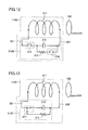
Referring to FIGS. 10 and 12 , secondary self-resonant coil 110B includes a capacitance modifier 312B, instead of capacitance modifier 312A, in the configuration of secondary self-resonant coil 110A.
Secondary self-resonant coil 110B further includes a discharging resistor 314 for setting capacitor 313 at a discharging state in a power non-reception mode.
Secondary self-resonant coil 110B further includes another relay 316 disconnecting discharging resistor 314 from capacitor 313 in a power reception mode, and connecting the discharging resistor from the capacitor in a power non-reception mode.
Discharging resistor 314 and another relay 316 are connected in series between the two electrodes of capacitor 313. Capacitor 313 is connected between a leading line 322 connected to the other end of coil body 311 and relay 315.
Referring to FIGS. 10 and 13 , secondary self-resonant coil 110C includes a capacitance modifier 312C, instead of capacitance modifier 312A, in the configuration of secondary self-resonant coil 110A.
Capacitance modifier 312C includes a leading line 321 connected to an end of the coil body, a relay 317 connected to leading line 321, and a capacitor 313 connected with coil body 311 via leading line 321 by relay 317 in a power reception mode, and disconnected from coil body 311 by the relay in a non-reception mode.
Secondary self-resonant coil 110C further includes a discharging resistor 314 for setting capacitor 313 at a discharging state in a power non-reception mode.
As described above, even if power was transmitted from the power feeding device, the region where power reception by resonance is effected can be eliminated from the vehicle in the present embodiment when power reception is not required.
Although each of the embodiments is described based on a series/parallel type hybrid vehicle in which the driving power of engine 176 is split by power split device 177 to be transmitted to driving wheel 178 and motor generator 172 as an electrical powered vehicle shown in FIG. 4 , the present invention is also applicable to other types of hybrid vehicles. For example, the present invention is applicable to the so-called series type hybrid vehicle using engine 176 only for driving motor generator 172, and the driving power of the vehicle is generated by motor generator 174 alone, a hybrid vehicle having only the regenerative energy among the kinetic energy generated by engine 176 collected as electric energy, a motor assistant type hybrid vehicle using the engine as the main motive power and assisted by the motor as necessary, and the like.
Further, the present invention is applicable to an electric vehicle that runs only by electric power, lacking an engine 176, or a fuel cell vehicle further including a fuel battery in addition to power storage device 150 as the DC power source. Moreover, the present invention is also applicable to an electrical powered vehicle 100 lacking a boost converter 162.
It should be understood that the embodiments disclosed herein are illustrative and non-restrictive in every respect. The scope of the present invention is defined by the terms of the claims, rather than the description of the embodiments set forth above, and is intended to include any modifications within the scope and meaning equivalent to the terms of the claims.
Claims (15)
1. A non-contact power reception device comprising:
a load to which electric power is fed, and
a receiving coil receiving electric power to be supplied to said load from an external transmission coil,
said receiving coil having a switching portion configured to switch between a first state and a second state, said first state being selected in a power reception mode in which said receiving coil is magnetically coupled with said transmission coil through resonance of a magnetic field, and said second state being selected in a power non-reception mode in which magnetic coupling of said receiving coil with said transmission coil through resonance is weaker than in said first state,
said receiving coil having an impedance differing between said first state and said second state,
said receiving coil including a coil body, said coil body being divided at a central region into a first portion and a second portion, and
said switching portion including an inductance modifier modifying an inductance of said coil body, said inductance modifier including a relay provided at the central region of said coil body, connecting and disconnecting said first portion and said second portion in a power reception mode and a power non-reception mode, respectively.
2. A non-contact power reception device comprising:
a load to which electric power is fed, and
a receiving coil receiving electric power to be supplied to said load from an external transmission coil,
said receiving coil having a switching portion configured to switch between a first state and a second state, said first state being selected in a power reception mode in which said receiving coil is magnetically coupled with said transmission coil through resonance of a magnetic field, and said second state being selected in a power non-reception mode in which magnetic coupling of said receiving coil with said transmission coil through resonance is weaker than in said first state,
said receiving coil including a coil body, and
said switching portion including a capacitance modifier modifying a capacitance of said coil body, said capacitance modifier including
a leading line connected to an end of said coil body,
a relay connected to said leading line, and
a capacitor connected to said coil body via said leading line by said relay in a power reception mode, and disconnected from said coil body by said relay in a power non-reception mode.
3. The non-contact power reception device according to claim 2 , further comprising
a discharging resistor for setting said capacitor at a discharging state in a power non-reception mode.
4. The non-contact power reception device according to claim 3 , further comprising
another relay disconnecting said discharging resistor from said capacitor in a power reception mode, and connecting said discharging resistor with said capacitor in a power non-reception mode.
5. The non-contact power reception device according to claim 3 , wherein
said relay disconnects said discharging resistor from said capacitor in a power reception mode, and connects said discharging resistor with said capacitor in a power non-reception mode.
6. The non-contact power reception device according to claim 1 , further comprising:
a voltage converter voltage-converting an input voltage for supply to said load, and
a rectifier rectifying AC voltage and providing the rectified voltage to said voltage converter as said input voltage,
wherein said receiving coil receives electric power from said transmission coil, and generates said AC voltage to be supplied to said rectifier.
7. The non-contact power reception device according to claim 1 , wherein
said non-contact power reception device is mounted on a vehicle, and receives electric power from said external transmission coil,
said non-contact power reception device further comprising a control unit performing control to switch said receiving coil between said first state and said second state,
wherein said control unit sets said receiving coil at said first state and at said second state when said vehicle meets and not meets a power reception condition, respectively.
8. The non-contact power reception device according to claim 7 , wherein
said vehicle includes a power storage device receiving charge electric power from said non-contact power reception device as said load,
said power reception condition includes the condition that a state of charge of said power storage device is less than a threshold value.
9. The non-contact power reception device according to claim 7 , wherein
said power reception condition includes the condition that a predetermined failure is not occurring at said vehicle.
10. A vehicle comprising the non-contact power reception device according to claim 1 .
11. The non-contact power reception device according to claim 2 , further comprising:
a voltage converter voltage-converting an input voltage for supply to said load, and
a rectifier rectifying AC voltage and providing the rectified voltage to said voltage converter as said input voltage,
wherein said receiving coil receives electric power from said transmission coil, and generates said AC voltage to be supplied to said rectifier.
12. The non-contact power reception device according to claim 2 , wherein
said non-contact power reception device is mounted on a vehicle, and receives electric power from said external transmission coil,
said non-contact power reception device further comprising a control unit performing control to switch said receiving coil between said first state and said second state,
wherein said control unit sets said receiving coil at said first state and at said second state when said vehicle meets and not meets a power reception condition, respectively.
13. The non-contact power reception device according to claim 12 , wherein
said vehicle includes a power storage device receiving charge electric power from said non-contact power reception device as said load,
said power reception condition includes the condition that a state of charge of said power storage device is less than a threshold value.
14. The non-contact power reception device according to claim 12 , wherein
said power reception condition includes the condition that a predetermined failure is not occurring at said vehicle.
15. A vehicle comprising the non-contact power reception device according to claim 2 .
Applications Claiming Priority (1)
| Application Number | Priority Date | Filing Date | Title |
|---|---|---|---|
| PCT/JP2008/068356 WO2010041318A1 (en) | 2008-10-09 | 2008-10-09 | Noncontact receiving device, and vehicle having the device |
Related Parent Applications (1)
| Application Number | Title | Priority Date | Filing Date |
|---|---|---|---|
| PCT/JP2008/068356 A-371-Of-International WO2010041318A1 (en) | 2008-10-09 | 2008-10-09 | Noncontact receiving device, and vehicle having the device |
Related Child Applications (1)
| Application Number | Title | Priority Date | Filing Date |
|---|---|---|---|
| US15/790,572 Division US11312248B2 (en) | 2008-10-09 | 2017-10-23 | Non-contact power reception device and vehicle including the same |
Publications (2)
| Publication Number | Publication Date |
|---|---|
| US20110181123A1 US20110181123A1 (en) | 2011-07-28 |
| US9827976B2 true US9827976B2 (en) | 2017-11-28 |
Family
ID=42100283
Family Applications (2)
| Application Number | Title | Priority Date | Filing Date |
|---|---|---|---|
| US13/122,625 Active 2030-03-12 US9827976B2 (en) | 2008-10-09 | 2008-10-09 | Non-contact power reception device and vehicle including the same |
| US15/790,572 Active 2030-08-20 US11312248B2 (en) | 2008-10-09 | 2017-10-23 | Non-contact power reception device and vehicle including the same |
Family Applications After (1)
| Application Number | Title | Priority Date | Filing Date |
|---|---|---|---|
| US15/790,572 Active 2030-08-20 US11312248B2 (en) | 2008-10-09 | 2017-10-23 | Non-contact power reception device and vehicle including the same |
Country Status (7)
| Country | Link |
|---|---|
| US (2) | US9827976B2 (en) |
| EP (2) | EP2346142B1 (en) |
| JP (1) | JP5287863B2 (en) |
| KR (1) | KR101171024B1 (en) |
| CN (1) | CN102177637B (en) |
| BR (1) | BRPI0823167B1 (en) |
| WO (1) | WO2010041318A1 (en) |
Cited By (2)
| Publication number | Priority date | Publication date | Assignee | Title |
|---|---|---|---|---|
| US10404107B2 (en) * | 2012-09-05 | 2019-09-03 | Renesas Electronics Corporation | Non-contact charging device, and non-contact power supply system using same |
| TWI738554B (en) * | 2020-11-02 | 2021-09-01 | 富達通科技股份有限公司 | Signal analysis circuit and method |
Families Citing this family (38)
| Publication number | Priority date | Publication date | Assignee | Title |
|---|---|---|---|---|
| US9473209B2 (en) * | 2008-08-20 | 2016-10-18 | Intel Corporation | Wireless power transfer apparatus and method thereof |
| US9515494B2 (en) * | 2008-09-27 | 2016-12-06 | Witricity Corporation | Wireless power system including impedance matching network |
| CN107026511A (en) * | 2008-09-27 | 2017-08-08 | 韦特里西提公司 | Wireless energy transfer systems |
| JP4478729B1 (en) * | 2008-12-24 | 2010-06-09 | 株式会社豊田自動織機 | Resonant non-contact charging device |
| JP2010193598A (en) * | 2009-02-17 | 2010-09-02 | Nippon Soken Inc | Noncontact power supply facility and noncontact power supply system |
| CA2801920A1 (en) | 2010-06-10 | 2011-12-15 | Access Business Group International Llc | Coil configurations for inductive power transfer |
| DE102010027640B4 (en) * | 2010-07-19 | 2023-10-05 | Sew-Eurodrive Gmbh & Co Kg | Electric charging system and method for contactless charging of a battery in a mobile unit |
| US9397726B2 (en) | 2010-08-23 | 2016-07-19 | Radeum, Inc. | System and method for communicating between near field communication devices within a target region using near field communication |
| KR101222749B1 (en) * | 2010-12-14 | 2013-01-16 | 삼성전기주식회사 | Wireless power transmission apparatus and transmission method thereof |
| JP5587165B2 (en) * | 2010-12-27 | 2014-09-10 | Necトーキン株式会社 | Non-contact power transmission system and power receiving antenna |
| EP2524834A1 (en) | 2011-05-18 | 2012-11-21 | Brusa Elektronik AG | Device for inductive charging of at least one electrical energy storage device of an electric car |
| US20120311363A1 (en) * | 2011-05-31 | 2012-12-06 | Nam Yun Kim | Wireless power transmission and charging system, and communication method of wireless power transmission and charging system |
| JP5703988B2 (en) * | 2011-06-17 | 2015-04-22 | トヨタ自動車株式会社 | Power receiving device, power transmitting device, vehicle, and non-contact power feeding system |
| WO2013042229A1 (en) * | 2011-09-21 | 2013-03-28 | トヨタ自動車株式会社 | Contactless power transmission device, contactless power receiving device and contactless power transceiver system |
| JP5807488B2 (en) * | 2011-09-28 | 2015-11-10 | ソニー株式会社 | Battery holder, battery storage case, battery pack, power storage system, electronic device, and electric vehicle |
| KR101875942B1 (en) | 2011-10-18 | 2018-07-06 | 엘지이노텍 주식회사 | Apparatus for receving wireless power and system for transmitting wireless power |
| US20140354041A1 (en) * | 2011-12-12 | 2014-12-04 | Toyota Jidosha Kabushiki Kaisha | Non-contact electric power transmission and reception system, vehicle, and electric power transmission device |
| TWI577104B (en) | 2012-01-06 | 2017-04-01 | 通路實業集團國際公司 | Wireless power receiver system and method of the same |
| US10187042B2 (en) | 2012-01-24 | 2019-01-22 | Philips Ip Ventures B.V. | Wireless power control system |
| JP5939853B2 (en) * | 2012-03-23 | 2016-06-22 | 日野自動車株式会社 | Contactless power supply |
| JP5885837B2 (en) * | 2012-05-21 | 2016-03-16 | 株式会社テクノバ | Contactless power transformer for moving objects |
| CN102963262B (en) * | 2012-11-30 | 2015-07-08 | 唐山轨道客车有限责任公司 | Power supply system for urban transportation vehicle |
| US20160001662A1 (en) * | 2013-02-25 | 2016-01-07 | Ut-Battelle, Llc | Buffering energy storage systems for reduced grid and vehicle battery stress for in-motion wireless power transfer systems |
| JP6361132B2 (en) * | 2013-12-24 | 2018-07-25 | トヨタ自動車株式会社 | Contactless power transfer system, charging station, and vehicle |
| GB2521676B (en) | 2013-12-31 | 2016-08-03 | Electric Road Ltd | System and method for powering an electric vehicle on a road |
| JP2016005327A (en) * | 2014-06-16 | 2016-01-12 | トヨタ自動車株式会社 | Non-contact power receiving device |
| US9889754B2 (en) | 2014-09-09 | 2018-02-13 | Qualcomm Incorporated | System and method for reducing leakage flux in wireless electric vehicle charging systems |
| US9923406B2 (en) | 2015-09-04 | 2018-03-20 | Qualcomm Incorporated | System and method for reducing leakage flux in wireless charging systems |
| CN104901439B (en) * | 2015-06-30 | 2017-08-08 | 京东方科技集团股份有限公司 | Magnetic resonance type wireless charging circuit |
| RU2691497C1 (en) * | 2016-05-25 | 2019-06-14 | Ниссан Мотор Ко., Лтд. | Device for noncontact power reception |
| DE102016211387A1 (en) * | 2016-06-24 | 2017-12-28 | Siemens Aktiengesellschaft | loader |
| CN106374629B (en) * | 2016-09-28 | 2019-03-05 | 中车唐山机车车辆有限公司 | Electromagnetic induction electric energy transmission system |
| DE102017202025A1 (en) * | 2017-02-09 | 2018-08-09 | Bayerische Motoren Werke Aktiengesellschaft | Method for checking a primary or secondary unit of an inductive charging system |
| JP6566580B2 (en) * | 2017-04-28 | 2019-08-28 | 株式会社Subaru | Sub-mobility charging system for vehicles |
| DE102017222879A1 (en) * | 2017-12-15 | 2019-06-19 | Volkswagen Aktiengesellschaft | Apparatus, method, and computer program for enabling a vehicle component, vehicle-to-vehicle communication module |
| DE112019003276A5 (en) * | 2018-06-29 | 2021-03-18 | Brusa Elektronik Ag | INDUCTIVE POWER TRANSFER WITH VIBRANT CIRCUIT AND METHOD FOR OPERATING THE DEVICE |
| JP2021197803A (en) * | 2020-06-12 | 2021-12-27 | キヤノン株式会社 | Rectifier circuit and wireless power transmission device |
| CN112910061B (en) * | 2021-04-07 | 2022-10-25 | 科世达(上海)机电有限公司 | Control method, device and medium for charging system load balancing |
Citations (48)
| Publication number | Priority date | Publication date | Assignee | Title |
|---|---|---|---|---|
| US3835389A (en) * | 1971-08-30 | 1974-09-10 | Mallory & Co Inc P R | Carrier current system |
| US3886377A (en) * | 1972-08-09 | 1975-05-27 | Mitsubishi Electric Corp | Control receiver |
| JPH08126120A (en) | 1994-10-19 | 1996-05-17 | Yazaki Corp | Automatic charging system of automobile |
| US5751115A (en) * | 1995-03-31 | 1998-05-12 | Philips Electronics North America Corporation | Lamp controller with lamp status detection and safety circuitry |
| KR19980024391U (en) | 1996-10-31 | 1998-07-25 | 양재신 | Automotive shift lever |
| US5898579A (en) * | 1992-05-10 | 1999-04-27 | Auckland Uniservices Limited | Non-contact power distribution system |
| US6124787A (en) * | 1997-01-15 | 2000-09-26 | Algonquin Scientific, Llc | Tire pressure sensing system |
| JP2001238372A (en) | 2000-02-24 | 2001-08-31 | Nippon Telegr & Teleph Corp <Ntt> | Power transmission system, electromagnetic field generator, and electromagnetic field receiver |
| JP2002078247A (en) | 2000-08-23 | 2002-03-15 | Nippon Telegr & Teleph Corp <Ntt> | Electromagnetic field receiving apparatus |
| US20020051435A1 (en) * | 2000-10-27 | 2002-05-02 | L-3 Communications Corporation | Two-dimensional channel bonding in a hybrid CDMA/FDMA fixed wireless access system to provide finely variable rate channels |
| US20020057075A1 (en) | 2000-09-04 | 2002-05-16 | Satoshi Takashige | Power feeding apparatus, transporter and transport system |
| US20020183003A1 (en) * | 2001-04-20 | 2002-12-05 | Mastek International | Wireless IC interconnection method and system |
| US20040102173A1 (en) * | 2002-11-25 | 2004-05-27 | Hooman Darabi | Bias filtering module including MOS capacitors |
| US20040198255A1 (en) * | 2002-03-22 | 2004-10-07 | Atsushi Hayashida | In-vehicle wireless device, management center, and operating-state notification system |
| CN1536735A (en) | 2003-04-09 | 2004-10-13 | ���ǵ�����ʽ���� | Robot charging system |
| US20050068019A1 (en) | 2003-09-30 | 2005-03-31 | Sharp Kabushiki Kaisha | Power supply system |
| US20050245207A1 (en) * | 2004-04-30 | 2005-11-03 | Kyocera Corporation | Wireless communication terminal and antenna switching control method |
| US20060131294A1 (en) | 2003-06-13 | 2006-06-22 | Duerr Systems Gmbh | Transport system |
| CN1802274A (en) | 2003-06-03 | 2006-07-12 | 丰田自动车株式会社 | Onboard battery control device and control method |
| CA2615123A1 (en) | 2005-07-12 | 2007-01-18 | Massachusetts Institute Of Technology | Wireless non-radiative energy transfer |
| US7183673B2 (en) * | 2003-02-04 | 2007-02-27 | Magneto-Inductive Systems Limited | Passive inductive switch |
| US20070109708A1 (en) | 2003-05-23 | 2007-05-17 | Auckland Uniservices Limited | Methods and apparatus for control of inductively coupled power transfer systems |
| US20070268018A1 (en) * | 2003-12-08 | 2007-11-22 | Koninklijke Philips Electronics Nv | Circuit Arrangement for Detuning a Resonant Circuit of an Mr Apparatus |
| US20080076351A1 (en) * | 2006-09-11 | 2008-03-27 | Takanori Washiro | Communication System, Communication Apparatus, and Electric-Field-Coupling Antenna |
| JP2008137451A (en) | 2006-11-30 | 2008-06-19 | Toyota Motor Corp | Automatic charging method and device of automated guided vehicle |
| US20080174267A1 (en) | 2007-01-17 | 2008-07-24 | Seiko Epson Corporation | Power transmission control device, power reception control device, non-contact power transmission system, power transmission device, power reception device and electronic instrument |
| CN101233666A (en) | 2005-07-30 | 2008-07-30 | Ls电线有限公司 | Rechargeable power supply, battery device, contact-less charger systems and method for charging rechargeable battery cell |
| US20080180332A1 (en) * | 2007-01-25 | 2008-07-31 | Junichi Noro | Antenna device |
| JP2008220130A (en) | 2007-03-07 | 2008-09-18 | Toyota Motor Corp | Power system for vehicle |
| CA2682284A1 (en) | 2007-03-27 | 2008-10-02 | Massachusetts Institute Of Technology | Wireless energy transfer |
| US20080265684A1 (en) * | 2006-10-25 | 2008-10-30 | Laszlo Farkas | High power wireless resonant energy transfer system |
| US20080278264A1 (en) | 2005-07-12 | 2008-11-13 | Aristeidis Karalis | Wireless energy transfer |
| US20090051224A1 (en) * | 2007-03-02 | 2009-02-26 | Nigelpower, Llc | Increasing the q factor of a resonator |
| US20090079270A1 (en) * | 2007-09-26 | 2009-03-26 | Seiko Epson Corporation | Structure having a power transmitting device |
| JP2009106136A (en) | 2007-10-25 | 2009-05-14 | Toyota Motor Corp | Electric vehicle and power feeding device for vehicle |
| US20090206675A1 (en) * | 2006-03-21 | 2009-08-20 | 'tmms Co., Ltd. | Device for transporting energy by partial influence through a dielectric medium |
| US20090230777A1 (en) * | 2008-03-13 | 2009-09-17 | Access Business Group International Llc | Inductive power supply system with multiple coil primary |
| US20090243394A1 (en) * | 2008-03-28 | 2009-10-01 | Nigelpower, Llc | Tuning and Gain Control in Electro-Magnetic power systems |
| WO2009140223A1 (en) | 2008-05-13 | 2009-11-19 | Qualcomm Incorporated | Reverse link signaling via receive antenna impedance modulation |
| US7656245B2 (en) * | 2004-03-22 | 2010-02-02 | Mobius Microsystems, Inc. | Integrated clock generator and timing/frequency reference |
| US20100065352A1 (en) * | 2008-09-18 | 2010-03-18 | Toyota Jidosha Kabushiki Kaisha | Noncontact electric power receiving device, noncontact electric power transmitting device, noncontact electric power feeding system, and electrically powered vehicle |
| US20100295506A1 (en) * | 2008-09-19 | 2010-11-25 | Toyota Jidosha Kabushiki Kaisha | Noncontact power receiving apparatus and vehicle including the same |
| US20110018494A1 (en) * | 2009-07-22 | 2011-01-27 | Sony Corporation | Power receiving apparatus, power transmission system, charging apparatus and power transmission method |
| US20110018358A1 (en) * | 2009-07-23 | 2011-01-27 | Sony Corporation | Contactless power supplying communication apparatus, contactless power receiving communication apparatus, power supplying communication controlling method and power receiving communication controlling method |
| US20110316349A1 (en) * | 2009-03-17 | 2011-12-29 | Sony Corporation | Electrical power transmission system and electrical power output device |
| US20120153894A1 (en) * | 2010-12-16 | 2012-06-21 | Qualcomm Incorporated | Wireless energy transfer and continuous radio station signal coexistence |
| US8552597B2 (en) * | 2006-03-31 | 2013-10-08 | Siemens Corporation | Passive RF energy harvesting scheme for wireless sensor |
| US20150333530A1 (en) * | 2014-05-19 | 2015-11-19 | Apple Inc. | Operating a Wireless Power Transfer System at Multiple Frequencies |
Family Cites Families (14)
| Publication number | Priority date | Publication date | Assignee | Title |
|---|---|---|---|---|
| US4800328A (en) * | 1986-07-18 | 1989-01-24 | Inductran Inc. | Inductive power coupling with constant voltage output |
| DE69313744T2 (en) * | 1992-06-10 | 1998-04-09 | Fuji Electric Co Ltd | AC drive device with variable speed and electric vehicle therefor |
| US5548200A (en) * | 1994-07-06 | 1996-08-20 | Norvik Traction Inc. | Universal charging station and method for charging electric vehicle batteries |
| SG54559A1 (en) | 1996-09-13 | 1998-11-16 | Hitachi Ltd | Power transmission system ic card and information communication system using ic card |
| JP3786392B2 (en) * | 1998-09-09 | 2006-06-14 | 本田技研工業株式会社 | Electric vehicle charging device |
| JP2002247781A (en) * | 2001-02-21 | 2002-08-30 | Yazaki Corp | Feeding device |
| US7614381B2 (en) * | 2003-03-28 | 2009-11-10 | Caterpillar Inc. | Power system with an integrated lubrication circuit |
| WO2006087944A1 (en) * | 2005-02-16 | 2006-08-24 | Toyota Jidosha Kabushiki Kaisha | Fuel device, vehicle, fuel filling device, and fuel filling system |
| JP4108695B2 (en) * | 2005-07-15 | 2008-06-25 | 三菱電機株式会社 | In-vehicle electronic control unit |
| JP4847891B2 (en) * | 2007-02-20 | 2011-12-28 | ソニー・エリクソン・モバイルコミュニケーションズ株式会社 | Portable electronic devices |
| JP5386348B2 (en) * | 2007-04-17 | 2014-01-15 | 株式会社エネルギー応用技術研究所 | Electric mobile body and quick charging method for electric mobile body |
| JP5152746B2 (en) * | 2007-08-08 | 2013-02-27 | 本田技研工業株式会社 | Fuel cell power supply |
| RU2430840C1 (en) * | 2007-08-24 | 2011-10-10 | Тойота Дзидося Кабусики Кайся | Transport facility |
| JP4604094B2 (en) * | 2008-01-23 | 2010-12-22 | トヨタ自動車株式会社 | Vehicle power supply device and vehicle window material |
-
2008
- 2008-10-09 JP JP2010532735A patent/JP5287863B2/en active Active
- 2008-10-09 EP EP08877266.0A patent/EP2346142B1/en active Active
- 2008-10-09 KR KR1020117010439A patent/KR101171024B1/en active IP Right Grant
- 2008-10-09 US US13/122,625 patent/US9827976B2/en active Active
- 2008-10-09 EP EP16189214.6A patent/EP3127742B1/en active Active
- 2008-10-09 BR BRPI0823167-2A patent/BRPI0823167B1/en active IP Right Grant
- 2008-10-09 CN CN2008801314530A patent/CN102177637B/en active Active
- 2008-10-09 WO PCT/JP2008/068356 patent/WO2010041318A1/en active Application Filing
-
2017
- 2017-10-23 US US15/790,572 patent/US11312248B2/en active Active
Patent Citations (104)
| Publication number | Priority date | Publication date | Assignee | Title |
|---|---|---|---|---|
| US3835389A (en) * | 1971-08-30 | 1974-09-10 | Mallory & Co Inc P R | Carrier current system |
| US3886377A (en) * | 1972-08-09 | 1975-05-27 | Mitsubishi Electric Corp | Control receiver |
| US5898579A (en) * | 1992-05-10 | 1999-04-27 | Auckland Uniservices Limited | Non-contact power distribution system |
| JPH08126120A (en) | 1994-10-19 | 1996-05-17 | Yazaki Corp | Automatic charging system of automobile |
| US5751115A (en) * | 1995-03-31 | 1998-05-12 | Philips Electronics North America Corporation | Lamp controller with lamp status detection and safety circuitry |
| KR19980024391U (en) | 1996-10-31 | 1998-07-25 | 양재신 | Automotive shift lever |
| US6124787A (en) * | 1997-01-15 | 2000-09-26 | Algonquin Scientific, Llc | Tire pressure sensing system |
| JP2001238372A (en) | 2000-02-24 | 2001-08-31 | Nippon Telegr & Teleph Corp <Ntt> | Power transmission system, electromagnetic field generator, and electromagnetic field receiver |
| JP2002078247A (en) | 2000-08-23 | 2002-03-15 | Nippon Telegr & Teleph Corp <Ntt> | Electromagnetic field receiving apparatus |
| US20020057075A1 (en) | 2000-09-04 | 2002-05-16 | Satoshi Takashige | Power feeding apparatus, transporter and transport system |
| US20020051435A1 (en) * | 2000-10-27 | 2002-05-02 | L-3 Communications Corporation | Two-dimensional channel bonding in a hybrid CDMA/FDMA fixed wireless access system to provide finely variable rate channels |
| US20020183003A1 (en) * | 2001-04-20 | 2002-12-05 | Mastek International | Wireless IC interconnection method and system |
| US20040198255A1 (en) * | 2002-03-22 | 2004-10-07 | Atsushi Hayashida | In-vehicle wireless device, management center, and operating-state notification system |
| US20040102173A1 (en) * | 2002-11-25 | 2004-05-27 | Hooman Darabi | Bias filtering module including MOS capacitors |
| US7183673B2 (en) * | 2003-02-04 | 2007-02-27 | Magneto-Inductive Systems Limited | Passive inductive switch |
| CN1536735A (en) | 2003-04-09 | 2004-10-13 | ���ǵ�����ʽ���� | Robot charging system |
| US20040201361A1 (en) | 2003-04-09 | 2004-10-14 | Samsung Electronics Co., Ltd. | Charging system for robot |
| US20070109708A1 (en) | 2003-05-23 | 2007-05-17 | Auckland Uniservices Limited | Methods and apparatus for control of inductively coupled power transfer systems |
| CN1802274A (en) | 2003-06-03 | 2006-07-12 | 丰田自动车株式会社 | Onboard battery control device and control method |
| US20060241826A1 (en) | 2003-06-03 | 2006-10-26 | Toyota Jidosha Kabushiki Kaisha | Onboard battery control device and control method |
| US20060131294A1 (en) | 2003-06-13 | 2006-06-22 | Duerr Systems Gmbh | Transport system |
| RU2006100189A (en) | 2003-06-13 | 2007-07-20 | Дюрр Системс Гмбх (De) | TRANSPORT SYSTEM |
| US20050068019A1 (en) | 2003-09-30 | 2005-03-31 | Sharp Kabushiki Kaisha | Power supply system |
| US20070268018A1 (en) * | 2003-12-08 | 2007-11-22 | Koninklijke Philips Electronics Nv | Circuit Arrangement for Detuning a Resonant Circuit of an Mr Apparatus |
| US7656245B2 (en) * | 2004-03-22 | 2010-02-02 | Mobius Microsystems, Inc. | Integrated clock generator and timing/frequency reference |
| US20050245207A1 (en) * | 2004-04-30 | 2005-11-03 | Kyocera Corporation | Wireless communication terminal and antenna switching control method |
| US20090267710A1 (en) | 2005-07-12 | 2009-10-29 | Joannopoulos John D | Wireless non-radiative energy transfer |
| US20100102639A1 (en) | 2005-07-12 | 2010-04-29 | Joannopoulos John D | Wireless non-radiative energy transfer |
| EP1902505A2 (en) | 2005-07-12 | 2008-03-26 | Massachusetts Institute of Technology (MIT) | Wireless non-radiative energy transfer |
| US20100264745A1 (en) | 2005-07-12 | 2010-10-21 | Aristeidis Karalis | Resonators for wireless power applications |
| KR20080031398A (en) | 2005-07-12 | 2008-04-08 | 메사추세츠 인스티튜트 오브 테크놀로지 | Wireless non-radiative energy transfer |
| CN101860089A (en) | 2005-07-12 | 2010-10-13 | 麻省理工学院 | Wireless non-radiative energy transfer |
| US20100253152A1 (en) | 2005-07-12 | 2010-10-07 | Aristeidis Karalis | Long range low frequency resonator |
| US20100237708A1 (en) | 2005-07-12 | 2010-09-23 | Aristeidis Karalis | Transmitters and receivers for wireless energy transfer |
| US20100237707A1 (en) | 2005-07-12 | 2010-09-23 | Aristeidis Karalis | Increasing the q factor of a resonator |
| CN101258658A (en) | 2005-07-12 | 2008-09-03 | 麻省理工学院 | Wireless non-radiative energy transfer |
| US20100237706A1 (en) | 2005-07-12 | 2010-09-23 | Aristeidis Karalis | Wireless power system and proximity effects |
| US20100231053A1 (en) | 2005-07-12 | 2010-09-16 | Aristeidis Karalis | Wireless power range increase using parasitic resonators |
| US20100225175A1 (en) | 2005-07-12 | 2010-09-09 | Aristeidis Karalis | Wireless power bridge |
| US20100207458A1 (en) | 2005-07-12 | 2010-08-19 | Joannopoulos John D | Wireless energy transfer over a distance with devices at variable distances |
| US20100201205A1 (en) | 2005-07-12 | 2010-08-12 | Aristeidis Karalis | Biological effects of magnetic power transfer |
| US20080278264A1 (en) | 2005-07-12 | 2008-11-13 | Aristeidis Karalis | Wireless energy transfer |
| JP2009501510A (en) | 2005-07-12 | 2009-01-15 | マサチューセッツ インスティテュート オブ テクノロジー | Wireless non-radiative energy transfer |
| US20100187911A1 (en) | 2005-07-12 | 2010-07-29 | Joannopoulos John D | Wireless energy transfer over distances to a moving device |
| US20100181844A1 (en) | 2005-07-12 | 2010-07-22 | Aristeidis Karalis | High efficiency and power transfer in wireless power magnetic resonators |
| US20100171370A1 (en) | 2005-07-12 | 2010-07-08 | Aristeidis Karalis | Maximizing power yield from wireless power magnetic resonators |
| US20090195332A1 (en) | 2005-07-12 | 2009-08-06 | John D Joannopoulos | Wireless non-radiative energy transfer |
| US20090195333A1 (en) | 2005-07-12 | 2009-08-06 | John D Joannopoulos | Wireless non-radiative energy transfer |
| US7741734B2 (en) | 2005-07-12 | 2010-06-22 | Massachusetts Institute Of Technology | Wireless non-radiative energy transfer |
| US20090224856A1 (en) | 2005-07-12 | 2009-09-10 | Aristeidis Karalis | Wireless energy transfer |
| US20100133919A1 (en) | 2005-07-12 | 2010-06-03 | Joannopoulos John D | Wireless energy transfer across variable distances with high-q capacitively-loaded conducting-wire loops |
| US20100133920A1 (en) | 2005-07-12 | 2010-06-03 | Joannopoulos John D | Wireless energy transfer across a distance to a moving device |
| US20090267709A1 (en) | 2005-07-12 | 2009-10-29 | Joannopoulos John D | Wireless non-radiative energy transfer |
| WO2007008646A2 (en) | 2005-07-12 | 2007-01-18 | Massachusetts Institute Of Technology | Wireless non-radiative energy transfer |
| US20100133918A1 (en) | 2005-07-12 | 2010-06-03 | Joannopoulos John D | Wireless energy transfer over variable distances between resonators of substantially similar resonant frequencies |
| US20100127573A1 (en) | 2005-07-12 | 2010-05-27 | Joannopoulos John D | Wireless energy transfer over a distance at high efficiency |
| US20100127574A1 (en) | 2005-07-12 | 2010-05-27 | Joannopoulos John D | Wireless energy transfer with high-q at high efficiency |
| US20100127575A1 (en) | 2005-07-12 | 2010-05-27 | Joannopoulos John D | Wireless energy transfer with high-q to more than one device |
| AU2010200044A1 (en) | 2005-07-12 | 2010-01-28 | Massachusetts Institute Of Technology | Wireless non-radiative energy transfer |
| CA2615123A1 (en) | 2005-07-12 | 2007-01-18 | Massachusetts Institute Of Technology | Wireless non-radiative energy transfer |
| US20100123355A1 (en) | 2005-07-12 | 2010-05-20 | Joannopoulos John D | Wireless energy transfer with high-q sub-wavelength resonators |
| US20100123354A1 (en) | 2005-07-12 | 2010-05-20 | Joannopoulos John D | Wireless energy transfer with high-q devices at variable distances |
| US20100123353A1 (en) | 2005-07-12 | 2010-05-20 | Joannopoulos John D | Wireless energy transfer with high-q from more than one source |
| US20100096934A1 (en) | 2005-07-12 | 2010-04-22 | Joannopoulos John D | Wireless energy transfer with high-q similar resonant frequency resonators |
| US20100102640A1 (en) | 2005-07-12 | 2010-04-29 | Joannopoulos John D | Wireless energy transfer to a moving device between high-q resonators |
| US20070222542A1 (en) | 2005-07-12 | 2007-09-27 | Joannopoulos John D | Wireless non-radiative energy transfer |
| US20100102641A1 (en) | 2005-07-12 | 2010-04-29 | Joannopoulos John D | Wireless energy transfer across variable distances |
| US20100117456A1 (en) | 2005-07-12 | 2010-05-13 | Aristeidis Karalis | Applications of wireless energy transfer using coupled antennas |
| US20100117455A1 (en) | 2005-07-12 | 2010-05-13 | Joannopoulos John D | Wireless energy transfer using coupled resonators |
| US20080211455A1 (en) | 2005-07-30 | 2008-09-04 | Dong-Young Park | Rechargeable Power Supply, Battery Device, Contactless Charger System And Method For Charging Rechargeable Battery Cell |
| CN101233666A (en) | 2005-07-30 | 2008-07-30 | Ls电线有限公司 | Rechargeable power supply, battery device, contact-less charger systems and method for charging rechargeable battery cell |
| US20090206675A1 (en) * | 2006-03-21 | 2009-08-20 | 'tmms Co., Ltd. | Device for transporting energy by partial influence through a dielectric medium |
| US8552597B2 (en) * | 2006-03-31 | 2013-10-08 | Siemens Corporation | Passive RF energy harvesting scheme for wireless sensor |
| US20080076351A1 (en) * | 2006-09-11 | 2008-03-27 | Takanori Washiro | Communication System, Communication Apparatus, and Electric-Field-Coupling Antenna |
| US20080265684A1 (en) * | 2006-10-25 | 2008-10-30 | Laszlo Farkas | High power wireless resonant energy transfer system |
| JP2008137451A (en) | 2006-11-30 | 2008-06-19 | Toyota Motor Corp | Automatic charging method and device of automated guided vehicle |
| US20080174267A1 (en) | 2007-01-17 | 2008-07-24 | Seiko Epson Corporation | Power transmission control device, power reception control device, non-contact power transmission system, power transmission device, power reception device and electronic instrument |
| US20080180332A1 (en) * | 2007-01-25 | 2008-07-31 | Junichi Noro | Antenna device |
| US20090051224A1 (en) * | 2007-03-02 | 2009-02-26 | Nigelpower, Llc | Increasing the q factor of a resonator |
| JP2008220130A (en) | 2007-03-07 | 2008-09-18 | Toyota Motor Corp | Power system for vehicle |
| EP2130287A1 (en) | 2007-03-27 | 2009-12-09 | Massachusetts Institute of Technology | Wireless energy transfer |
| CN101682216A (en) | 2007-03-27 | 2010-03-24 | 麻省理工学院 | Wireless energy transfer |
| WO2008118178A1 (en) | 2007-03-27 | 2008-10-02 | Massachusetts Institute Of Technology | Wireless energy transfer |
| CA2682284A1 (en) | 2007-03-27 | 2008-10-02 | Massachusetts Institute Of Technology | Wireless energy transfer |
| AU2007349874A2 (en) | 2007-03-27 | 2010-01-21 | Massachusetts Institute Of Technology | Wireless energy transfer |
| KR20100015954A (en) | 2007-03-27 | 2010-02-12 | 메사추세츠 인스티튜트 오브 테크놀로지 | Wireless energy transfer |
| US20090079270A1 (en) * | 2007-09-26 | 2009-03-26 | Seiko Epson Corporation | Structure having a power transmitting device |
| US20120032525A1 (en) | 2007-10-25 | 2012-02-09 | Toyota Jidosha Kabushiki Kaisha | Electrical Powered Vehicle and Power Feeding Device for Vehicle |
| US20100225271A1 (en) | 2007-10-25 | 2010-09-09 | Toyota Jidosha Kabushiki Kaisha | Electrical powered vehicle and power feeding device for vehicle |
| JP2009106136A (en) | 2007-10-25 | 2009-05-14 | Toyota Motor Corp | Electric vehicle and power feeding device for vehicle |
| US20110121778A1 (en) | 2007-10-25 | 2011-05-26 | Toyota Jidosha Kabushiki Kaisha | Electrical powered vehicle and power feeding device for vehicle |
| US20090230777A1 (en) * | 2008-03-13 | 2009-09-17 | Access Business Group International Llc | Inductive power supply system with multiple coil primary |
| US20090243394A1 (en) * | 2008-03-28 | 2009-10-01 | Nigelpower, Llc | Tuning and Gain Control in Electro-Magnetic power systems |
| KR20110010104A (en) | 2008-05-13 | 2011-01-31 | 퀄컴 인코포레이티드 | Reverse link signaling via receive antenna impedance modulation |
| WO2009140223A1 (en) | 2008-05-13 | 2009-11-19 | Qualcomm Incorporated | Reverse link signaling via receive antenna impedance modulation |
| US20090286476A1 (en) | 2008-05-13 | 2009-11-19 | Qualcomm Incorporated | Reverse link signaling via receive antenna impedance modulation |
| US9130407B2 (en) * | 2008-05-13 | 2015-09-08 | Qualcomm Incorporated | Signaling charging in wireless power environment |
| US20100065352A1 (en) * | 2008-09-18 | 2010-03-18 | Toyota Jidosha Kabushiki Kaisha | Noncontact electric power receiving device, noncontact electric power transmitting device, noncontact electric power feeding system, and electrically powered vehicle |
| US20100295506A1 (en) * | 2008-09-19 | 2010-11-25 | Toyota Jidosha Kabushiki Kaisha | Noncontact power receiving apparatus and vehicle including the same |
| US20110316349A1 (en) * | 2009-03-17 | 2011-12-29 | Sony Corporation | Electrical power transmission system and electrical power output device |
| US20110018494A1 (en) * | 2009-07-22 | 2011-01-27 | Sony Corporation | Power receiving apparatus, power transmission system, charging apparatus and power transmission method |
| US20110018358A1 (en) * | 2009-07-23 | 2011-01-27 | Sony Corporation | Contactless power supplying communication apparatus, contactless power receiving communication apparatus, power supplying communication controlling method and power receiving communication controlling method |
| US20120153894A1 (en) * | 2010-12-16 | 2012-06-21 | Qualcomm Incorporated | Wireless energy transfer and continuous radio station signal coexistence |
| US20150333530A1 (en) * | 2014-05-19 | 2015-11-19 | Apple Inc. | Operating a Wireless Power Transfer System at Multiple Frequencies |
Non-Patent Citations (4)
| Title |
|---|
| International Search Report issued in International Application No. PCT/JP2008/068356 dated Dec. 22, 2008 (with translation). |
| Jun. 28, 2012 Korean Office Action issued in Patent Application No. 10-2011-7010439 (with partial translation). |
| Kurs, A. et al., "Wireless Power Transfer via Strongly Coupled Magnetic Resonances," Science, Jul. 6, 2007, pp. 83-86, vol. 317. |
| Translation of Decision on Grant Patent for Invention dated Mar. 21, 2012 issued in Russian Patent Application No. 2011118343/07(027130). |
Cited By (3)
| Publication number | Priority date | Publication date | Assignee | Title |
|---|---|---|---|---|
| US10404107B2 (en) * | 2012-09-05 | 2019-09-03 | Renesas Electronics Corporation | Non-contact charging device, and non-contact power supply system using same |
| TWI738554B (en) * | 2020-11-02 | 2021-09-01 | 富達通科技股份有限公司 | Signal analysis circuit and method |
| US11733328B2 (en) | 2020-11-02 | 2023-08-22 | Fu Da Tong Technology Co., Ltd. | Signal analysis circuit and method |
Also Published As
| Publication number | Publication date |
|---|---|
| US20110181123A1 (en) | 2011-07-28 |
| CN102177637A (en) | 2011-09-07 |
| KR20110065569A (en) | 2011-06-15 |
| US20180043879A1 (en) | 2018-02-15 |
| US11312248B2 (en) | 2022-04-26 |
| EP2346142B1 (en) | 2017-01-11 |
| BRPI0823167B1 (en) | 2019-04-16 |
| WO2010041318A1 (en) | 2010-04-15 |
| BRPI0823167A2 (en) | 2015-06-23 |
| JPWO2010041318A1 (en) | 2012-03-01 |
| CN102177637B (en) | 2013-11-13 |
| EP2346142A4 (en) | 2013-02-13 |
| EP3127742B1 (en) | 2021-03-24 |
| EP3127742A1 (en) | 2017-02-08 |
| EP2346142A1 (en) | 2011-07-20 |
| KR101171024B1 (en) | 2012-08-08 |
| JP5287863B2 (en) | 2013-09-11 |
Similar Documents
| Publication | Publication Date | Title |
|---|---|---|
| US11312248B2 (en) | Non-contact power reception device and vehicle including the same | |
| US8421409B2 (en) | Noncontact power receiving apparatus for electrically-powered vehicle and vehicle including the same | |
| US9421868B2 (en) | Electrical powered vehicle and power feeding device for vehicle | |
| US8970060B2 (en) | Power feeding system and electrical powered vehicle | |
| US8646585B2 (en) | Non contact power transfer device and vehicle equipped therewith | |
| US20120098330A1 (en) | Coil unit, noncontact power receiving apparatus, noncontact power transmitting apparatus, noncontact power feeding system, and vehicle | |
| WO2010131346A1 (en) | Non-contact power reception device and vehicle equipped with same | |
| RU2461946C1 (en) | Device for non-contact power generation and transport means containing such device | |
| AU2015203204A1 (en) | Power supply system and electric vehicle |
Legal Events
| Date | Code | Title | Description |
|---|---|---|---|
| AS | Assignment |
Owner name: TOYOTA JIDOSHA KABUSHIKI KAISHA, JAPAN Free format text: ASSIGNMENT OF ASSIGNORS INTEREST;ASSIGNOR:ICHIKAWA, SHINJI;REEL/FRAME:026111/0001 Effective date: 20110323 |
|
| STCF | Information on status: patent grant |
Free format text: PATENTED CASE |
|
| MAFP | Maintenance fee payment |
Free format text: PAYMENT OF MAINTENANCE FEE, 4TH YEAR, LARGE ENTITY (ORIGINAL EVENT CODE: M1551); ENTITY STATUS OF PATENT OWNER: LARGE ENTITY Year of fee payment: 4 |