US9827062B2 - Secure equipment transfer system - Google Patents
Secure equipment transfer system Download PDFInfo
- Publication number
- US9827062B2 US9827062B2 US15/347,070 US201615347070A US9827062B2 US 9827062 B2 US9827062 B2 US 9827062B2 US 201615347070 A US201615347070 A US 201615347070A US 9827062 B2 US9827062 B2 US 9827062B2
- Authority
- US
- United States
- Prior art keywords
- docking
- brake
- arm
- transfer device
- various embodiments
- Prior art date
- Legal status (The legal status is an assumption and is not a legal conclusion. Google has not performed a legal analysis and makes no representation as to the accuracy of the status listed.)
- Active
Links
- 238000012546 transfer Methods 0.000 title claims abstract description 346
- 238000003032 molecular docking Methods 0.000 claims abstract description 388
- 230000007246 mechanism Effects 0.000 claims abstract description 124
- 238000000034 method Methods 0.000 claims description 35
- 125000006850 spacer group Chemical group 0.000 claims description 33
- 230000005405 multipole Effects 0.000 claims description 16
- 230000005484 gravity Effects 0.000 claims description 13
- 230000032258 transport Effects 0.000 description 39
- 239000000463 material Substances 0.000 description 28
- 230000008901 benefit Effects 0.000 description 14
- 230000003014 reinforcing effect Effects 0.000 description 12
- 239000003978 infusion fluid Substances 0.000 description 11
- 238000004519 manufacturing process Methods 0.000 description 11
- 230000006870 function Effects 0.000 description 10
- 230000000670 limiting effect Effects 0.000 description 10
- 239000004033 plastic Substances 0.000 description 10
- 229920003023 plastic Polymers 0.000 description 10
- 208000015181 infectious disease Diseases 0.000 description 9
- 230000004913 activation Effects 0.000 description 8
- 229910052782 aluminium Inorganic materials 0.000 description 8
- XAGFODPZIPBFFR-UHFFFAOYSA-N aluminium Chemical compound [Al] XAGFODPZIPBFFR-UHFFFAOYSA-N 0.000 description 8
- 229910052751 metal Inorganic materials 0.000 description 8
- 239000002184 metal Substances 0.000 description 8
- 238000005266 casting Methods 0.000 description 6
- 238000004140 cleaning Methods 0.000 description 6
- 238000003780 insertion Methods 0.000 description 6
- 230000037431 insertion Effects 0.000 description 6
- 230000014759 maintenance of location Effects 0.000 description 6
- 230000004048 modification Effects 0.000 description 6
- 238000012986 modification Methods 0.000 description 6
- 238000002360 preparation method Methods 0.000 description 6
- 238000013459 approach Methods 0.000 description 5
- 230000008569 process Effects 0.000 description 5
- 230000002829 reductive effect Effects 0.000 description 5
- 238000013461 design Methods 0.000 description 4
- 230000000694 effects Effects 0.000 description 4
- 238000012544 monitoring process Methods 0.000 description 4
- 238000012549 training Methods 0.000 description 4
- 208000028399 Critical Illness Diseases 0.000 description 3
- 239000000654 additive Substances 0.000 description 3
- 230000000996 additive effect Effects 0.000 description 3
- 239000002131 composite material Substances 0.000 description 3
- 230000006835 compression Effects 0.000 description 3
- 238000007906 compression Methods 0.000 description 3
- 230000008878 coupling Effects 0.000 description 3
- 238000010168 coupling process Methods 0.000 description 3
- 238000005859 coupling reaction Methods 0.000 description 3
- 238000003384 imaging method Methods 0.000 description 3
- 238000010348 incorporation Methods 0.000 description 3
- 238000001802 infusion Methods 0.000 description 3
- 238000012423 maintenance Methods 0.000 description 3
- 230000013011 mating Effects 0.000 description 3
- 150000002739 metals Chemical class 0.000 description 3
- 230000000474 nursing effect Effects 0.000 description 3
- 230000004044 response Effects 0.000 description 3
- 230000000717 retained effect Effects 0.000 description 3
- 238000000926 separation method Methods 0.000 description 3
- 229910001220 stainless steel Inorganic materials 0.000 description 3
- XLYOFNOQVPJJNP-UHFFFAOYSA-N water Substances O XLYOFNOQVPJJNP-UHFFFAOYSA-N 0.000 description 3
- DHKHKXVYLBGOIT-UHFFFAOYSA-N 1,1-Diethoxyethane Chemical compound CCOC(C)OCC DHKHKXVYLBGOIT-UHFFFAOYSA-N 0.000 description 2
- 241001161813 Aponogeton junceus Species 0.000 description 2
- 229920004943 Delrin® Polymers 0.000 description 2
- 235000015926 Proboscidea louisianica ssp. fragrans Nutrition 0.000 description 2
- 235000015925 Proboscidea louisianica subsp. louisianica Nutrition 0.000 description 2
- 229910000831 Steel Inorganic materials 0.000 description 2
- 238000005299 abrasion Methods 0.000 description 2
- 239000011354 acetal resin Substances 0.000 description 2
- 239000000853 adhesive Substances 0.000 description 2
- 230000001070 adhesive effect Effects 0.000 description 2
- 230000002411 adverse Effects 0.000 description 2
- 230000036626 alertness Effects 0.000 description 2
- -1 but not limited to Substances 0.000 description 2
- 238000011109 contamination Methods 0.000 description 2
- 238000013016 damping Methods 0.000 description 2
- 229920001971 elastomer Polymers 0.000 description 2
- 229920006351 engineering plastic Polymers 0.000 description 2
- 239000012530 fluid Substances 0.000 description 2
- 239000002783 friction material Substances 0.000 description 2
- 239000004519 grease Substances 0.000 description 2
- 229920001903 high density polyethylene Polymers 0.000 description 2
- 239000004700 high-density polyethylene Substances 0.000 description 2
- 238000000465 moulding Methods 0.000 description 2
- 239000002861 polymer material Substances 0.000 description 2
- 229920006324 polyoxymethylene Polymers 0.000 description 2
- 230000008707 rearrangement Effects 0.000 description 2
- 230000002441 reversible effect Effects 0.000 description 2
- 239000005060 rubber Substances 0.000 description 2
- 239000010935 stainless steel Substances 0.000 description 2
- 239000010959 steel Substances 0.000 description 2
- 238000002560 therapeutic procedure Methods 0.000 description 2
- 230000007704 transition Effects 0.000 description 2
- 238000010146 3D printing Methods 0.000 description 1
- 229910000838 Al alloy Inorganic materials 0.000 description 1
- 239000004743 Polypropylene Substances 0.000 description 1
- 229910000639 Spring steel Inorganic materials 0.000 description 1
- 230000006978 adaptation Effects 0.000 description 1
- 229910045601 alloy Inorganic materials 0.000 description 1
- 239000000956 alloy Substances 0.000 description 1
- 238000005452 bending Methods 0.000 description 1
- 230000008859 change Effects 0.000 description 1
- 238000007596 consolidation process Methods 0.000 description 1
- 238000010276 construction Methods 0.000 description 1
- 230000003247 decreasing effect Effects 0.000 description 1
- 238000000151 deposition Methods 0.000 description 1
- 238000010586 diagram Methods 0.000 description 1
- 238000005553 drilling Methods 0.000 description 1
- 230000003670 easy-to-clean Effects 0.000 description 1
- 230000003028 elevating effect Effects 0.000 description 1
- 230000008030 elimination Effects 0.000 description 1
- 238000003379 elimination reaction Methods 0.000 description 1
- 238000005516 engineering process Methods 0.000 description 1
- 238000000605 extraction Methods 0.000 description 1
- 231100001261 hazardous Toxicity 0.000 description 1
- 230000036541 health Effects 0.000 description 1
- 238000001746 injection moulding Methods 0.000 description 1
- 238000009434 installation Methods 0.000 description 1
- 238000005304 joining Methods 0.000 description 1
- 239000007788 liquid Substances 0.000 description 1
- 239000007769 metal material Substances 0.000 description 1
- 230000000399 orthopedic effect Effects 0.000 description 1
- 230000036961 partial effect Effects 0.000 description 1
- 229920000515 polycarbonate Polymers 0.000 description 1
- 239000004417 polycarbonate Substances 0.000 description 1
- 229920000379 polypropylene carbonate Polymers 0.000 description 1
- 229920001296 polysiloxane Polymers 0.000 description 1
- 238000003825 pressing Methods 0.000 description 1
- 230000000452 restraining effect Effects 0.000 description 1
- 238000009420 retrofitting Methods 0.000 description 1
- 238000010079 rubber tapping Methods 0.000 description 1
- 238000004904 shortening Methods 0.000 description 1
- 239000007779 soft material Substances 0.000 description 1
- 239000007787 solid Substances 0.000 description 1
- 238000001356 surgical procedure Methods 0.000 description 1
- 125000000391 vinyl group Chemical group [H]C([*])=C([H])[H] 0.000 description 1
- 229920002554 vinyl polymer Polymers 0.000 description 1
- 238000003466 welding Methods 0.000 description 1
Images


Classifications
-
- A—HUMAN NECESSITIES
- A61—MEDICAL OR VETERINARY SCIENCE; HYGIENE
- A61B—DIAGNOSIS; SURGERY; IDENTIFICATION
- A61B50/00—Containers, covers, furniture or holders specially adapted for surgical or diagnostic appliances or instruments, e.g. sterile covers
- A61B50/20—Holders specially adapted for surgical or diagnostic appliances or instruments
-
- A—HUMAN NECESSITIES
- A61—MEDICAL OR VETERINARY SCIENCE; HYGIENE
- A61G—TRANSPORT, PERSONAL CONVEYANCES, OR ACCOMMODATION SPECIALLY ADAPTED FOR PATIENTS OR DISABLED PERSONS; OPERATING TABLES OR CHAIRS; CHAIRS FOR DENTISTRY; FUNERAL DEVICES
- A61G12/00—Accommodation for nursing, e.g. in hospitals, not covered by groups A61G1/00 - A61G11/00, e.g. trolleys for transport of medicaments or food; Prescription lists
- A61G12/002—Supply appliances, e.g. columns for gas, fluid, electricity supply
- A61G12/005—Supply appliances, e.g. columns for gas, fluid, electricity supply mounted on the wall
-
- A—HUMAN NECESSITIES
- A61—MEDICAL OR VETERINARY SCIENCE; HYGIENE
- A61G—TRANSPORT, PERSONAL CONVEYANCES, OR ACCOMMODATION SPECIALLY ADAPTED FOR PATIENTS OR DISABLED PERSONS; OPERATING TABLES OR CHAIRS; CHAIRS FOR DENTISTRY; FUNERAL DEVICES
- A61G7/00—Beds specially adapted for nursing; Devices for lifting patients or disabled persons
- A61G7/002—Beds specially adapted for nursing; Devices for lifting patients or disabled persons having adjustable mattress frame
- A61G7/012—Beds specially adapted for nursing; Devices for lifting patients or disabled persons having adjustable mattress frame raising or lowering of the whole mattress frame
-
- A—HUMAN NECESSITIES
- A61—MEDICAL OR VETERINARY SCIENCE; HYGIENE
- A61G—TRANSPORT, PERSONAL CONVEYANCES, OR ACCOMMODATION SPECIALLY ADAPTED FOR PATIENTS OR DISABLED PERSONS; OPERATING TABLES OR CHAIRS; CHAIRS FOR DENTISTRY; FUNERAL DEVICES
- A61G7/00—Beds specially adapted for nursing; Devices for lifting patients or disabled persons
- A61G7/05—Parts, details or accessories of beds
- A61G7/0503—Holders, support devices for receptacles, e.g. for drainage or urine bags
-
- A—HUMAN NECESSITIES
- A61—MEDICAL OR VETERINARY SCIENCE; HYGIENE
- A61M—DEVICES FOR INTRODUCING MEDIA INTO, OR ONTO, THE BODY; DEVICES FOR TRANSDUCING BODY MEDIA OR FOR TAKING MEDIA FROM THE BODY; DEVICES FOR PRODUCING OR ENDING SLEEP OR STUPOR
- A61M5/00—Devices for bringing media into the body in a subcutaneous, intra-vascular or intramuscular way; Accessories therefor, e.g. filling or cleaning devices, arm-rests
- A61M5/14—Infusion devices, e.g. infusing by gravity; Blood infusion; Accessories therefor
- A61M5/1414—Hanging-up devices
- A61M5/1415—Stands, brackets or the like for supporting infusion accessories
-
- A—HUMAN NECESSITIES
- A61—MEDICAL OR VETERINARY SCIENCE; HYGIENE
- A61M—DEVICES FOR INTRODUCING MEDIA INTO, OR ONTO, THE BODY; DEVICES FOR TRANSDUCING BODY MEDIA OR FOR TAKING MEDIA FROM THE BODY; DEVICES FOR PRODUCING OR ENDING SLEEP OR STUPOR
- A61M5/00—Devices for bringing media into the body in a subcutaneous, intra-vascular or intramuscular way; Accessories therefor, e.g. filling or cleaning devices, arm-rests
- A61M5/14—Infusion devices, e.g. infusing by gravity; Blood infusion; Accessories therefor
- A61M5/1414—Hanging-up devices
- A61M5/1417—Holders or handles for hanging up infusion containers
-
- F—MECHANICAL ENGINEERING; LIGHTING; HEATING; WEAPONS; BLASTING
- F16—ENGINEERING ELEMENTS AND UNITS; GENERAL MEASURES FOR PRODUCING AND MAINTAINING EFFECTIVE FUNCTIONING OF MACHINES OR INSTALLATIONS; THERMAL INSULATION IN GENERAL
- F16B—DEVICES FOR FASTENING OR SECURING CONSTRUCTIONAL ELEMENTS OR MACHINE PARTS TOGETHER, e.g. NAILS, BOLTS, CIRCLIPS, CLAMPS, CLIPS OR WEDGES; JOINTS OR JOINTING
- F16B2/00—Friction-grip releasable fastenings
- F16B2/02—Clamps, i.e. with gripping action effected by positive means other than the inherent resistance to deformation of the material of the fastening
- F16B2/06—Clamps, i.e. with gripping action effected by positive means other than the inherent resistance to deformation of the material of the fastening external, i.e. with contracting action
- F16B2/10—Clamps, i.e. with gripping action effected by positive means other than the inherent resistance to deformation of the material of the fastening external, i.e. with contracting action using pivoting jaws
-
- F—MECHANICAL ENGINEERING; LIGHTING; HEATING; WEAPONS; BLASTING
- F16—ENGINEERING ELEMENTS AND UNITS; GENERAL MEASURES FOR PRODUCING AND MAINTAINING EFFECTIVE FUNCTIONING OF MACHINES OR INSTALLATIONS; THERMAL INSULATION IN GENERAL
- F16M—FRAMES, CASINGS OR BEDS OF ENGINES, MACHINES OR APPARATUS, NOT SPECIFIC TO ENGINES, MACHINES OR APPARATUS PROVIDED FOR ELSEWHERE; STANDS; SUPPORTS
- F16M11/00—Stands or trestles as supports for apparatus or articles placed thereon Stands for scientific apparatus such as gravitational force meters
- F16M11/20—Undercarriages with or without wheels
- F16M11/24—Undercarriages with or without wheels changeable in height or length of legs, also for transport only, e.g. by means of tubes screwed into each other
-
- F—MECHANICAL ENGINEERING; LIGHTING; HEATING; WEAPONS; BLASTING
- F16—ENGINEERING ELEMENTS AND UNITS; GENERAL MEASURES FOR PRODUCING AND MAINTAINING EFFECTIVE FUNCTIONING OF MACHINES OR INSTALLATIONS; THERMAL INSULATION IN GENERAL
- F16M—FRAMES, CASINGS OR BEDS OF ENGINES, MACHINES OR APPARATUS, NOT SPECIFIC TO ENGINES, MACHINES OR APPARATUS PROVIDED FOR ELSEWHERE; STANDS; SUPPORTS
- F16M11/00—Stands or trestles as supports for apparatus or articles placed thereon Stands for scientific apparatus such as gravitational force meters
- F16M11/42—Stands or trestles as supports for apparatus or articles placed thereon Stands for scientific apparatus such as gravitational force meters with arrangement for propelling the support stands on wheels
-
- F—MECHANICAL ENGINEERING; LIGHTING; HEATING; WEAPONS; BLASTING
- F16—ENGINEERING ELEMENTS AND UNITS; GENERAL MEASURES FOR PRODUCING AND MAINTAINING EFFECTIVE FUNCTIONING OF MACHINES OR INSTALLATIONS; THERMAL INSULATION IN GENERAL
- F16M—FRAMES, CASINGS OR BEDS OF ENGINES, MACHINES OR APPARATUS, NOT SPECIFIC TO ENGINES, MACHINES OR APPARATUS PROVIDED FOR ELSEWHERE; STANDS; SUPPORTS
- F16M13/00—Other supports for positioning apparatus or articles; Means for steadying hand-held apparatus or articles
- F16M13/02—Other supports for positioning apparatus or articles; Means for steadying hand-held apparatus or articles for supporting on, or attaching to, an object, e.g. tree, gate, window-frame, cycle
- F16M13/022—Other supports for positioning apparatus or articles; Means for steadying hand-held apparatus or articles for supporting on, or attaching to, an object, e.g. tree, gate, window-frame, cycle repositionable
-
- A—HUMAN NECESSITIES
- A61—MEDICAL OR VETERINARY SCIENCE; HYGIENE
- A61G—TRANSPORT, PERSONAL CONVEYANCES, OR ACCOMMODATION SPECIALLY ADAPTED FOR PATIENTS OR DISABLED PERSONS; OPERATING TABLES OR CHAIRS; CHAIRS FOR DENTISTRY; FUNERAL DEVICES
- A61G2203/00—General characteristics of devices
- A61G2203/70—General characteristics of devices with special adaptations, e.g. for safety or comfort
- A61G2203/80—General characteristics of devices with special adaptations, e.g. for safety or comfort for connecting a trolley to a device, e.g. bed or column table
-
- A—HUMAN NECESSITIES
- A61—MEDICAL OR VETERINARY SCIENCE; HYGIENE
- A61G—TRANSPORT, PERSONAL CONVEYANCES, OR ACCOMMODATION SPECIALLY ADAPTED FOR PATIENTS OR DISABLED PERSONS; OPERATING TABLES OR CHAIRS; CHAIRS FOR DENTISTRY; FUNERAL DEVICES
- A61G7/00—Beds specially adapted for nursing; Devices for lifting patients or disabled persons
- A61G7/0015—Beds specially adapted for nursing; Devices for lifting patients or disabled persons having means for attaching a cabinet in order to transport bed and cabinet together
-
- A—HUMAN NECESSITIES
- A61—MEDICAL OR VETERINARY SCIENCE; HYGIENE
- A61G—TRANSPORT, PERSONAL CONVEYANCES, OR ACCOMMODATION SPECIALLY ADAPTED FOR PATIENTS OR DISABLED PERSONS; OPERATING TABLES OR CHAIRS; CHAIRS FOR DENTISTRY; FUNERAL DEVICES
- A61G7/00—Beds specially adapted for nursing; Devices for lifting patients or disabled persons
- A61G7/05—Parts, details or accessories of beds
- A61G7/0506—Head or foot boards
-
- A—HUMAN NECESSITIES
- A61—MEDICAL OR VETERINARY SCIENCE; HYGIENE
- A61G—TRANSPORT, PERSONAL CONVEYANCES, OR ACCOMMODATION SPECIALLY ADAPTED FOR PATIENTS OR DISABLED PERSONS; OPERATING TABLES OR CHAIRS; CHAIRS FOR DENTISTRY; FUNERAL DEVICES
- A61G7/00—Beds specially adapted for nursing; Devices for lifting patients or disabled persons
- A61G7/10—Devices for lifting patients or disabled persons, e.g. special adaptations of hoists thereto
- A61G7/1025—Lateral movement of patients, e.g. horizontal transfer
-
- A—HUMAN NECESSITIES
- A61—MEDICAL OR VETERINARY SCIENCE; HYGIENE
- A61G—TRANSPORT, PERSONAL CONVEYANCES, OR ACCOMMODATION SPECIALLY ADAPTED FOR PATIENTS OR DISABLED PERSONS; OPERATING TABLES OR CHAIRS; CHAIRS FOR DENTISTRY; FUNERAL DEVICES
- A61G7/00—Beds specially adapted for nursing; Devices for lifting patients or disabled persons
- A61G7/10—Devices for lifting patients or disabled persons, e.g. special adaptations of hoists thereto
- A61G7/1073—Parts, details or accessories
-
- F—MECHANICAL ENGINEERING; LIGHTING; HEATING; WEAPONS; BLASTING
- F16—ENGINEERING ELEMENTS AND UNITS; GENERAL MEASURES FOR PRODUCING AND MAINTAINING EFFECTIVE FUNCTIONING OF MACHINES OR INSTALLATIONS; THERMAL INSULATION IN GENERAL
- F16M—FRAMES, CASINGS OR BEDS OF ENGINES, MACHINES OR APPARATUS, NOT SPECIFIC TO ENGINES, MACHINES OR APPARATUS PROVIDED FOR ELSEWHERE; STANDS; SUPPORTS
- F16M13/00—Other supports for positioning apparatus or articles; Means for steadying hand-held apparatus or articles
Abstract
A transfer device for a patient care apparatus includes: a first docking cup and a second docking cup, each of the first docking cup and the second docking cup aligned with a vertical axis, defining a conical surface aligned with the vertical axis, and sized to receive a receiver; a security mechanism enclosed within the transfer device; a support shaft disposed between the first docking cup and the second docking cup; and a shaft brake mechanism engageable with the support shaft, at least a portion of the shaft brake mechanism disposed below the support shaft and disposed between the first docking cup and the second docking cup.
Description
This application is a continuation of U.S. application Ser. No. 14/686,439, filed Apr. 14, 2015, which is a continuation-in-part of U.S. application Ser. No. 14/064,345, filed Oct. 28, 2013, which issued into U.S. Pat. No. 9,404,616 on Aug. 2, 2016, which is a continuation-in-part of U.S. patent application Ser. No. 13/104,531, filed May 10, 2011, which issued into U.S. Pat. No. 8,579,244 on Nov. 12, 2013, which claims the benefit of U.S. Provisional Application No. 61/332,918, filed May 10, 2010, each of which are hereby specifically incorporated by reference herein in their entireties.
The present invention relates generally to medical equipment transfer systems. More specifically, the present invention relates to a transfer system for reliably, safely and securely transferring life support apparatus between various support platforms when transporting critically ill patients.
In the daily care of critically ill patients, a great diversity of medical equipment, including infusion management equipment and supplies, pressure transducers, physiological monitors and other equipment is employed. Such equipment typically is set up at the patient's bedside where it is supported by various stands, racks or hangers. For example, the equipment may be supported by 5-star floor stands, attached to headwalls, suspended from booms that are affixed to the ceiling, floor or wall mounted columns, or on other stationary or mobile platforms.
The difficulty arises when, at times, these patients must be transported from their rooms for administering of various hospital services such as surgery, imaging, radiology or special procedures. Similarly, these patients may need to be transported to other specialized facilities. Such transports are often necessary under emergency conditions while patients are distressed and frail, requiring that such transports be competed rapidly and with minimal disruption of therapy, life support and monitoring.
In the known methods for moving patients in tandem with their support equipment, the caregivers in addition to moving the patient bed must also wheel several intravenous-fluid (IV) stands next to or behind a bed, or pile the equipment onto the mattress next to the patient. These techniques typically prove hazardous because the IV stands may fall and tear out patient connections. Such patient transports are also inefficient and costly because much staff time is required to prepare a patient for transport and many caregivers are needed for moving the equipment in tandem with the bed along corridors, into elevators and through doors.
In an attempt to overcome these shortcomings, several approaches for safer, more efficient and faster transport of patients and life support equipment have been provided in the prior art for the consolidation of life support equipment in a single equipment support structure, wherein the equipment support structure is moved from a support within the room to a mobile support platform such as a patient bed. One known method involves vertically lifting an equipment support structure out of a docking cradle of a headwall or other structure by utilizing the elevating mechanism of the hospital bed and, after transport, depositing the equipment support structure in a stationary docking cradle, again relying on the height adjustment mechanism of the bed.
U.S. Pat. No. 4,945,592 (Sims) teaches use of the hospital bed as a lifting mechanism but fails to provide a safety system to lock the support structure to either the mobile or stationary platform. Further the support equipment cannot be placed on the bed in an optimal position for patient care during transport. Also, conditions on the ground are such that it is difficult to align mobile and stationary platforms for seamless transfers. A further problem in this system is that the system components are not standardized and are therefore costly, and components generally do not conform to effective infection control requirements.
Similarly, U.S. Pat. No. 7,065,812 (Newkirk) also fails to provide a safety system to prevent accidental dislodging of the equipment support structure from engagement to stationary or mobile platforms. Arms and docking mechanisms are not standardized and therefore are costly to manufacture, and the support equipment cannot be moved into an optimal location for effective patient care during transport, nor do components generally conform to effective infection control requirements.
US Published Application No. 2006/0242763 (Graham) fails to provide a safety system to prevent accidental dislodging of the equipment support structure from engagement to stationary or mobile platforms. Additionally, the docking elements are arranged vertically above each other in co-axial relationship, which restricts optimal positioning during transport, fails to provide effective articulation between equipment support structure and patient bed, and therefore does not allow optimal in-transport equipment positioning.
U.S. Pat. Nos. 5,527,125 and 5,306,109 (Kreuzer) provide a safety system to prevent accidental dislodging of the equipment support structure from engagement to stationary or mobile platforms but positions the engagement cones in side-by-side, coplanar relationship which does not permit placement of support equipment vis-a-vis the patient for optimal care during transport. The approach is complex and costly as there is no standardization of crucial docking components, and the safety system relies on a complex and costly sliding mechanism.
U.S. Pat. No. 7,661,641 (Wong) teaches a safety system to prevent accidental dislodging of the equipment support structure from engagement to stationary or mobile platforms but also arranges the docking elements vertically above each other in co-axial relationship which restricts optimal positioning during transport, fails to provide effective articulation between equipment support structure and patient bed and therefore does not allow optimal in-transport equipment positioning. The safety system and the requirement for a mobile base make this approach complex and costly to implement.
Other approaches as disclosed in U.S. Pat. Nos. 7,314,200 and 4,511,158 utilize transfer and docking by connecting to mobile and stationary platforms using a horizontal docking movement rather than a vertical one. These approaches are overly sensitive to misalignment in height and axial orientation of the components to be docked.
In view of the shortcomings of known medical equipment transfer systems, the present invention provides a novel transfer apparatus for transferring said life support equipment between different platforms such as a stationary wall or ceiling support structure and a mobile support platform such as a patient bed. There is therefore a need for a system for transferring patient support equipment from stationary to mobile platforms that is of low mechanical complexity, and that utilizes fewer, standardized, simpler components to permit low-cost manufacturing and reduced service and warranty costs by minimizing field maintenance and extending the mean time between failures. There is also a need for a patient transfer and transport system that assures the life support equipment is securely locked to either the stationary or mobile platform so that it cannot be accidentally removed or dislodged, yet allows seamless transfer of the life support equipment between stationary and mobile platforms that automatically engages the security lock during transfer by utilizing a vertical lift mechanism such as a typical, motorized patient bed. There is a further need for a patient transfer and transport system that minimizes in-service training of caregivers, by making transfer from stationary to mobile platforms intuitive, minimizing training of transport staff by eliminating or automating critical steps in the procedure, and relying less on memory or alertness of personnel. There is still a further need for a patient transfer and transport system that minimizes crevices, exposed fasteners and upward-facing cavities to facilitate effective cleaning and infection control. There is yet a further need for a patient transfer and transport system that is relatively insensitive to the misalignment of equipment typically encountered in hospitals during transfers between stationary and mobile platforms. There is also a need for a patient transfer and transport system that permits nursing staff to position and re-position the support equipment relative to the patient that allows ready access to the patient and facilitates easy monitoring and control of life-support equipment during transport, minimizes the total footprint of the bed and associated equipment, and minimizes the risk of dislodging fluid lines, cables and leads between equipment and patient during transfer between stationary and mobile platforms. Finally, there is a need for a patient transfer and transport system that is articulated to allow caregivers full freedom in repositioning the patient support equipment around the patient's head and allows the articulations to be locked in place during transport.
In this regard, the present invention provides an equipment transfer device that is transferrable from one support to another support. The transport device is comprised of a clamshell housing having two substantially identical but mirrored outer shells that are held together by screws. Each housing half further comprises two similar, half-conical recesses, preferably disposed on generally parallel, spaced-apart vertical axes such that, when assembled to form said clam-shell, the two housing halves form circular docking cups that are open to the bottom.
The docking cups are spaced apart horizontally along the central plane of the clamshell housing such that each docking cup can receive a docking cone from below, as further described below. Each docking cone is supported on a structure and is capable of moving in a generally vertical direction into engagement or out of engagement along the axis of their respective docking cups while maintaining horizontal separation to avoid interference and collision with one another. The docking cups may be positioned symmetrically on a horizontal plane, but in alternate embodiments the docking cups are preferably disposed on different horizontal levels, with a vertical separation between the upper and lower docking cups.
Additionally, a support post is rigidly trapped and fastened between the two housing halves, preferably in coaxial relationship with the upper docking cup. The support post protrudes from the upper end of the transfer device as a base to which an equipment support structure is rotatably attached. Support structures of various configurations may be interchangeably attached according to specific caregiver requirements.
In accordance with another aspect of the preferred embodiment of the present invention, there is provided a security mechanism that secures a first docking cone, upon engagement to the transfer device, to a first docking cup. The security mechanism only releases the first docking cone from the first docking cup upon insertion and full engagement of a second docking cone in the second docking cup. The security mechanism of this invention prevents accidental disengagement of the transfer device from either the stationary or mobile platforms to which it is docked as it securely locks an engaged docking cone to its respective docking cup. The transfer device may only be disengaged from a first docking cone when another docking cone is fully inserted and engaged in the other docking cup, or vice-versa. The security mechanism operates autonomously without human intervention. It is activated by user control of the vertical movement of the docking activation mechanism, such as the height adjustment of a hospital bed.
It is therefore an object of the present invention to provide a system for transferring patient support equipment from stationary to mobile platforms that is of low mechanical complexity, and that utilizes fewer, standardized, simpler components to permit low-cost manufacturing and reduced service and warranty costs by minimizing field maintenance and extending the mean time between failures. It is a further object of the present invention to provide a patient transfer and transport system that assures the life support equipment is securely locked to either the stationary or mobile platform so that it cannot be accidentally removed or dislodged, yet allows seamless transfer of the life support equipment between stationary and mobile platforms that automatically engages the security lock during transfer by utilizing a vertical lift mechanism such as a typical, motorized patient bed. It is still a further object of the present invention to provide a patient transfer and transport system that minimizes in-service training of caregivers, by making transfer from stationary to mobile platforms intuitive, minimizing training of transport staff by eliminating or automating critical steps in the procedure, and relying less on memory or alertness of personnel. It is yet a further object of the present invention to provide a patient transfer and transport system that minimizes crevices, exposed fasteners and upward-facing cavities to facilitate effective cleaning and infection control. It is a further object of the present invention to provide a patient transfer and transport system that is relatively insensitive to the misalignment of equipment typically encountered in hospitals during transfers between stationary and mobile platforms. It is still a further object of the present invention to provide a patient transfer and transport system that permits nursing staff to position and re-position the support equipment relative to the patient that allows ready access to the patient and facilitates easy monitoring and control of life-support equipment during transport, minimizes the total footprint of the bed and associated equipment, and minimizes the risk of dislodging fluid lines, cables and leads between equipment and patient during transfer between stationary and mobile platforms. Finally, it is an object of the present invention to provide a patient transfer and transport system that is articulated to allow caregivers full freedom in repositioning the patient support equipment around the patient's head and allows the articulations to be locked in place during transport.
Also disclosed is a transfer device for a patient care apparatus comprising: a first docking cup and a second docking cup, each of the first docking cup and the second docking cup aligned with a vertical axis, defining a conical surface aligned with the vertical axis, and sized to receive a receiver; a security mechanism enclosed within the transfer device; a support shaft disposed between the first docking cup and the second docking cup; and a shaft brake mechanism engageable with the support shaft, at least a portion of the shaft brake mechanism disposed below the support shaft and disposed between the first docking cup and the second docking cup.
Also disclosed is a transfer device for a patient care apparatus comprising: a first docking cup and a second docking cup, each of the first docking cup and the second docking cup aligned with a vertical axis, defining a conical surface aligned with the vertical axis, defining an opening facing downward, and sized to receive a receiver; and a security mechanism enclosed within the transfer device.
Also disclosed is a transfer system for a patient care apparatus comprising: a receiver arm; and an arm brake mechanism, the arm brake mechanism comprising a brake shaft, a brake spacer, and an arm brake fastener, the brake spacer coupled to the brake shaft and configured to rotate together with the brake shaft.
Also disclosed is a method of using a transfer system, the method comprising: engaging a receiver of the transfer system with a transfer device of the transfer system, the transfer device comprising a first docking cup, a second docking cup, a support shaft, and a shaft brake mechanism engageable with the support shaft, the support shaft disposed between the first docking cup and the second docking cup and at least a portion of the shaft brake mechanism disposed below the support shaft and disposed between the first docking cup and the second docking cup; disengaging the shaft brake mechanism by hand; rotating the support shaft; and re-engaging the shaft brake mechanism by hand.
These together with other objects of the invention, along with various features of novelty that characterize the invention, are pointed out with particularity in the further description annexed hereto and forming a part of this disclosure. For a better understanding of the invention, its operating advantages and the specific objects attained by its uses, reference should be had to the accompanying drawings and descriptive matter in which there is illustrated a preferred embodiment of the invention.
Various implementations described in the present disclosure may include additional systems, methods, features, and advantages, which may not necessarily be expressly disclosed herein but will be apparent to one of ordinary skill in the art upon examination of the following detailed description and accompanying drawings. It is intended that all such systems, methods, features, and advantages be included within the present disclosure and protected by the accompanying claims.
The features and components of the following figures are illustrated to emphasize the general principles of the present disclosure. Corresponding features and components throughout the figures may be designated by matching reference characters for the sake of consistency and clarity. In the drawings which illustrate the best mode presently contemplated for carrying out the present invention:
Disclosed is a transfer system and associated methods, systems, devices, and various apparatuses. The transfer system includes a transfer device, one or more receivers, and arms in various embodiments. It would be understood by one of skill in the art that the disclosed transfer system and transfer device are described in but a few exemplary embodiments among many. No particular terminology or description should be considered limiting on the disclosure or the scope of any claims issuing therefrom.
Now referring to the drawings, the equipment transfer system is shown and generally illustrated in the figures. As can be seen the principal component of the transfer system is a transfer device 20 that can be selectively supported and moved between a stationary support platform 300 and a mobile support platform 400 to facilitate the transfer of patient care apparatus 200 supported thereon.
Turning to FIG. 1 , the transfer system 10 includes a stationary support platform 300, a mobile support platform 400 and a transfer device 20 that supports a patient care apparatus 200 and is capable of transferring the patient care apparatus 200 between a stationary support platform 300 and a mobile support platform 400 and vice-a-versa. Within the scope of the present invention the term “transfer” refers to transferring patient support equipment between stationary support platforms including walls, headwalls, ceiling-mounted or wall-mounted booms from various manufacturers, free-standing and/or movable columns and other structures typically found in hospital rooms and treatment facilities to which a stationary cone arm connector 301 may be attached, and mobile support platforms such as patient beds, gurneys, wheelchairs, ambulances, helicopters or other mobile platforms, and vice-versa. As anyone familiar with the art will appreciate, substituting alternative rotatable attachment means, alternative stationary support platforms, alternatives to post 308 and/or stationary cone arm connectors 301, as well as transfers between stationary platforms or between mobile platforms, are within the scope of this invention.
Referring to stationary support platform 300 and mobile support platform 400 of the preferred embodiment, as shown in FIGS. 1-3 , platforms 300 and 400 may both support a cone arm 150. Cone arm 150 has a distal end 174 and a proximal end 173. The distal end 174 comprises docking cone 100 for docking with transfer device 20 and the proximal end 173 comprises arm joint 151 which may be attached to stationary or mobile support platforms 300 or 400, respectively. Cone arm 150 may be attached to a stationary support platform, such as post 308, or directly to a wall 465 using stationary cone arm connector 301. Cone arm 150 may also be attached to a mobile support platform 400, such as a hospital bed, as more fully described below, using mobile cone arm adapter 413 which is mated to accessory bracket 406 of a hospital bed 410 by means of bed post 412 or other known connection.
As shown in FIGS. 4 & 9 , when treated in a hospital room, a patient typically may be attached to patient care apparatus 201 connected to an equipment support structure 200. The equipment support structure preferably is attached to transfer device 20 and rotatably docked to docking cone 100 of a cone arm 150 that is rotatably joined to a stationary cone arm connector 301. Cone arm 150, docking cone 100 and cone arm connector 301 provide articulation so that stationary support platform 300 may be positioned for optimal patient care. Having patient care apparatus 201 physically detached from hospital bed 410, while a patient is in a room, is preferred in many health care facilities in order to provide unobstructed patient access all around hospital bed 410. As used herein, the term “docking” and “docking maneuver” refers to inserting a docking cone into a docking cup generally in coaxial alignment and in a load-bearing relationship where cone arm 150 supports transfer device 20 and patient care apparatus 201.
As shown in FIGS. 2 and 3 , the cone arms 150 that are attached to both the stationary support platform 300 and the mobile support platform 400 are substantially identical. In the preferred embodiment, arm length 175 is approximately 9.5 inches. However, arm length 175 may reasonably range between 4 inches and 15 inches, although shorter and longer arm lengths 175 may be used to meet specific requirements, and cone arms 150 of different lengths may be employed in a single transfer system 10. In addition, in the preferred embodiment shown in FIGS. 14 & 16 , arm joint 151 and docking cone 40, as well as the components required in the arm joint 151 for achieving joint stability and user adjustment, have both been standardized in order to minimize manufacturing cost and parts inventory. As anyone familiar with the art may recognize, one or more additional articulating arm segments may be installed between arm joint 151 and stationary arm connector 301, and/or between mobile cone arm adapter and arm joint 151, in order to extend the reach and flexibility of system 10.
As shown in FIGS. 10-13 , stationary arm connector 307 and mobile cone arm adapter 413 have a stationary contact interface 312 and a mobile contact interface 411, respectively. Both contact interfaces 312, 411 are substantially identical and enable essentially identical attachment to arm joint 151 located at the proximal end 173 of cone arm 150, regardless whether attached to mobile or stationary platforms. As shown in FIGS. 14 & 15 , standardization of attachment and joint tensioning components of cone arms 150 is instrumental in reducing the complexity and manufacturing cost of transfer system 10. Stationary contact interface 313 is a flat surface 312 and is perpendicular to the longitudinal axis of bolt 302. Bolt 302 protrudes from stationary contact interface 312 and is held in place and secured against rotation by capturing hexagonal bolt head 305 with bolt head restraints 310. Analogously, the mobile contact interface is perpendicular to longitudinal axis of bolt 302. Bolt 302 protrudes from mobile contact interface 411 and is held in place and secured against rotation by capturing hexagonal bolt head 305 with bolt head restraints 310.
As shown in FIGS. 2, 9 & 10 , stationary cone arm connector 301 is comprised of arm connector 307 and clamp 306. Arm connector 307 and clamp 306 cooperate, in a clamping and load-bearing relationship, to firmly attach stationary cone arm connector 301 to post 308 by means of attachment screws 318.
In order to achieve low manufacturing cost, the number of parts and components required in transfer system 10 is minimized by standardization. Cone arm 150 used with a stationary support platform 300 is preferably substantially identical to cone arm 150 used with a mobile support platform 400, and the components required and method used for attaching cone arm 150 to arm connector 307 of stationary support platform 300, as shown in FIG. 2 , is preferably substantially identical to the components required and method used for attaching cone arm 150 to mobile cone arm adapter 413 of mobile support platform 400, as shown in FIG. 3 .
As shown in FIGS. 2, 11 & 12 , arm joint 151 may be attached to stationary arm connector 307 to form a rotatable joint that permits cone arm 150 to rotate on arm connector axis 461 a in a horizontal plane. The threaded bolt end 313 of bolt 302 is pushed up through bolt hole 315 with the bolt head base 316 of hexagonal head 305 in contact with bolt head bearing surface 303 and hexagonal head 305 in engagement with bolt restraints 310 to prevent rotation of bolt 302. Threaded bolt end 313 may issue from the center of, and perpendicularly to, stationary contact interface 312. Thrust bearing 157 may be placed on stationary contact interface 312 in coaxial relationship with bolt 302 and with lower bearing face 182 in coplanar and sliding relationship with stationary contact interface 312 to constitute a standardized attachment for cone arms 150 to stationary support platforms 300.
As shown in FIGS. 11-15 , the connections between cone arm 150 and arm connector 307, and cone arm 150 and mobile cone arm connector 413, are substantially identical. Cone arm 150 may be placed onto bolt 302 with bolt bore 177 in coaxial relationship, and with the upper bearing face 183 of thrust bearing 157 in coplanar and sliding relationship with bearing surface 152 of arm joint 151, and with threaded bolt end 313 extending coaxially up through recess 153 of arm joint 151. Lock thrust bearing 158 may be placed over threaded bolt end 313 with the lower bearing face 182 of lock thrust bearing 158 in coplanar and sliding relationship with inner joint pressure surface 156. Pressure plate 159 may be threaded onto the threaded bolt end 313 by means of tapped center hole 162, with pressure surface 160 in coplanar relationship with, and tightened against, the upper bearing face 183 of lock thrust bearing 158 in order to cause tension on bolt 302 and take up slack in arm joint 151. Jam nut 169 is threaded onto threaded bolt end 313 and tightened against pressure plate 159 in jam-nut relationship to secure pressure plate 159 against rotation relative to bolt 302 during continued use of transfer system 10.
As shown in FIGS. 14 & 15 , adjustment knob 190 is in threaded engagement with threaded bolt end 313 of bolt 302 that protrudes through jam nut 169. Clockwise or counter-clockwise rotation, respectively, of adjustment knob 190, permits users to adjust the friction between cone arms 150 and stationary and mobile support platforms 300 and 400, respectively, without affecting the load bearing ability or stability of arm joint 151. Adjustment knob 190 has a threaded center boss 191 with tapered outer surface 192, crown 194 and side skirt 193. Side skirt 193 is sized to protrude over, and overlap with, recess rim 154 of cone arm 150 when adjustment knob 190 is fully tightened to facilitate infection control. To offer better hand purchase when users tighten and loosen adjustment knob 190, crown 194 and side skirt 193 may be grooved to retain an external O-ring 195 or may be indented, serrated or otherwise shaped (not shown). Tapered outer surface 192 of threaded center boss 191 cooperates with friction wedge 163 to control joint friction.
Tightening adjustment knob 190 on bolt 302 pushes friction wedge 163 against pressure plate 159 and forces tapered outer surface 192 of threaded center boss 191 of adjustment knob 190 against inner wedge taper 166 of friction wedge 163 causing friction wedge 163 to expand. Outer wedge taper 165 of friction wedge 163 is forced against inner wall 155 of recess 153 of arm joint 151 to progressively increase or decrease joint friction when a user tightens or loosens adjustment knob 190.
Analogously, cone arm 150 may be attached to mobile support platform 300 by means of mobile cone arm adapter 413 fastened to vertical bed post 412. There are many known mobile support platforms 400, including hospital beds, stretchers and gurneys from various manufacturers, special procedure support devices, wheelchairs, and other structures typically found in hospitals and treatment facilities to which a mobile cone arm adapter 413 may be adapted for attachment to alternative stationary and mobile support platforms 300, 400 to enable system 10 to be used with known variations in known attachment methods. Such adaptations, as anyone familiar with the art may recognize, are within the scope of this invention. Analogously, as shown in FIGS. 3, 13 & 14 , arm joint 151 may also be attached to mobile cone arm adapter 413 to form a rotatable joint that permits cone arm 150 to rotate on bed post axis 461 b in a horizontal plane. Threaded bolt end 313 of bolt 302 is pushed up through bolt hole 315 with the bolt head base 316 of hexagonal head 305 in contact with bolt head bearing surface 303 and hexagonal sides of bolt head 305 in engagement with bolt restraints 310 to prevent rotation of bolt 302. Threaded bolt end 313 may issue from in the center of, and perpendicularly to, mobile contact interface 411. A thrust bearing 157 may be placed on mobile contact interface 411 in coaxial relationship with bolt 302 and with lower bearing face 182 of thrust bearing 157 in coplanar and sliding relationship with mobile contact interface 411 to constitute a standardized attachment for cone arms 150 to mobile support platforms 400.
As shown in FIGS. 1 & 2-9 , transfer device 20 is selectively attachable to the docking cones 100 of cone arms 150 in order to transfer patient care apparatus 201 between stationary support platforms 300 and mobile support platforms 400. The transfer device 20 supports equipment support structure 200 by means of support post 41 that is rigidly attached to, and protrudes out of, upper end 33 of clamshell housing 21 and rotatably engages equipment support structure 200. Hospital staff may attach patient care apparatus 201 to equipment support structure 200, such as infusion management devices and supplies, monitoring equipment, and other life support apparatus that may be required for the care of critically ill patients. The vertical axis of rotation (not shown) of equipment support structure 250 preferably is coaxial with upper docking cone axis 462.
The configuration of equipment support structure 200 may vary depending on type and number of patient care apparatus being used, hospital protocols, type of therapy or life support requirements. However, various configurations of equipment support structures 200 preferably share the capability of being interchangeably attached to support post 41. Generally, transfer device 20 and equipment support structure 200 are rotatably joined and paired for the duration of a patient's hospital stay or longer.
The method of preparing a patient for transport, safely transferring patient care apparatus 201 from attachment in the room to attachment to bed 410, safely transporting a patient to another location, and safely and expeditiously returning the patient to a room, as shown in FIGS. 1-5, 11 & 14 , is described below. As used in this disclosure, the term “transport” refers to moving a patient in tandem with life support equipment attached to a mobile platform such as a patient bed, gurney, wheelchair, ambulance, helicopter or other mobile platform between locations within or between medical facilities, such as intensive care rooms, operating rooms, radiology and other imaging facilities, catheterization labs, or between buildings and hospitals.
Before transporting a patient from a room to another location, as shown in FIG. 4 , upper docking cup 74 of transfer device 20 typically will be docked with, and secured to, a stationary support structure 300. In preparation of patient transport, transfer device 20 may be repositioned so that the lower docking cup faces hospital bed 410, and hospital bed 410 preferably may be moved closer to the stationary support platform 300. Activation of lift mechanism 403 may lower mattress height 450 from working height 451 to low docking level 452 to permit docking cone 100 of mobile support platform 400 to be maneuvered directly underneath, and into generally coaxial alignment with, lower docking cup 75 of transfer device 20. Activation of lift mechanism 403 of hospital bed 410 may raise mattress 402 and also raise docking cone 100 of mobile support platform 400, causing it to dock with transfer device 20. As shown in FIG. 5 , docking cone 100 attached to stationary support platform 300 and docking cone 100 attached to mobile support platform 400 are simultaneously engaged in their respective docking cups 74, 75. Under continued activation of lift mechanism 403, security mechanism 120 automatically releases transfer device 20 from the stationary docking cone 100 and locks transfer device 20 to the mobile docking cone 100, as more fully described below.
As shown in FIG. 6 , continued activation of lift mechanism 403 lifts transfer device 20 out of engagement with stationary docking cone 100 until the transfer device clears the stationary docking cone. In the preferred embodiment, cone arms 150, mobile cone arm adapter 413, stationary cone arm connector 301, adjustment knobs 190, and upper and lower docking cups 74, 75 of transfer device 20 constitute a system of pivoting linkages that permit caregivers to position patient care apparatus 201 where it is needed for optimal patient care, and the arm length 175, as well as the spacing of upper and lower docking cup axes 462 and 463 offer a practical trade-off between easy adjustability and low cost.
As shown in FIG. 7 , moving hospital bed 410 away from stationary support platform 300 and out of docking alignment enables the medical staff to reverse lift mechanism 403 to lower mattress height 450 to the preferred working height 451. As shown in FIG. 8 , caregivers are now free to reposition transfer clamp 20 and equipment support structure 200 so it nests closely with hospital bed 410 and the patient's head without disturbing the connections between patient and patient care apparatus. Articulation of transfer device 20 by rotation of cone arms 150 on docking cone axes 460 and bed post axis 461 b permits nursing staff to minimize the combined footprint of mobile support platform 400 for efficient and safe transport, in tandem with the patient care apparatus 201, through doorways, corridors and elevators.
In the preferred embodiment, as shown in FIGS. 17-24 , transfer device 20 is an assembly of two essentially identical but mirrored housing halves 22 and 23 that are joined along central joint plane 34 and fastened together by screws 42 to form a generally hollow, thin-walled clamshell housing 21 suitable for cost-effective molding or casting. Each housing half 22, 23 has generally smooth, easy-to-clean exterior surfaces 35 comprising label recesses 25 to permit covering assembly screws 42 and other surface irregularities with labels 43 to seal crevices for effective infection control. The interior surfaces 36 of housing halves 22, 23 comprise bosses, ribs and other features that cooperate to retain and fasten pivot pins 26, assembly screws 42, fasteners on which to anchor springs 27 as well as other structural and/or functional elements such as docking cups 60 and support post 41.
As shown in FIG. 19 , docking cups 60 are constituted by matching up generally identical but mirrored depressions in the first and second housing halves 23, 24 when the two housing halves are joined to form clam shell housing 21. Upper and lower docking cup axes 462, 463 coincide with the central joint plane 34 of clamshell housing 21 and are generally parallel to each other. Each docking cup 60 constitutes a generally conical cavity 61, with an elongated, cylindrical extension 73 configured to receive docking cone 100 in coaxial alignment.
As shown in FIGS. 19-22 , docking cup openings 68 (indicated by arrow 65) face downward and are positioned in the two housing halves 22, 23 such that they are open to the outside for insertion of docking cones 100 without exposing security mechanism 120. Docking cup axes 462 and 463 of the upper and lower docking cup are spaced apart horizontally by cup axis spacing 45. In the preferred embodiment, cup axis spacing 45 is a two to two-and-a-half multiple of the outer ring diameter 278 of docking ring 275 to provide adequate horizontal spacing so users may align docking cones 100 with the respective docking cups 74 and 75 and carry out the docking maneuver with minimal risk of collision or interference between upper and lower cone arms 150 during transfer.
Preferably, the lower docking cup 75 is disposed along bottom cup edge 30 of transfer device 20, and the upper docking cup 74 is positioned higher. Vertical cup spacing 40 between upper and lower docking cups 74 and 75 preferably is approximately equal to the overall cone height 185 to enable docking in case the cone arms of stationary and mobile platforms 300, 400 cross over. Vertical cup spacing 40 assures that users may potentially rotate the transfer device through a full 360 degree rotation when docked on the lower docking cup axis 463 and not otherwise obstructed by hospital bed 110 or other extraneous structures. In the preferred embodiment, vertical cup spacing 40 is approximately 6.75 inches but, depending on specific requirements, may be larger or even zero with both docking cups aligned on the same horizontal plane.
The preferred embodiment of the present invention describes docking cups 60 with cup openings 68 that are open toward the bottom, and docking cones 100 that have their narrow end facing up. While there are advantages regarding security and infection control for this orientation of docking cups and docking cones, upward-opening docking cups and downward-pointing docking cones are within the scope of this invention.
Docking rings 275 preferably generally are toroid bodies that terminate, reinforce, and provide accurate concentricity to, support flanges 46 of the upper and lower docking cups 74, 75 at cup openings 68. Docking rings preferably are made from a high-strength material with anti-friction characteristics such as a DELRIN or similar acetal resin, high-density polyethylene or other engineering plastics and guide and support transfer device 20 on docking cones 100 during the docking maneuver. As shown in FIG. 23 , docking ring 275 has an upper support surface 282 that is in contact with ring support 69 of first and second housing halves, and a bottom support surface 280 that is in contact with base flange 103 of docking cone 100 when docked to transfer device 20 as shown in FIGS. 17 & 18 . Registration groove 283 of docking ring 275 has a tapered inner groove surface 285 and a cylindrical outer groove surface 286, and is sized and positioned to receive ring support flanges 46 that depend from the bottom of ring supports 69 of housing halves 22, 23 and form a coaxial and load-bearing joint between docking rings 275 and cup openings 68. Retaining undercut 284 extends radially from outer groove surface 286 of registration groove 283 and receives keys 37 that project radially from outer faces 49 of ring support flanges 46 when docking ring 275 is connected to cup opening 68. Keys 37 of first and second housing halves 22 and 23 may be introduced into retaining undercut 284 of docking ring 275 though keyways 287 and, upon introduction, docking ring 275 may be rotated on ring support flange 46, with keys 37 in engagement with retaining undercut 284, to secure docking ring 275 to clamshell housing 21 in the manner of a bayonet closure. Bottom support surface 280, base flange fillet 93 and the conical portion 108 of cone base 105 of docking cone 100 are sized to receive the bottom support surface 280 and cone support 293 in concentric, nested and load-bearing relationship. Outer ring surface 279 projects beyond the bottom edges of the docking cup 60 and protects the cup openings 68 against impact and abrasion.
As shown in FIGS. 1, 16, 17 & 25 , a first cone arm 150 is attached to stationary support platform 300 and a second cone arm 150 is attached to mobile platform 400, and each cone arm 150 comprises a docking cone 100 at its distal end 174 that is configured for docking engagement in docking cups 74, 75 of transfer device 20.
As shown in FIGS. 20-22 & 25 , when the docking maneuver is initiated, docking cone 100 may not be fully engaged in docking cup 60. Docking cup 60 and docking cone 100 cooperate during docking to minimize negative consequences of misalignment between docking cone axis 460 on the one hand and arm connector axis 461 a and/or bed post axis 461 b on the other hand, as may be expected in the real-life hospital environment, and to enable users to easily target the cone tip 114 of docking cone 100 for entry into docking cup 60. During the transfer maneuver, cone tip 114 progressively slides up along the inner surface of conical cavity 61 inside of docking cup 74 or 75, until cone tip 114 enters cylindrical extension 73 of docking cup 60. During the docking maneuver, the external surfaces of the external base 105 and the upper cone 110 are in contact with, and progressively slide up along, the conical inner contour of the bottom support surface 280 of docking ring 275.
The inner surface of conical cavity 61 of docking cups 74 and 75 is sized and shaped to be generally concentric and coaxial with the tapered external wall of conical portion 108 of cone base 105, and with the tapered external walls of upper cone 110. The conical cavity 61 has a cylindrical extension 73 that is generally concentric with, and sized to receive, cone tip 114. The inner conical contour 280 of docking ring 275 has a control diameter 292 that is substantially equal to the cone base diameter 106, and shaped to be supported by the conical exterior walls of cone base 105 and base flange fillet 93, when fully docked to docking cone 100 in coaxial, load-bearing relationship with either upper docking cup axis 462 or lower docking cup axis 463.
In the preferred embodiment, contact between docking cone 100 and docking cups 74, 75 is restricted to designated structures with low-friction characteristics in order to control friction and wear. When docking cone 100 and docking cups 74, 75 are fully docked, cone tip 114 is in substantial coaxial and concentric engagement with the cylindrical bore 62 of cylindrical extension 73, and cone tip 114 is in substantial sliding contact with inner end surface 77 of cylindrical extension 73. Also, when fully docked, cone tip 114 is in sliding contact with the inner surface of cylindrical bore 62, and base flange 103 and base flange fillet 93 of docking cone 100 are in substantially concentric sliding contact with upper support surface 202, bottom support surface 280 and cone support 293 of cone ring 275, thereby creating a contact-free clearance space 79 by which abrasion-sensitive surfaces are separated.
As shown in FIGS. 20 & 24 , security mechanism 120 minimizes the risk of accidentally disconnecting or dislodging transfer device 20 from a docking cone 100 to which it may be docked. Security mechanism 120 is fully enclosed inside of clamshell housing 12. When a first docking cone is in docking engagement with upper docking cup 74 of transfer device 20, transfer device 20 cannot be removed from the first docking cone as long as lower docking cup 75 is not in docking engagement with a second docking cone. With reference to FIG. 22 , when a second docking cone is in docking engagement with lower docking cup 75 of the transfer device, transfer device 20 cannot be removed from the second docking cone as long as docking cup 74 is not in docking engagement with the upper docking cup 74. Thus, security mechanism 120 prevents transfer device 20 from being removed from a stationary platform 300 or a mobile platform 400 unless, and only under the condition that, transfer device 20 simultaneously is also fully and securely docked to another support platform to which it is being transferred. Only simultaneous, full docking engagement inside both docking cups 74,75 by two docking cones 100 causes security mechanism 120 to automatically release both the security latches 126 and 127, permitting a caregiver the choice of either releasing the transfer device 20 from the cone arm 100 docked to the upper docking cup 74, or releasing the transfer device 20 from the cone arm 100 docked to the lower docking cup 75. Extracting a first docking cone 100 by a distance of ¼ inch or less from either docking cup 74 or 75 causes the security mechanism 120 to engage the second docking cone, and vice versa, without operator intervention except user activation of the lift mechanism 403 of hospital bed 410 to cause the docking cone 100 attached to the mobile cone arm adapter 413 to be raised or lowered, as the case may be, to control the docking maneuver, as described more fully below. Anyone versed in the art will appreciate that other known means, both manual and powered, may be substituted for the lift mechanism of a hospital bed in order to activate the docking maneuver and security mechanism of this invention.
Upper security lever 212 and lower security lever 122 cooperate with security notch 94 and cone tip 114 of docking cone 100, and with upper and lower docking cups 74 and 75 to retain a docking cone in docking engagement with its respective docking cup. With reference to FIG. 20 , when a first docking cone 100 is in docking engagement with upper docking cup 74 and no docking cone 100 is in docking engagement with lower docking cup 60, upper security lever 121 securely retains the first docking cone in docked relationship with transfer device 20. Analogously, with reference to FIG. 22 , when a second docking cone 100 is in docking engagement with lower docking cup 75 and no docking cone 100 is in docking engagement with upper docking cup 60, lower security lever 122 securely retains the second docking cone in docked relationship with transfer device 20.
Simultaneous full docking engagement of two docking cones 100 in transfer device 20, as shown in FIG. 21 , with one docking cone 100 seated in the upper docking cup 74 and the other docking cone 100 seated in the lower docking cup 75, causes upper security lever 121 to release the first docking cone, and security lever 122 to release the second docking cone.
Security levers 121 and 122 have analogous functions and share key structures and features such as a pivot holes 123, security latches 126 and 127, and cone feelers 132 and 133, and are both shaped to clear screw bosses 24 and pivot boss 37, as well as sidewalls and other internal features to avoid collisions when pivoting between secured cone position 130 and released cone position 131. Security levers 121 and 122 preferably are made from sheet steel or other rigid, structural materials.
Pivot pins 124 are trapped between upper and lower pivot bosses 31, 32, respectively, on the inside surfaces 36 of first and second housing halves 22 and 23. Security lever 121 and security lever 122 are both rotatably attached to pivot pins 124 at pivot holes 123 to permit each security lever to pivot between a first secured cone position 130 to a second released cone position 131. Each security lever 121, 122 comprises a security latch 126, 127, respectively, that pivots from a first secured position 130 to a second released position 131, or into and out of engagement with security notch 94 of docking cone 100 to control retention of the docking cone in the respective docking cup of transfer device 20. Each security lever 121, 122 also comprises a security cone feeler 132, 133 that causes security levers 121, 122 to pivot from a first secured cone position 130 to a second released cone position 131 when pivotably displaced by the cone tip 114 of a docking cone 100 during transfer.
In the preferred embodiment, as shown in FIGS. 20-24 , upper and lower docking cups 74, 75 are disposed along upper cup edge 39 and lower cup edge 30, respectively, requiring each of the security levers 121, 122 to have a different configuration and shape. Thus, each security latch 126, 127 and each cone feeler 132, 133 is positioned on its respective security lever at a different position in relation to its respective pivot hole 123, as more fully described below.
As shown in FIGS. 21-25 , a pivot hole 123 is located at the upper end of upper security lever 121 and a lower cone feeler 133 is located at the bottom end of upper security lever 121. Pivot pin 124 is pivotably attached at pivot hole 123 to upper pivot boss 31 on the interior surfaces 36 of clamshell housing 121, and upper pivot boss 31 is located above upper docking cup 74 and near upper docking cup axis 462. Lower cone feeler 133 depends from upper security lever 121 in an offset relationship by offset 138. Upper security latch 126 is located between pivot hole 123 and lower cone feeler 133 and also depends from upper security lever 121 in an offset relationship by offset 138. Offset 138 causes lower cone feeler 133 and upper security latch 126 to be in coplanar relationship. Lower cone feeler 133 and upper security latch 126 are both sized and positioned to align with docking cone axes 460 when cones 100 are fully docked in upper and lower docking cups 74 and 75 and cooperate with cone tip 114 of docking cone 100 in the lower docking cup 75 and security notch 94 of docking cone 100 in the upper docking cup 74.
As also shown in FIGS. 21-25 , lower security latch 127 is located at the lower end of lower security lever 122 and upper cone feeler 132 is located at the upper end of lower security lever 122. Pivot hole 123 is located between the lower security latch 127 and upper cone feeler 132, and is pivotably attached to lower pivot boss 32 on the interior surfaces 36 of clamshell housing 121 by pivot pin 124. Lower pivot boss 32 is located above lower docking cup 75 and near lower docking cup axis 463 and upper cone feeler 133 depends from lower security lever 122. Lower security latch 127 is located below pivot hole 123 and upper cone feeler 132 is located above pivot hole 123, and both lower security latch 127 and upper cone feeler 132 depend from lower security lever 122 in a reverse-offset relationship by reverse-offset 139. Reverse-offset 139 causes upper cone feeler 132 and lower security latch 127 to be in coplanar relationship. Upper cone feeler 132 and lower security latch 127 are both sized and positioned to align with docking cone axes 460 when cones 100 are fully docked in upper and lower docking cups 74 and 75 and cooperate with cone tip 114 of docking cone 100 in the upper docking cup 74 and security notch 94 of docking cone 100 in the lower docking cup 75.
Upper security latch 126 and lower cone feeler 133 are offset from upper security lever 121 in one direction (138) and lower security latch 127 and upper cone feeler 132 are offset from lower security lever 121 in the opposite direction (139). Because upper and lower security latches 126 and 127 as well as upper and lower cone feelers 132 and 133 are coplanar and positioned within the clamshell housing 121 in parallel alignment with, and centered upon, central joint plane 34, upper and lower security levers 121, 122 are positioned on different panes within clamshell housing 21 so that they do not collide when independently pivoting between secured cone position 130 and released cone position 131.
As shown in FIG. 19 , latch clearance notches 63 and feeler clearance notches 64 in the first and second housing halves 22 and 23 permit security latches 126 and 127, and cone feelers 132 and 133, to extend into the conical cavities 61 of docking cups 74, 75 where security latches and cone feelers 126, 127, 132 and 133, respectively, are positioned to interact with docking cones 100 that may move into and out of docking relationship with docking cups 74 and 75, as previously described.
When docking cone 100 is firmly seated in upper docking cup 74, upper security latch 126 is in full engagement with security notch 94 of the docking cone 100 engaged in cup 74. Conversely, when docking cone 100 is firmly seated in lower docking cup 75, lower security latch 127 is in full engagement with security notch 94 of the docking cone 100 engaged in cup 75. If upward force is applied anywhere to transfer device 20 through an accidental collision with an object in the environment or an unauthorized attempt to remove the transfer device from engagement with docking cone 100 to which it is attached, either security latch 126 or 127 engages engagement plate 109 of security notch 94 to interdict extraction of transfer device 20 from the docking cone which supports it.
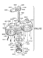
In an alternate embodiment, as shown in FIGS. 40 to 45 , transfer device 620 is an assembly having an upper housing 621, a lower housing 622 and a support post 641 received therebetween. Two substantially identical subassemblies 748 are assembled to, and retained by, upper housing 621 in generally equidistant, parallel and symmetric relationship with support post 641. Docking cups 660 are received in upper housing 621 in substantially parallel relationship with, and generally equidistant from, support post 641 and are seated in the upper housing by means of locking rim 628. Lower housing 622 interdigitates with docking cups 660 by means of registration notches 646. Support post 641 is received in the bottom guide 624 of lower housing 622 and retention opening 644 in the upper end 633 of upper housing 621. Support post 641 protrudes from the upper end of upper housing 621 to rotatably engage equipment support structure 200.
As previously described, docking cups 660 are substantially identical and comprise generally identical conical hollows 661, each having an elongated extension 673 to receive upper cone 710 of docking cone 700 in coaxial alignment, as more fully described below. Bottom openings 680 of docking cups 660 face downward and are positioned such that they are open to the outside for insertion of docking cones 700 without exposing security mechanism 720.
As shown in FIGS. 41 & 42 , docking cup 660 preferably is formed as a solid of revolution with an inner conical surface 665 shaped to coaxially receive frustoconical docking cone 700. The docking cup comprises a bottom contour 670 shaped to deflect misaligned insertion of cone tip 711 of upper cone 710; a security notch 694; and a feeler notch 664. Further, docking cup 660 preferably comprises a pivot 626 to pivotally attach security lever 721, thus constituting a self-contained subassembly 748 of a docking cup with integral, pivoting security lever, as shown in FIG. 41 . Two substantially identical subassemblies 748 are assembled to, and retained by, upper housing 621 in generally equidistant, parallel and symmetric relationship with post 641.
Each security lever 721 of security mechanism 720 comprises a security latch 726 that pivots from a first secured position to a second released position, or into and out of engagement with security engagement notch 709 of docking cone 700 to control retention of the docking cone in the respective docking cup of transfer device 620. Each security lever 721 also comprises a cone feeler 732 that causes the security latch 726 of said security lever 721 to pivot from a first secured position to a second released position in response to being displaced upward, against the bias of spring 747 (not shown), by the cone tip 711 of docking cone 700.
As shown in FIG. 45 , a cone arm 750 is attached to a stationary or mobile support platform. Cone arm 750 comprises arm structure 751, preferably an aluminum casting with, at its proximal end, a shaft 786 and at its distal end a docking cone 700 that is configured for docking engagement with docking cups 660 of transfer device 620. A spine 715 comprises upper cone 710, cone tip 711, inner bearing surface 718, and security engagement notch 709 and is attached to arm structure 751. As described above, the docking cone 700 has a security engagement notch 709 that cooperates with security latch 726 of security lever 721 to prevent or enable retention of docking cone 700, as the case may be, from docking cup 660.
It can also be seen in FIG. 41 that the security lever 721 has an offset 739 therein that creates a spaced apart relation that allows support post 641 to sit in the space created between the security levers 721. As a result, support post 641 can be positioned low in the transfer device 620 to achieve a low overall profile 650 of the transfer device 620 to accommodate attachment of more medical apparatus to the equipment support structure 200.
Turning now to FIG. 45 , an alternate arrangement of cone arm 150 and docking cone 100 is shown. Rotation of transfer device 20 about docking cone 100 tends to allow the uncontrolled rotation, or swing-out, of the transfer device during transport. To prevent said swing-out rotation, revolving cone 705 is configured to rotate about spine 715. The inner bearing surface 718 is in contact with spine 715 and may optionally be coated with damping grease to slow and control the rotation of revolving cone 705 relative to spine 715. However, the use of alternative damping means other than grease is within the scope of this specification.
A groove 714 provided in the outer bearing surface 712 of revolving cone 705 is filled with a friction material 717 that extends outwardly to contact inner conical surface 665 of docking cup 660. When transfer device 620 is received onto revolving cone 705, friction material 717 engages the inner conical surface 665 of docking cup 660 to prevent rotation of the transfer device 620 relative to outer bearing surface 712 of revolving cone 705. This engagement transfers the rotation of the transfer device 620 to the rotation-controlled interface between the inner bearing surface 718 and spine 715, thereby effectively controlling rotation and swing-out of the overall transfer device 620.
While there is shown and described herein certain specific structure embodying the invention, it will be manifest to those skilled in the art that various modifications and rearrangements of the parts may be made without departing from the spirit and scope of the underlying inventive concept and that the same is not limited to the particular forms herein shown and described.
As will be describe below in further detail, connecting link arm 4613 is joined to pole link arm 4612 by one or more fasteners that allow connecting link arm 4613 to rotate with respect to pole link arm 4612. Receiver arm 4614 is joined to connecting link arm 4613 by one or more fasteners that allow receiver arm 4614 to rotate with respect to connecting link arm 4613. In various embodiments, the aforementioned connections between the mounting pole 4611 and the pole link arm 4612, between the pole link arm 4612 and the connecting link arm 4613, and between the receiver arm 4614 and the connecting link arm 4613 allow a user to articulately move a receiver 4615 to any one of an infinite number of positions within a radius defined by the combined length of the pole link arm 4612, the connecting link arm 4613, and the receiver arm 4614. In various embodiments, receiver arm 4614 includes the receiver 4615. In various embodiments, the receiver 4615 is frustoconical in shape and may be also described as a cone.
The mobile support platform 4650 of FIG. 46 includes a receiver arm 4652 and a mobile support adapter 4651. In various embodiments, receiver arm 4652 includes a receiver 4615. In various embodiments, receiver 4615 can be incorporated into any one or more components of transfer system 4600 including, but not limited to stationary support platform 4610, mobile support platform 4650, and mobile stand-alone support platform 4670. In various embodiments, the receiver 4615 is frustoconical in shape and may be described as a cone. The frustoconical shape of receiver 4615 in the current embodiments is shown with angled side surface 4942′ (shown and identified in FIG. 59 ) in the current embodiment of mobile stand-alone support platform 4670 such that the angled side surface 4942′ is substantially flat in cross-section. As discussed below, various embodiments of the docking cone will include substantially scalloped or concave exterior side surfaces (as shown in FIG. 67 ).
In various embodiments, mobile support platform 4650 is configured to attach to or mount on a mobile platform such as a patient bed, gurney, wheelchair, ambulance, helicopter or other mobile platform between locations within or between medical facilities, such as intensive care rooms, operating rooms, radiology and other imaging facilities, catheterization labs, or between buildings and hospitals. Any mobile platform that includes a frame of sufficient strength and rigidity can be utilized. In various embodiments making use of a hospital bed 410, the mobile support platform 4650 is configured to attach to a frame of the hospital bed 410 via attachment of the lower end of mobile support platform 4650 to a portion of the frame of hospital bed 410.
The mobile stand-alone support platform 4670 of FIG. 46 is substitutable with stationary support platform 4610 or mobile support platform 4650 in various embodiments including medical environments where a stationary support platform or mobile support platform does not exist or is otherwise not available. Mobile stand-alone support platform 4670 includes a base 4672 and a support pole 4676 mounted to the base 4672 with a pole base 4675. Base 4672 includes central portion 4673 and a plurality of legs 4674—specifically five legs 4674 in the current embodiment although any number of legs 4674 may be present in various embodiments and the disclosure of five legs 4674 should not be considering limiting on the current disclosure. Attached to each leg 4674 with a fastener is a leg support 4671. In various embodiments, the leg support is a leg or a caster. In various embodiments, the leg support may incorporate the fastener or the fastening elements of the fastener such as the internal or external threads. The fastener may also take the form of one or more weldments or an adhesive. The presence of leg supports 4671 allows the mobile stand-alone support platform 4670 to be transported to and between those aforementioned environments where a stationary or mobile support platform does not exist or is otherwise not available. Once positioned, however, the mobile stand-alone support platform 4670 effectively becomes stationary by locking the leg supports 4671. In various embodiments, the locking feature is integral with the leg support although the disclosure of a locking feature that is integral with the leg support should not be considered limiting. Extending from base 4672 is the support pole 4676. The support pole 4676 includes a receiver 4615 at the top that in various embodiments is aligned axially with the support pole 4676. In various embodiments, no leg supports are required and base 4672 will sit flat on a horizontal surface such as a floor.
In various embodiments, the receiver—described in some embodiments as a docking cone—includes rotation-dampening features designed to lock or hinder the rotation of transfer apparatus 4630 with respect to receiver 4615 so as to prevent undesirable movement or rotation of transfer apparatus 4630 during movement of any of the support platforms 4650,4670, including in situations that require hospital bed 410, the mobile stand-alone support platform 4670, or another mobile platform to be moved. For example, in various embodiments the rotation-dampening feature prevents the transfer apparatus 4630 from swinging freely during movement of a hospital bed 410 as it is pushed down hospital hallways or around corners.
In various embodiments, attachment portion 4813 including threaded portion 4814 and cut 4815 are designed to mount on any one of a number of areas of the frame of a hospital bed 410 or any of a number of other aforementioned pieces of furniture or equipment. In various embodiments, nut 4720 secures mobile support adaptor 4651 to the equipment to which it is mounted after attachment portion 4813 has been inserted through a mounting hole (not shown) on such equipment. In various embodiments, an additional adaptor is utilized to connect mobile support adaptor 4651 to such equipment.
In addition to brake fastener 4860, arm brake mechanism 4730 includes a brake shaft 4820, a washer 4830, a pair of fasteners 4835 a,b, and a brake spacer 4850. In various embodiments, fasteners 4834 a,b are pins. In various other embodiments, one or more of fastener 4834 is any one of a group of fasteners including, but not limited to, a key or squared shaft. In various embodiments, the arm brake mechanism 4730 works in concert with the arm portion 4840 to prevent the rotation of or resist the rotation of receiver arm 4652 about mobile support adapter 4651. In various embodiments, brake shaft 4820 includes an upper portion 4821, a flange portion 4822, and a lower portion 4823. In various embodiments, brake shaft 4820 defines a bore 4824 and a pair of fastener bores 4825 a,b. In various embodiments, bore 4824 includes threads matching a threaded portion 4862 of brake fastener 4860. In various embodiments, fasteners bores 4825 a,b are sized to receive fasteners 4834 a,b. In various embodiments, each of fastener bores 4825 a,b is a straight-sided hole sized to fit fasteners 4835 a,b, respectively, and defined in and extending axially into upper portion 4821 of brake shaft 4820, far enough to fit at least a portion of the length of fasteners 4835 a,b. In various embodiments, one or more of fastener 4834 is integrally formed as part of brake shaft 4820 where one or more of fastener bore 4824 would otherwise be located. In various embodiments, one or more of fastener 4834 is integrally formed as part of brake spacer 4850 where one or more of a plurality of fastener bores 6010 a,b (shown in FIG. 60 ) of brake spacer 4850 would otherwise be located.
In various embodiments, brake fastener 4860 includes not only the threaded portion 4862 but also a fastener head 4865. In various embodiments, the fastener head 4865 includes a textured grip 5930. In various embodiments, the textured grip 5930 includes a knurled pattern. In various embodiments, the textured grip 5930 includes features that facilitate a grip on the fastener head 4865 for loosening and tightening the brake fastener 4860 with a reduced force. In various embodiments, the fastener head 4865 has a diameter as much as five to ten times a diameter of the threaded portion 4862 of the brake fastener 4860 for increased leverage—by an increase in a distance from the center of rotation at which the force is acting—and therefore less force is required to tighten the brake fastener 4860 to achieve the same tightening torque, though other diameter ranges may be present in various other embodiments. In various embodiments, the fastener head 4865—including the textured grip 5930—has a liquid-shedding and easily-cleanable design. In various embodiments, the fastener head 4865 is formed from a group of durable materials including, but not limited to, plastics, rubbers, and metals. In various embodiments, the fastener head 4865 is formed around threaded portion 4862 such that the one cannot rotate with respect to the other. In various embodiments, the fastener head 4865 is a knob.
In various embodiments, brake fastener 4860 includes a fastener head 4865 that includes a lever portion extending from threaded portion 4862 and a cam device where threaded portion 4862 and fastener head 4865 intersect. Like a quick-release lever on a wheel of a higher-end bicycle, the incorporation of the cam device effectively shortens the exposed length of the threaded portion 4862 when the lever portion is bent from a non-locking position to a locking position. Shortening the exposed length threaded portion 4862 effectively engages the arm brake without rotating threaded portion 4862. A user who rotates threaded portion 4862 about an axial center of threaded portion 4862, a step that can be desirable but it not required, simply adjusts the clamping force that is achieved once the lever portion is engaged. In various embodiments, the mechanical advantage created by the lever portion reduces the force (or torque in the case of a rotating fastener) required at the point of final engagement of brake fastener 4860—and arm brake mechanism 4730 by extension—which can be of benefit to users whose strength may be limited. In various embodiments, the use of a lever allows speedy and predictable tight engagement of the arm brake mechanism 4730.
As disclosed in FIG. 49 , the transfer system 4600 includes, at least in part, the transfer apparatus 4630, a first receiver arm 4614 a, and a second receiver arm 4614 b. In various embodiments, the transfer apparatus 4630 includes the transfer device 4631′, an offset arm 4634′, and the patient care apparatus 4632 including, in various embodiments, the pole 4633. In various embodiments, the transfer device 4631′ includes an upper housing 4920, a lower housing 4940, a support shaft 4996—also known as a support post—received therebetween, and a shaft brake mechanism 5200. In various embodiments, transfer device 4631′ includes a security mechanism 5010. In various embodiments, transfer device 4631′ is substantially symmetrical about a transverse plane of symmetry TP and substantially symmetrical about a longitudinal plane of symmetry LP with support shaft 4996 at the intersection of the transverse plane of symmetry TP and the longitudinal plane of symmetry LP. In various embodiments, the lower housing 4940 is received in the upper housing 4920 by a lip 5720 (shown in FIG. 57 ) at a joint line 4922. Support shaft 4996 is received in a bottom guide 5861 (shown in FIG. 58 ) of lower housing 4940 and in an upper guide 5750 (shown in FIG. 57 ) in the upper housing 4920. Support shaft 4996 protrudes from a shoulder 4921 of upper housing 4920 to engage a hub 4995 of offset arm 4634′. As shown in the portion of an embodiment of transfer device 4631′ shown in FIG. 52 , hub 4995 of offset arm 4634′ does not include the ball detents described as being in at least some embodiments of offset arm 4634. In various embodiments, offset arm 4634′ rotates with respect to transfer device 4631′.
Each receiver arm 4614 a,b is attached to a support platform such as the stationary support platform 4610, mobile support platform 4650, or mobile stand-alone support platform 4670. In various embodiments, a fastener 4950 secures a bushing (not shown) inside a bore 5085 of receiver arm 4614 so that receiver arm 4614 will rotate smoothly about that portion of transfer system 4600 about which receiver arm 4614 rotates without dislodging or causing the bushing to rotate with respect to receiver arm 4614. In various embodiments, the bushing is formed from any one of a number of materials including, but not limited to metals, plastics, or composites. In various embodiments where it is desired that receiver arm 4614 not rotate with respect to that portion of transfer system 4600 on which receiver arm 4614 is mounted (for example, a shaft similar to a hinge pin 6580 to which a receiver arm 4614″ is secured as in the stationary support platform 4610′ of FIG. 68 ), a fastener 4960 secures the receiver arm 4614 to the mount (not shown).
In various embodiments, a receiver 4615 includes any structure receivable by docking cup 5050. In various embodiments, a receiver 4615 includes any structure receivable by docking cup 5050 where the receiver includes a security engagement notch 4634. In various embodiments, a receiver 4615 includes any structure receivable by docking cup 5050 where the receiver includes a security engagement notch 4634 and a dome 820 capable of engaging cone feeler 5068 of security lever 5065 of security mechanism 5010.
As previously described in regard to other embodiments, docking cups 5050 a,b are substantially identical and generally symmetrical conical hollow structures defining inner surfaces 5054 a,b, respectively. In various embodiments, inner surfaces 5054 a,b may each also be described as a conical cavity. In various embodiments, docking cup 5050 includes an elongated extension 5057—extending upward from a neck plane 5051—to receive the upper portion 4933 of receiver 4615′ in coaxial alignment as more fully described below. A bottom opening defining a deflection edge 5045 of each docking cup 5050 faces downward and is positioned such that each docking cup 5050 is open to the outside for insertion of receiver 4615′ without exposing the security mechanism 5010.
The deflection edge 5045 at the bottom opening of docking cup 5050 is shaped to deflect misaligned insertion of dome 820 of upper portion 4933 of receiver 4615′. Because the deflection edge 5045 has a rounded shape, a misaligned dome 820 of receiver 4615′ will deflect towards the inside of the docking cup 5050 or will deflect away from transfer device 4631′ if significantly misaligned. In various embodiments, the shape of deflection edge 5045 is asymmetric such that dome 820 of receiver 4615′ will be deflected into docking cup 5050 as long as the tip of the receiver in contact with transfer device is inboard from a radially-outermost exterior surface of docking cup 5050. In various embodiments, each docking cup 5050 includes a security aperture 5849 (shown in FIG. 58 ), which permits passage of a latch tip 5066 of a security latch 5080. In various embodiments, each docking cup 5050 includes a feeler notch 5848 (also shown in FIG. 58 ), which permits the cone feeler 5068 of security lever 5065 to drop down into throat 5057 of docking cup 5050—as far as to the bottom of feeler notch 5848 in various embodiments—when no receiver is docked so that the security latch 5080 engages the receiver 4615′ docked inside the neighboring docking cup 5050, thereby preventing the removal of receiver 4615′ until security latch 5080 is no longer engaged. In various embodiments, each docking cup 5050 includes an inner wall 5041 and an outer wall 5042. Extension 5057 of each docking cup 5050 also includes a throat 5550 (shown in FIG. 55 ), which includes a throat inner surface 5052 defining a throat clearance diameter D1 at neck plane 5051. An upper end of the outside of extension 5057 defines an outside diameter D2.
In various embodiments, upper housing 4920 is attached to lower housing 4940 with a plurality of fasteners 5241. In various embodiments, fastener 5241 will be a non-magnetic, stainless steel thread-forming screw including a triangular (or tri-lobular) shank to ensure a vibration-resistant connection in plastic, though the screw may be other materials in various embodiments. This type of screw is also known as a PLASTITE screw, described as having “coarse, sharply angled threads and a blunt tip.” See, e.g., Item 96001A326 available from McMaster-Carr Supply Company. The aforementioned catalog describes the screw as providing “maximum holding strength with minimal stress in formable plastics such as polypropylene and polycarbonate.” In various embodiments, the head of fastener 5241 will include a TORX recess in order to increase the tamper resistance of transfer apparatus 4630 and specifically transfer device 4631′ by requiring a special tool for disassembly. However, the disclosure of a stainless-steel tri-lobular screw with a TORX head should not be considered limiting. In various embodiments, the upper housing 4920 and lower housing 4940 can be connected using one of a group of other attachment methods including, but not limited to, other threaded or non-threaded fasteners, weldments, plastic snap joints, and adhesives.
Further, docking cup 5050 defines a pivot slot 5056 that allows security lever 5065 to pivot about a pair of pivot pins 5475 upon movement of cone feeler 5068 away from docking cup 5050 and towards interior top cavity 5027 defined in upper housing 4920. Each security lever 5065 of security mechanism 5010 includes the security latch 5080 with the latch tip 5066 that pivots from a first secured position (e.g., the position of security latch 5080 b of security lever 5065 b in FIG. 50 ) to a second released position (e.g., the position of security latch 5080 a of security lever 5065 a in FIG. 50 ). The movement of security latch 5080 brings latch tip 5066 into and out of engagement with security engagement notch 4934 of receiver 4615′ to control retention of receiver 4615′ in the respective docking cup 5050 of transfer device 4631′. The cone feeler 5068 of each security lever 5065 causes the security latch 5080 of said security lever 5065 to pivot from a first secured position to a second released position in response to being displaced upward by the cone tip 711 of docking cone 700. In various embodiments, security lever 5065 is displaced upward against the bias of biasing element 5579 (shown in FIG. 55 ) or the bias of biasing element 5879 (shown in FIG. 58 . In various embodiments, a biasing element is incorporated into security lever 5065. In various embodiments such as shown in a security lever 5065′ of FIG. 54d , a biasing element is integrally formed with security lever 5065,5065′.
In various embodiments, the security mechanism 5010 is enclosed within the transfer device 4631′. In various embodiments, the security mechanism 5010 includes a first security lever 5065 a and a second security lever 5065 b, the first security lever 5065 a positioned to disengage a first receiver 4615 a′ in the first docking cup 5050 a when a second receiver 4615 b′ is received within the second docking cup 5050 b, and the second security lever 5065 b positioned to disengage the second receiver 4615 b′ in the second docking cup 5050 b when the first receiver 4615 a′ is received within the first docking cup 5050 a. In various embodiments, the security levers 5065 a,b default to a position where the cone feelers 5068 a,b, respectively, drop to the lowest position when no docking cone or receiver 4615′ is inserted into the transfer device. In various embodiments, the default position is ensured by the presence of a biasing element such as biasing element 5579 (shown in FIG. 55 ) or biasing element 5879 (shown in FIG. 58 ) engaging each security lever 5065 so as to bias the cone feelers 5068 a,b in the downward direction. In various embodiments, the default position is ensured by the force of gravity, by a magnetic force, or by another force acting on each of security levers 5065 a,b.
In various embodiments, each docking cup 5050 includes a plurality of rotation-dampening elements 5110 for use in restraining or restricting or dampening the rotational movement of transfer device 4631′ with respect to receiver 4615′. Rotation of transfer apparatus 4630 about receiver arm 4614 tends to allow the uncontrolled rotation, or swing-out, of the transfer apparatus 4630 during transport. In various other embodiments, no such element or only one such rotation-dampening element 5110 exists. In various embodiments, each of rotation-dampening elements 5110 has a flattened end.
Any one or more of the following specifications of the rotation-dampening element(s) 5120, 5110,5110′ can be adjusted to increase the dampening effect:
1. Material
2. Quantity
3. Spacing
4. Relief depth d1 (measured from angled side surface 4942)
5. Longitudinal radius R1
6. Latitudinal radius as measured in a horizontal plane (not shown)
7. Protruding distance d2
8. Diameter D3
9. Length L1
10. Shape of edge 5112 (including size of tip radius R2 in some embodiments)
11. Material of docking cup inner surface 5054
12. Wall thickness t
13. Wire diameter D4
14. Angles A1 and A2
The above list is not an exhaustive list of the various methods for adjusting the dampening effect of the rotation-dampening elements. Additional materials and structures could be used to achieve a similar dampening effect including, but not limited to plastic springs molded into either the wall of docking cup 5050 or receiver 4615′ or both or the use of flexible pawls like pawl 6570 shown incorporated into receiver 4615″ in FIG. 68 . In various embodiments where the rotation-dampening element is assembled to the inside of the docking cup 5050, crevices in receiver 4615′ that could increase the difficulty of cleaning receiver 4615′ will be minimized or eliminated.
In various embodiments, the transfer device 4631′ including security mechanism 5010 can support the load applied when someone or something uses the transfer device 4631′ to lift up at least some of the weight of the hospital bed 410 or other movable structure to which receiver arm 4614 a′ is attached. In various circumstances, someone or something lifts up the transfer device 4631′ while security latch 5080 b is engaged with security engagement notch 4934 a of receiver 4615 a′ thereby preventing removal of receiver 4615 a′ from transfer device 4631′. In various circumstances, security latch 5080 b is engaged with security engagement notch 4934 a of receiver 4615 a′ specifically when locking receiver 4615 a′ is locked into docking cone 5050 a but receiver 4615 b′ is not locked into docking cone 5050 b. In such circumstances, security latch 5080 b will bear some or all of the weight of the hospital bed 410 or other movable structure to which receiver 4615′ is attached. At such times, a lower surface 5140 b of the security latch 5080 contacts a lower edge surface 5150 a of security aperture 5849 a and an upper edge 5067 a of the security latch 5080 contacts a lower edge surface 5160 a of upper portion 4933 a of receiver 4615′ of receiver arm 4614 such that the transfer device 4631 supports the load represented by the force F2′. In various embodiments, each security lever 5065 will be shaped in such a way and made of such a material having sufficient strength to support the shear load that will act on security lever 5065 and particularly security latch 5080 in such circumstances as described.
In various embodiments, the security lever 5065 defines a curvature of the lower surface 5140 having a radius R3 (shown in FIG. 54d ) which may be slightly smaller than but which substantially complements a radius (not shown) of the lower edge surface 5150 of the security aperture 5849 of the lower housing 4940 of the transfer device 4631′. In various embodiments, the lower surface 5140 and the lower edge surface 5150 are thus in a co-radial relationship. In normal operation of the transfer system 4600, a small gap exists between the lower surface 5140 of the security latch 5080 and the lower edge surface 5150 of the security aperture 5849; in various embodiments, this gap allows for free movement of the security latch 5080 without any encumbrance due to the sliding of lower surface 5140 on the lower edge surface 5150. When loading of the transfer device 4631′ causes the security latch 5080 to be pushed towards the lower edge surface 5150, the small gap between the lower surface 5140 and the lower edge surface 5150 closes such that the lower surface 5140 bears against lower edge surface 5150 and is supported thereby in various embodiments. In various embodiments, the use of a glass-reinforced polymer material, metal, or another material for security lever 5065, the use of vertical ribs in security latch 5080 where contact is made with security aperture 5849 and receiver 4615′, or both, will successfully support the described load. See FIG. 54c for additional description of the security lever 5065.
In various embodiments, shaft brake mechanism 5200 includes a combination of any one or more of plates, brake pads, spacers, and brake fasteners. In various embodiments, some of the components of shaft brake mechanism 5200 are assembled to each other to form shaft brake assembly 6200 (shown in FIG. 62 ) before assembling shaft brake mechanism to transfer device 4631′. In the current embodiment, shaft brake mechanism 5200 includes an upper plate 6220, a middle plate 6230, a lower plate 6240, a pair of brake pads 5220, a plurality of standoff fasteners 6300, and a brake fastener 5240. In various embodiments, upper plate 6220, middle plate 6230, and lower plate 6240 are shown with bores 6225, bore 6235, and bore 6245, respectively. In various embodiments, brake pads 5220 include an anti-rotation cutout 5225. In various embodiments, brake fastener 5240 includes a threaded portion 5242, a knurled portion 5244, and a standoff portion 5246. In various embodiments, the lower housing 4940 is formed with a parting line 4911, although the location of the parting line is not limited to that shown.
When engaged by tightening brake fastener 5240, shaft brake mechanism 5200 fixes the rotational position of support shaft 4996—and by extension the patient care apparatus 4632—by fixing the rotational position of one or more brake pads 5220. Fixing the rotational position of one or more of brake pads 5220 is made possible by coupling each brake pad 5220 to support shaft 4996 by the use of the “double-D” anti-rotation cutout 5225. In various embodiments, anti-rotation cutout 5225 in each of brake pads 5220 matches the cross-sectional shape of support shaft 4996 at the lower end where support shaft 4996 defines a pair of flats 5290. In various embodiments, tightening brake fastener 5240 results in increased pressure between one or more brake pads 5220 and middle plate 6230. Such increased pressure between each of the parts and particularly at the surfaces of each of the brake pads 5220 increases the coefficient of friction and therefore the resistance to rotational movement—of the brake pads 5220 and therefore also the support shaft 4996 to which the brake pads 5220 are coupled.
In various other embodiments, more components or fewer components are present to accomplish the braking function. In various embodiments, brake fastener 5240 includes a lever portion extending from threaded portion 5242 and a cam portion proximate to the intersection between threaded portion 5242 and the lever portion. Bending the lever effectively translates the threaded portion 5242 without rotating threaded portion 5242. In various embodiments, the mechanical advantage created by the lever portion reduces the force (or torque in the case of a rotating fastener) required at the point of final engagement—which can be of benefit to users whose strength may be limited—and allows speedier, if not instant, engagement of the shaft brake mechanism 5200. In various embodiments, the structure and function is similar to that of the aforementioned bicycle wheel quick-release lever.
In various embodiments, the offset arm spacing S3 and the offset arm spacing S4 of each arm 5392 a,b, respectively, of multi-pole offset arm 5390 is dimensioned to position the center of gravity of the patient care device 4638 or the center of gravity of the patient care apparatus 4632 substantially over the support shaft 4996 such that the center of gravity of either the patient care device 4638 or the center of gravity of the patient care apparatus 4632 is aligned vertically with the center of the support shaft 4996 along axis 5320. In various embodiments, the substantial vertical alignment of the center of gravity of the patient care apparatus 4632 with the support shaft 4996 along a vertical axis such as the axis 5320 reduces the tendency of the patient care apparatus 4632 or the transfer device 4631′ to lean at an angle from the vertical. Maintaining the patient care apparatus 4632 in a vertical orientation can yield various functional and aesthetic benefits. Maintaining the patient care apparatus 4632 in a vertical orientation can also further improve the reliability of not only individual components of the transfer system 4600 but also the transfer system 4600 as a whole, in some cases reducing the wear experienced by various components by limiting the side loads acting between the support shaft 4996 and the upper housing 4920 and between the support shaft 4996 and the lower housing 4940.
In various embodiments, each of the components of transfer system 4600 including transfer device 4631′ and the biasing element and are made from magnetic-resonance-safe or magnetic-resonance-imaging-safe (MR-safe or MRI-safe, respectively) materials. Materials that are MR-safe can be selected from a group including, but not limited to, plastic, composites, aluminum, non-ferritic (typically non-magnetic) stainless steels and other non-non-magnetic or non-ferrous metals that are not adversely affected by or that do not adversely interfere with an environment utilizing magnetic-resonance technology. In various embodiments, the security levers 5065 are at least initially formed of an extruded shape. In various embodiments, the security levers 5065 are formed into a molded or cast shape using an additive manufacturing process, wherein additive manufacturing processes include, but are not limited to, injection molding, casting, and three-dimensional printing. However, the disclosure of an additive manufacturing process should not be considered limiting. In various embodiments, the security levers 5065 are molded from a polymer material.
In various embodiments, the brake spacer 4850 is coupled to the brake shaft 4820. In various embodiments, the brake spacer 4850 is coupled to the brake shaft 4820 with fasteners 4835 a,b. In various embodiments, fasteners 4835 a,b are inserted into fastener bores 4825 a,b of brake shaft 4820 and are inserted into fastener bores 6010 a,b of brake spacer 4850 to prevent the rotation of brake spacer 4850 with respect to brake shaft 4820. In various embodiments, coupling the brake spacer 4850 to the brake shaft 4820 with fasteners 4834 a,b and contacting arm portion 4840 with brake spacer 4850 fixes arm portion 4840 while reducing the risk of brake fastener 4860 loosening simply by the forced rotation of arm portion 4840 when arm brake mechanism 4730 has been tightened. In various embodiments, only one fastener 4834 coupled with one bore 4824 is required to prevent this loosening.
In various embodiments, a gap G1 is defined by the distance between upper surface 6242 of lower plate 6240 and lower surface 5221 of the lowermost brake pad 5220. In various embodiments, a gap G2 is defined by the distance between an upper surface 5222 of the uppermost brake pad 5220 and the lower surface 6221 of the upper plate 6220. In various embodiments, a gap G3 is defined by the distance between the upper surface 6222 of upper plate 6220 and the uppermost portion of surface 7010 of the lower housing 4940. In various embodiments, gap G2 and gap G3 are reduced to zero to reduce the vertical movement of support shaft 4996 and therefore also patient care apparatus 4632′. In various embodiments, gap G1 is maintained to allow the free rotational movement of support shaft 4996 when shaft brake mechanism 5200 is not engaged.
In various embodiments, the amount of frictional force generated by a specific brake fastener torque (as applied to brake fastener 5240, for example) can be adjusted by changing the material of middle plate 6230 or the brake pads 5220. In various embodiments, both middle plate 6230 and the brake pads 5220 are rigid enough not to deform even when the shaft brake mechanism 5200 is engaged and therefore causing various forces to act on each. In various embodiments, this frictional force can be adjusted by changing the contact surface area between middle plate 6230 and the brake pads 5220. In various embodiments, this frictional force can be adjusted by adjusting other factors including the ease at which the brake fastener 5240 can be tightened. If the force required to engage the brake is decreased, this effectively increases the frictional force generated should the applied force remain constant. Individual parts of the shaft brake assembly 6200 or the various other embodiments thereof can be serviced or the subassembly replaced as a whole as described previously. In various embodiments, recesses (not shown) will be created in lower housing 4940 to create space for the heads of fasteners 6310 of shaft brake assembly 7000 or to provide an attachment point for the aforementioned biasing elements 5879 a,b. In various embodiments, both functions can be accomplished in the same structure by locating the attachment bosses 5863 a,b coaxial with fasteners 6310. In various embodiments, the brake fastener 5240 is adapted to be tightened or is tightenable by hand without the necessity for tools. In various embodiments, the brake fastener 5240 includes a knob. The design of the knurled portion 5244 of the knob 5240 can facilitate hand tightening by the incorporation of features that allow a user's fingers to rotate the knob with only a minimal percentage of the applied force required to keep the user's fingers from slipping on the knob.
In various embodiments, a shaft brake mechanism (not shown) can be created from shaft brake assembly 6200 by removal of lower plate 6240 and standoff fasteners 6300. While both embodiments will function in the same way during use, the shaft brake assembly 6200 is installed and removed as a subassembly while the components of the shaft brake mechanism without lower plate 6240 and standoff fasteners 6300 can be removed individually as loose parts. As previously described in relation to shaft brake assembly 5200, it will benefit the end user or maintenance person in various embodiments to be able to quickly replace the shaft brake assembly 7000 without risk of losing small parts or reinstalling them incorrectly. In various other embodiments, the benefits of the shaft brake mechanism requiring fewer parts will outweigh the service benefits.
In various embodiments, only one brake pad 5220 is utilized in the shaft brake mechanism. In various embodiments, fewer components are used to accomplish the shaft-braking function. In various embodiments, shaft brake fastener 5240 and a single brake pad 5220 are used in combination with a shortened support shaft 4996 that protrudes a distance below an uppermost portion of surface 7010 that is no more than the thickness of a single brake pad 5220. In such an embodiment, the shaft brake fastener 5240 tightens the brake pad 5220 directly against the uppermost portion of surface 7010 of transfer device 4631′ to create the desired resistance to rotational movement of brake pad 5220 and therefore also support shaft 4996 and the patient care apparatus 4632. In various embodiments, neither shaft brake assembly 7000 nor shaft brake assembly 6200 is required at all as brake fastener will sufficiently tighten against lower housing 4940, causing surface 7010 of lower housing 4940 to serve either directly or indirectly as a brake pad to resist rotational movement of offset arm 4634′ and the patient care apparatus 4632 with respect to transfer device 4631′. As disclosed in FIG. 62b , in various embodiments, the upper brake pad 5220 is compressed against the surface 5295 adjacent the flat 5290 of the shaft 4996 by the shoulder 5246 of the knob 5240. In various embodiments, the surface 5295 is parallel to the brake pad 5220, at least when the brake pad 5220 is compressed against the surface 5295.
In various other embodiments, the receiver arm 4614—including any of the aforementioned shape variations—is integrally molded, cast, machined or otherwise formed in one piece and fasteners are not required to assemble and maintain the integrity of the component. For the purposes of the current disclosure, to be “integrally-formed” or “integrally formed” means to be molded or shaped into a single part during the forming process and to be a “unitary” part means to remain a single indivisible homogeneous part throughout the forming process.
As described above and shown in FIG. 68 , flexible pawls such as pawl 6570 can be incorporated into receiver 4615′ in FIG. 46 and receiver 4615″ in FIG. 68 . In various embodiments where pawl 6570 is used as a rotation-dampening element, protruding portion 6576 of pawl 6570 engages with features (not shown) inside a docking cup 5050′ that will resist movement of the receiver 4615″ with respect to the docking cup 5050′. In various embodiments, these features include a plurality of detents (not shown) defined in each docking cup—detents into which one or more pawls can engage but also disengage under sufficient force to push protruding portion 6576 clear of inside surface 5054 of docking cup 5050. In various embodiments, the features into which pawls 6570 engage allow transfer device 4631′ to rotate with respect to receiver 4615″ when transfer device 4631′ is pushed or pulled by hand with sufficient force but prevent transfer device 4631′ from swinging wildly or freely on its own during use. In various embodiments, each of these detents resembles relief 4943 but are defined in the inside surface 5054 of docking cup 5050. In various embodiments, the depth of each of these detents or the radius—including the radii at both the entrance and exit of the detent—can be adjusted to increase the force necessary to rotate the transfer device 4631′. In various embodiments, transfer device 4631′ can be rotated by hand about receiver 4615″ (or any other compatible receiver) with sufficient force but is prevented from swinging wildly. As shown in FIG. 68 , the structure of pawl 6570 with a base portion 6572 and a flex portion 6575 allows movement of protruding portion 6576 away from the inside of the docking cup 5050′ when the torque is sufficient high.
In various embodiments, the plate 6820 helps maintain the integrity of the transfer device 6800 by helping lock the two housing halves 6810 a,b (shown in FIG. 71 ) together with a plurality of fasteners 6830 to close a housing seam 6811. The plate 6820 also provides a wide, flat surface 6821 on which a hub 6995 of the offset arm 4634″ can rotate. In various embodiments, the hub 695 of offset arm 4634″ defines one or more holes in which a fastener 6970—in various embodiments a set screw—secures offset arm 4634″ to shaft 6996. In various embodiments, the plate 6820 defines a hole 6840 in the center to provide clearance for the shaft (not shown) to which the offset arm 4634″ is connected).
In various embodiments, the thickness and diameter of plate 6820 may vary depending on the load that is to be supported and other factors. In various embodiments, the plate 6820 can be secured to the housing 6810 by a different type of fastener or quantity of fasteners than the plurality of fasteners 6830 shown. In various embodiments, one or more fasteners oriented in a plane parallel to and not perpendicular to the surface 6821 as shown, attach the plate 6820 to the housing 6810 by engaging one or more side surfaces (not shown) of the housing 6810 and a surface (not shown) of the plate 6820. In various such embodiments, the plate 6820 may have vertical flanges defining threads or one or more holes or keyhole slots for the purpose of attaching the plate 6820 to the housing 6810. The plate 6820 may resemble a cap in various embodiments.
In various embodiments, the washer 6960 separates the hub 6995 of offset arm 4634″ from plate 6820 in order to prevent metal-to-metal contact. In various embodiments, holes 6940 on each side of housing 6810 are sized to fit a plurality of elongated-tip fasteners 6945 (shown in FIG. 71 ) to prevent a sleeve 6850 (shown in FIGS. 70-72 ) internal to the housing 6810 from sliding vertically, moving side to side, or rotating during rotation of the offset arm 4634″. In various embodiments, the fasteners 6945 are 5/16-24 set screws (i.e. 5/16″ in nominal diameter, twenty four threads per inch, with an internal hex head, and of various lengths as measured from the base of the head to the tip of the fastener). The disclosure of a specific style or size of fastener 6945, however, should not be considered limiting. In various embodiments, one or more of fasteners 6945 includes a knob 6950.
In part, FIG. 73 discloses the single-pole version of the patient care apparatus kit 7200 as assembled. In various embodiments, the patient care apparatus kit 7200 includes a patient care apparatus 4632′, the plate 6820, the shaft 6996, and various other components previously described as being included in the patient care apparatus kit 7200. In various embodiments, the patient care apparatus 4632′ includes an offset arm 4634″ and a pole 4633 that is an IV pole in the current embodiment. In various embodiments, the patient care apparatus 4632′ includes a top portion 4635′ and adjustment knob 4637 to allow the top portion 4635′ to be raised or lowered with respect to the pole 4633. In various embodiments, top portion 4635′ includes hooks 4636, shown in a different configuration than that shown in the top portion 4635 of FIG. 46 . As previously noted, hooks 4636 can take on any number of different shapes and are not limited to the “rams-horn” style shown. In various embodiments, the quantity and placement of hooks 4636 varies from that shown. In various embodiments, offset arm 4634″ includes ball detents (not shown) similar to ball detents 5394 shown in FIG. 53 in order to increase the resistance against rotation of offset arm 4634″ or to provide set angular positions at which offset arm 4634″ can be “indexed” or rotated in pre-set increments. In various embodiments, resistance against rotation of offset arm 4634″ is accomplished by incorporating a brake mechanism such as the shaft brake mechanism 5200 shown in transfer device 4631′.
In part, FIG. 73 also discloses a multi-pole version of the patient care apparatus kit in the embodiment of a patient care apparatus kit 7300. In various embodiments, the patient care apparatus kit 7300 includes a patient care apparatus 4632″ and the same components previously described as being included in the patient care apparatus kit 7200 with the exception of offset arm 4634″ and the components connecting offset arm 4634″ to pole 4633. In various embodiments, the patient care apparatus 4632″ includes an offset arm 4634′″ and a lower rail 7310 secured to offset arm 4634′″ with one or more fasteners 7330—countersunk in the current embodiment. In various embodiments, the patient care apparatus 4632″ additionally includes a plurality of poles 4633, each connected to the lower rail 7310 and to an upper rail 7310′ using a plurality of connectors. In various embodiments, connectors 7320 are slidably attached to rail 7310,7310′ and locked to the rails by set screws at the desired spacing of poles 4633. Two or more poles can thus be attached to rails 7310,7310′. In various embodiments, a shelf 7350 is placed on the top surface of an offset arm such as the offset arm 4634′″ and in some embodiments fastened by screws or other mechanisms known in the art in order to provide a temporary support during installation of the patient care device 4638 to poles 4633 or rails 7310,7310′ of a patient care apparatus such as the patient care apparatus 4632′″ so as to help users to install the patient care device 4638 patient care apparatus so that the center of gravity of the patient care device 4638 is centered approximately over the axis of support shaft 6996. The shelf 7350 may be made of an opaque or translucent material but in various embodiments is made from a material that is easily cleanable. In various embodiments, the shelf 7350 is removable from the patient care apparatus 4632′″ including for cleaning.
In various embodiments, the patient care apparatus 4632″ additionally includes the top portion 4635′ and adjustment knob 4637 to allow the top portion 4635′ to be raised or lowered with respect to the remaining portion of the patient care apparatus 4632″. In various embodiments, top portion 4635′ includes hooks 4636. In various embodiments, the quantity and placement of rails 7310,7310′, poles 4633, connectors 7320, or top portions 4635′ including hooks 4636 varies from that shown. By changing the length or position of one or more of the aforementioned components of the patient care apparatus 4632″, various types of equipment can be secured to the patient care apparatus 4632″.
In the current embodiment, the end of offset arm 4634′″ distal to where shaft 6996 is attached includes a vertical surface in which holes (not shown) are defined and in which fasteners 7330 are secured. In various embodiments, offset arm 4634′″ includes ball detents (not shown) similar to ball detents 5394 shown in FIG. 53 in order to increase the resistance against rotation of offset arm 4634′″ or to provide set angular positions at which offset arm 4634′″ can be “indexed” or rotated in pre-set increments. In various embodiments, resistance against rotation of offset arm 4634′″ is accomplished by incorporating a brake mechanism such as the shaft brake mechanism 5200 shown in transfer device 4631′.
In various embodiments, one or more features or elements of the patient care apparatus 4632′ or 4632″ are incorporated into transfer system 4600 with transfer device 4631 or 4631′. Because the offset arm 4634′,4634″,4634′″ can vary between various embodiments of various parts of transfer system 4600, various embodiments of the patient care apparatus 4632,4632′,4632″ can be coupled with various embodiments of transfer device 4631,4631,6800 and various other transfer devices including transfer devices of an older design that are already in use by customers.
In various embodiments where the transfer system 4600 includes a transfer device 4631′, the transfer device 4631′ includes the support shaft 4996 and a shaft brake mechanism 5200 including shaft brake assembly 6200. In various embodiments, a shaft brake mechanism (not shown) will include the embodiment reflected in shaft brake assembly 7000. In various embodiments, the shaft brake mechanism 5200 is engageable with the support shaft 4996, a method of using the transfer system 4600 includes disengaging the shaft brake mechanism 5200 by hand; rotating the support shaft 4996; and re-engaging the shaft brake mechanism 5200 by hand. In various embodiments where the transfer system 4600 further includes a receiver arm 4614 attachable to a mobile support platform 4650 and receivable by the transfer device 4631′ and an arm brake mechanism 4730 engageable with an arm portion 4840 of the receiver arm 4652, the method further includes disengaging the arm brake mechanism 4730 by hand, rotating the arm portion 4840; and re-engaging the arm brake mechanism 4730 by hand. In various embodiments where the transfer device 4631′ is mounted to a mobile support platform 4650, the method further includes maintaining the angular orientation of the transfer device 4631′ relative to the mobile support platform 4650 while moving the mobile support platform 4650. In various embodiments where the receiver arm 4652 includes a receiver 4615′ and the receiver includes a plurality of pawls 6570, the method further comprises rotationally dampening the receiver arm 4652 within a docking cup 5050 of the transfer device 4631′.
While there is shown and described herein certain specific structure embodying the invention, it will be manifest to those skilled in the art that various modifications and rearrangements of the parts may be made without departing from the spirit and scope of the underlying inventive concept and that the same is not limited to the particular forms herein shown and described.
One should note that conditional language, such as, among others, “can,” “could,” “might,” or “may,” unless specifically stated otherwise, or otherwise understood within the context as used, is generally intended to convey that certain embodiments include, while other embodiments do not include, certain features, elements and/or steps. Thus, such conditional language is not generally intended to imply that features, elements and/or steps are in any way required for one or more particular embodiments or that one or more particular embodiments necessarily include logic for deciding, with or without user input or prompting, whether these features, elements and/or steps are included or are to be performed in any particular embodiment.
It should be emphasized that the above-described embodiments are merely possible examples of implementations, merely set forth for a clear understanding of the principles of the present disclosure. Any process descriptions or blocks in flow diagrams should be understood as representing modules, segments, or portions of code which include one or more executable instructions for implementing specific logical functions or steps in the process, and alternate implementations are included in which functions may not be included or executed at all, may be executed out of order from that shown or discussed, including substantially concurrently or in reverse order, depending on the functionality involved, as would be understood by those reasonably skilled in the art of the present disclosure. Many variations and modifications may be made to the above-described embodiment(s) without departing substantially from the spirit and principles of the present disclosure. Further, the scope of the present disclosure is intended to cover any and all combinations and sub-combinations of all elements, features, and aspects discussed above. All such modifications and variations are intended to be included herein within the scope of the present disclosure, and all possible claims to individual aspects or combinations of elements or steps are intended to be supported by the present disclosure.
Claims (20)
1. A transfer device for a patient care apparatus comprising:
a first docking cup and a second docking cup, each of the first docking cup and the second docking cup aligned with a vertical axis, defining a conical surface aligned with the vertical axis, and sized to receive a receiver;
a security mechanism enclosed within the transfer device;
a support shaft disposed between the first docking cup and the second docking cup; and
a shaft brake mechanism engageable with the support shaft, at least a portion of the shaft brake mechanism disposed below the support shaft and disposed between the first docking cup and the second docking cup.
2. The transfer device of claim 1 , further comprising an offset arm coupled to the support shaft.
3. The transfer device of claim 1 , wherein the shaft brake mechanism comprises a brake disc, a plate, and a brake fastener, the brake fastener configured to increase a force holding the brake disc to the plate when the brake fastener is tightened.
4. The transfer device of claim 3 , wherein the brake fastener comprises a knob.
5. The transfer device of claim 3 , wherein the brake disc, the plate, and the brake fastener are aligned along a common axis.
6. A transfer device for a patient care apparatus comprising:
a first docking cup and a second docking cup, each of the first docking cup and the second docking cup aligned with a vertical axis, defining a conical surface aligned with the vertical axis, defining an opening facing downward, and sized to receive a receiver; and
a security mechanism enclosed within the transfer device.
7. The transfer device of claim 6 , wherein the first docking cup comprises a rotation-dampening element.
8. The transfer device of claim 7 , wherein the rotation-dampening element is replaceable.
9. The transfer device of claim 6 , further comprising a support shaft and a shaft brake mechanism engageable with the support shaft, the shaft brake mechanism comprising a brake fastener that is tightenable, the brake fastener comprising a knob.
10. The transfer device of claim 6 , further comprising a support shaft and a multi-pole offset arm, the support shaft disposed between the first docking cup and the second docking cup of the transfer device, the multi-pole offset arm coupled to the support shaft.
11. The transfer device of claim 6 , further comprising a support shaft and an offset arm and a patient care device, the support shaft disposed between the first docking cup and the second docking cup of the transfer device, the offset arm coupled to the support shaft, and an offset arm spacing of the offset arm such that a center of gravity of the patient care apparatus is substantially aligned with a support shaft of the transfer device.
12. A transfer system for a patient care apparatus comprising:
a receiver arm; and
an arm brake mechanism, the arm brake mechanism comprising a brake shaft, a brake spacer, and an arm brake fastener, the brake spacer coupled to the brake shaft and configured to rotate together with the brake shaft.
13. The transfer system of claim 12 , further comprising a receiver, a surface of the receiver defining a relief and the rotation-dampening element extending radially inward from the inner surface of the docking cup.
14. The transfer system of claim 12 , further comprising a receiver, a one of the receiver and the receiver arm integrally formed as a single part.
15. The transfer system of claim 12 , wherein the brake spacer is coupled to the brake shaft with a removable fastener.
16. The transfer system of claim 12 , wherein the brake spacer comprises a conical surface, the receiver arm comprises a conical surface, and the arm brake fastener comprises a threaded portion, the conical surface of the brake spacer, the conical surface of the receiver arm, and the threaded portion of the arm brake fastener being coaxial.
17. A method of using a transfer system, the method comprising:
engaging a receiver of the transfer system with a transfer device of the transfer system, the transfer device comprising a first docking cup, a second docking cup, a support shaft, and a shaft brake mechanism engageable with the support shaft, the support shaft disposed between the first docking cup and the second docking cup and at least a portion of the shaft brake mechanism disposed below the support shaft and disposed between the first docking cup and the second docking cup;
disengaging the shaft brake mechanism by hand;
rotating the support shaft; and
re-engaging the shaft brake mechanism by hand.
18. The method of claim 17 , further comprising maintaining the position of the transfer device relative to a mobile support platform while moving the mobile support platform, the transfer device mounted to the mobile support platform.
19. The method of claim 17 , wherein the shaft brake mechanism comprises a brake disc, a plate, and a brake fastener, wherein re-engaging the shaft brake mechanism comprises increasing a force holding the brake disc against the plate by tightening the brake fastener.
20. The method of claim 17 , wherein the receiver arm comprises a receiver and the receiver comprises a plurality of pawls, the method further comprising rotationally dampening the receiver arm within a one of the first docking cup and the second docking cup of the transfer device.
Priority Applications (1)
| Application Number | Priority Date | Filing Date | Title |
|---|---|---|---|
| US15/347,070 US9827062B2 (en) | 2010-05-10 | 2016-11-09 | Secure equipment transfer system |
Applications Claiming Priority (5)
| Application Number | Priority Date | Filing Date | Title |
|---|---|---|---|
| US33291810P | 2010-05-10 | 2010-05-10 | |
| US13/104,531 US8579244B2 (en) | 2010-05-10 | 2011-05-10 | Secure equipment transfer system |
| US14/064,345 US9404616B2 (en) | 2010-05-10 | 2013-10-28 | Secure equipment transfer system |
| US14/686,439 US9528536B2 (en) | 2010-05-10 | 2015-04-14 | Secure equipment transfer system |
| US15/347,070 US9827062B2 (en) | 2010-05-10 | 2016-11-09 | Secure equipment transfer system |
Related Parent Applications (1)
| Application Number | Title | Priority Date | Filing Date |
|---|---|---|---|
| US14/686,439 Continuation US9528536B2 (en) | 2010-05-10 | 2015-04-14 | Secure equipment transfer system |
Publications (2)
| Publication Number | Publication Date |
|---|---|
| US20170049525A1 US20170049525A1 (en) | 2017-02-23 |
| US9827062B2 true US9827062B2 (en) | 2017-11-28 |
Family
ID=53753843
Family Applications (2)
| Application Number | Title | Priority Date | Filing Date |
|---|---|---|---|
| US14/686,439 Active - Reinstated US9528536B2 (en) | 2010-05-10 | 2015-04-14 | Secure equipment transfer system |
| US15/347,070 Active US9827062B2 (en) | 2010-05-10 | 2016-11-09 | Secure equipment transfer system |
Family Applications Before (1)
| Application Number | Title | Priority Date | Filing Date |
|---|---|---|---|
| US14/686,439 Active - Reinstated US9528536B2 (en) | 2010-05-10 | 2015-04-14 | Secure equipment transfer system |
Country Status (1)
| Country | Link |
|---|---|
| US (2) | US9528536B2 (en) |
Cited By (5)
| Publication number | Priority date | Publication date | Assignee | Title |
|---|---|---|---|---|
| CN108744133A (en) * | 2018-07-06 | 2018-11-06 | 付立国 | A kind of new-type medical fixed infusion multifunctional transfusion rack |
| US10258524B2 (en) | 2016-02-22 | 2019-04-16 | Nexxspan Healthcare, Llc | Transfer system with sacrificial mechanical link |
| US10258424B2 (en) | 2016-02-22 | 2019-04-16 | Nexxspan Healthcare, Llc | Sacrificial mechanical link |
| US20190183703A1 (en) * | 2017-12-20 | 2019-06-20 | Stryker Corporation | User Controls For Patient Support Apparatus Having Low Height |
| US10959805B1 (en) * | 2019-10-08 | 2021-03-30 | Nexxspan Healthcare, Llc | Transfer device docking indicator |
Families Citing this family (13)
| Publication number | Priority date | Publication date | Assignee | Title |
|---|---|---|---|---|
| US9404616B2 (en) | 2010-05-10 | 2016-08-02 | Nexxspan Healthcare, Llc | Secure equipment transfer system |
| US9528536B2 (en) * | 2010-05-10 | 2016-12-27 | Nexxspan Healthcare, Llc | Secure equipment transfer system |
| US9839742B2 (en) * | 2014-05-16 | 2017-12-12 | Pryor Products, Inc. | Bed transportable medical stand mount |
| WO2016168453A1 (en) * | 2015-04-16 | 2016-10-20 | Medovex Corp. | Docking systems for medical devices and related devices |
| US10582981B2 (en) | 2016-02-02 | 2020-03-10 | Stryker Corporation | Accessory support and coupling systems for an accessory support |
| US10893988B2 (en) | 2016-05-26 | 2021-01-19 | Stryker Corporation | Patient support systems and methods for docking, transporting, sterilizing, and storing patient support decks |
| US11007102B2 (en) | 2017-08-22 | 2021-05-18 | Stryker Corporation | Patient transport system |
| US10212828B1 (en) | 2017-11-27 | 2019-02-19 | International Business Machines Corporation | Via stub elimination by disrupting plating |
| AU2019427293A1 (en) * | 2019-01-31 | 2021-07-22 | American Sterilizer Company | Load balancing arm for medical device support system |
| CN111544218A (en) * | 2020-05-14 | 2020-08-18 | 梁国莉 | Postoperative care device with infusion support for general surgery department |
| CN112168529A (en) * | 2020-11-02 | 2021-01-05 | 山东省千佛山医院 | Sickbed with hidden infusion support |
| CN113058103B (en) * | 2021-03-17 | 2022-07-01 | 杜霞 | Movable lifting medical infusion support |
| CN115120823A (en) * | 2021-03-24 | 2022-09-30 | 费雪派克医疗保健有限公司 | Stent system and connector for medical devices |
Citations (44)
| Publication number | Priority date | Publication date | Assignee | Title |
|---|---|---|---|---|
| US2409432A (en) | 1945-02-05 | 1946-10-15 | Edward R Hubbard | Intravenous needle holder |
| US2460244A (en) | 1944-01-15 | 1949-01-25 | Strauss Carol Lewis | Bed table |
| US3570376A (en) | 1968-01-16 | 1971-03-16 | Overton Container Corp | Breakaway post |
| US3912405A (en) | 1975-01-02 | 1975-10-14 | Herbert L Katt | Frangible post coupling |
| USD262237S (en) | 1979-10-29 | 1981-12-08 | Baxter Travenol Laboratories, Inc. | Intravenous pole adapter for support of a solution container |
| US4511158A (en) | 1982-08-27 | 1985-04-16 | Mt. Sinai Medical Center Of Greater Miami | Intravenous infusion pole attachment |
| US4945592A (en) | 1988-09-30 | 1990-08-07 | The General Hospital Corporation | Transport system for portable patient care apparatus |
| USD339195S (en) | 1991-09-04 | 1993-09-07 | IV holder | |
| US5306109A (en) | 1991-04-23 | 1994-04-26 | Kreuzer Gmbh & Co. Ohg | Transportable medical apparatus, in particular infusion supply |
| US5366191A (en) | 1992-02-19 | 1994-11-22 | Joseph Bekanich | Support apparatus for a patient infusion device |
| US5474408A (en) | 1993-11-04 | 1995-12-12 | Transpo Industries, Inc. | Break-away coupling with spaced weakened sections |
| US5527125A (en) | 1992-08-17 | 1996-06-18 | Kreuzer Gmbh & Co. Ohg | Transportable medical apparatus, in particular infusion supply apparatus |
| USD381745S (en) | 1996-05-20 | 1997-07-29 | Owens Jeffrey W | IV pole attachment |
| US5898961A (en) | 1995-06-07 | 1999-05-04 | Hill-Rom, Inc. | Mobile support unit and attachment mechanism for patient transport device |
| US6042292A (en) | 1994-12-09 | 2000-03-28 | Belanger, Inc. | Pre-engineered failure link for brush shaft |
| US20050253034A1 (en) | 2004-05-13 | 2005-11-17 | Lifespan Healthcare, Llc | Support and transport system for medical apparatus |
| US7065812B2 (en) | 2003-03-18 | 2006-06-27 | Hill-Rom Services, Inc. | Patient care equipment management system |
| US20060179571A1 (en) | 2005-02-11 | 2006-08-17 | Hill-Rom Services, Inc. | Transferable patient care equipment support |
| US20060242763A1 (en) | 2003-10-13 | 2006-11-02 | Graham Mark A | Transferable patient care equipment support |
| US20060249641A1 (en) | 2005-05-06 | 2006-11-09 | Steris Inc. | Transfer system and transfer device |
| US20070069093A1 (en) | 2003-10-13 | 2007-03-29 | Hill-Rom Services, Inc. | Patient care equipment support system |
| US20070157385A1 (en) * | 2005-12-19 | 2007-07-12 | Stryker Corporation | Hospital bed |
| US7254850B2 (en) | 2003-03-18 | 2007-08-14 | Hill-Rom Services, Inc. | Radial arm system for patient care equipment |
| US7258310B2 (en) | 2004-01-12 | 2007-08-21 | Norris Jerry W | Apparatus for coupling intravenous infusion units with mobile transport vehicles |
| US20070267550A1 (en) | 2006-02-27 | 2007-11-22 | Peter Blankenship | Transformable intravenous pole |
| US20080149788A1 (en) | 2006-12-22 | 2008-06-26 | Wong Jean T Y | Medical equipment transfer system |
| US7418749B2 (en) | 2003-10-13 | 2008-09-02 | Hill-Rom Services, Inc. | Patient care equipment support lock |
| US20080217910A1 (en) | 2007-03-09 | 2008-09-11 | Hill-Rom Services, Inc. | Trasferable patient care equipment support |
| NL2000571C2 (en) | 2007-04-03 | 2008-10-06 | Ihb B V | Stand for e.g. blood infusion bags or pumps, secured to holders by fasteners movable in vertical direction |
| US20090065668A1 (en) | 2007-09-07 | 2009-03-12 | Walke James L | Transferable patient care equipment support |
| US7798456B2 (en) | 2007-08-21 | 2010-09-21 | Hill-Rom Services, Inc. | Transferable patient care equipment support |
| US7845601B1 (en) | 2006-11-09 | 2010-12-07 | Modular Services Company | Medical equipment transport system |
| US7865983B2 (en) | 2007-04-26 | 2011-01-11 | Hill-Rom Services, Inc. | Patient care equipment support transfer system |
| US7980533B1 (en) | 2004-03-02 | 2011-07-19 | Designorations, Inc. | Breakaway coupling for road-side signs |
| US20110217876A1 (en) | 2010-03-03 | 2011-09-08 | Thomas & Betts International, Inc. | Electrical connector with sacrificial appendage |
| US20110272538A1 (en) | 2010-05-10 | 2011-11-10 | Lifespan Healthcare, Llc. | Secure equipment transfer system |
| US20130125367A1 (en) | 2004-07-15 | 2013-05-23 | John E. Rode | Ring for mounting a structure to a shaft |
| US20140048661A1 (en) | 2010-05-10 | 2014-02-20 | Lifespan Healthcare, Llc. | Secure equipment transfer system |
| WO2015065309A1 (en) | 2013-10-28 | 2015-05-07 | Lifespan Healthcare, Llc | Secure equipment transfer system |
| US20150216606A1 (en) | 2010-05-10 | 2015-08-06 | Nexxspan Healthcare, Llc | Secure equipment transfer system |
| WO2016167817A1 (en) | 2015-04-14 | 2016-10-20 | Nexxspan Healthcare, Llc | Secure equipment transfer system |
| US20170241461A1 (en) | 2016-02-22 | 2017-08-24 | Nexxspan Healthcare, Llc | Transfer system with sacrificial mechanical link |
| US20170241457A1 (en) | 2016-02-22 | 2017-08-24 | Nexxspan Healthcare, Llc | Sacrificial mechanical link |
| WO2017147005A1 (en) | 2016-02-22 | 2017-08-31 | Nexxspan Healthcare, Llc | Sacrificial mechanical link |
-
2015
- 2015-04-14 US US14/686,439 patent/US9528536B2/en active Active - Reinstated
-
2016
- 2016-11-09 US US15/347,070 patent/US9827062B2/en active Active
Patent Citations (58)
| Publication number | Priority date | Publication date | Assignee | Title |
|---|---|---|---|---|
| US2460244A (en) | 1944-01-15 | 1949-01-25 | Strauss Carol Lewis | Bed table |
| US2409432A (en) | 1945-02-05 | 1946-10-15 | Edward R Hubbard | Intravenous needle holder |
| US3570376A (en) | 1968-01-16 | 1971-03-16 | Overton Container Corp | Breakaway post |
| US3912405A (en) | 1975-01-02 | 1975-10-14 | Herbert L Katt | Frangible post coupling |
| USD262237S (en) | 1979-10-29 | 1981-12-08 | Baxter Travenol Laboratories, Inc. | Intravenous pole adapter for support of a solution container |
| US4511158A (en) | 1982-08-27 | 1985-04-16 | Mt. Sinai Medical Center Of Greater Miami | Intravenous infusion pole attachment |
| US4945592A (en) | 1988-09-30 | 1990-08-07 | The General Hospital Corporation | Transport system for portable patient care apparatus |
| US5306109A (en) | 1991-04-23 | 1994-04-26 | Kreuzer Gmbh & Co. Ohg | Transportable medical apparatus, in particular infusion supply |
| USD339195S (en) | 1991-09-04 | 1993-09-07 | IV holder | |
| US5366191A (en) | 1992-02-19 | 1994-11-22 | Joseph Bekanich | Support apparatus for a patient infusion device |
| US5527125A (en) | 1992-08-17 | 1996-06-18 | Kreuzer Gmbh & Co. Ohg | Transportable medical apparatus, in particular infusion supply apparatus |
| US5474408A (en) | 1993-11-04 | 1995-12-12 | Transpo Industries, Inc. | Break-away coupling with spaced weakened sections |
| US6042292A (en) | 1994-12-09 | 2000-03-28 | Belanger, Inc. | Pre-engineered failure link for brush shaft |
| US5898961A (en) | 1995-06-07 | 1999-05-04 | Hill-Rom, Inc. | Mobile support unit and attachment mechanism for patient transport device |
| USD381745S (en) | 1996-05-20 | 1997-07-29 | Owens Jeffrey W | IV pole attachment |
| US7254850B2 (en) | 2003-03-18 | 2007-08-14 | Hill-Rom Services, Inc. | Radial arm system for patient care equipment |
| US7735788B2 (en) | 2003-03-18 | 2010-06-15 | Hill-Rom Services, Inc. | Patient care equipment management system |
| US7065812B2 (en) | 2003-03-18 | 2006-06-27 | Hill-Rom Services, Inc. | Patient care equipment management system |
| US20060242763A1 (en) | 2003-10-13 | 2006-11-02 | Graham Mark A | Transferable patient care equipment support |
| US7418749B2 (en) | 2003-10-13 | 2008-09-02 | Hill-Rom Services, Inc. | Patient care equipment support lock |
| US20070069093A1 (en) | 2003-10-13 | 2007-03-29 | Hill-Rom Services, Inc. | Patient care equipment support system |
| US7676865B2 (en) | 2003-10-13 | 2010-03-16 | Hill-Rom Services, Inc. | Transferable patient care equipment support |
| US7258310B2 (en) | 2004-01-12 | 2007-08-21 | Norris Jerry W | Apparatus for coupling intravenous infusion units with mobile transport vehicles |
| US7980533B1 (en) | 2004-03-02 | 2011-07-19 | Designorations, Inc. | Breakaway coupling for road-side signs |
| US7314200B2 (en) | 2004-05-13 | 2008-01-01 | American Sterilizer Company | Support and transport system for medical apparatus |
| US20050253034A1 (en) | 2004-05-13 | 2005-11-17 | Lifespan Healthcare, Llc | Support and transport system for medical apparatus |
| US20130125367A1 (en) | 2004-07-15 | 2013-05-23 | John E. Rode | Ring for mounting a structure to a shaft |
| US20060179571A1 (en) | 2005-02-11 | 2006-08-17 | Hill-Rom Services, Inc. | Transferable patient care equipment support |
| US7789361B2 (en) | 2005-05-06 | 2010-09-07 | American Sterilizer Company | Transfer system and transfer device |
| US20060249641A1 (en) | 2005-05-06 | 2006-11-09 | Steris Inc. | Transfer system and transfer device |
| US20070157385A1 (en) * | 2005-12-19 | 2007-07-12 | Stryker Corporation | Hospital bed |
| US20140237721A1 (en) * | 2005-12-19 | 2014-08-28 | Stryker Corporation | Patient support apparatus with braking system |
| US20070267550A1 (en) | 2006-02-27 | 2007-11-22 | Peter Blankenship | Transformable intravenous pole |
| US7845601B1 (en) | 2006-11-09 | 2010-12-07 | Modular Services Company | Medical equipment transport system |
| US7661641B2 (en) | 2006-12-22 | 2010-02-16 | Linvatec Corporation | Medical equipment transfer system |
| US20080149788A1 (en) | 2006-12-22 | 2008-06-26 | Wong Jean T Y | Medical equipment transfer system |
| US20080217910A1 (en) | 2007-03-09 | 2008-09-11 | Hill-Rom Services, Inc. | Trasferable patient care equipment support |
| US8104729B2 (en) | 2007-03-09 | 2012-01-31 | Hill-Rom Services, Inc. | Transferable patient care equipment support |
| NL2000571C2 (en) | 2007-04-03 | 2008-10-06 | Ihb B V | Stand for e.g. blood infusion bags or pumps, secured to holders by fasteners movable in vertical direction |
| US7865983B2 (en) | 2007-04-26 | 2011-01-11 | Hill-Rom Services, Inc. | Patient care equipment support transfer system |
| US7798456B2 (en) | 2007-08-21 | 2010-09-21 | Hill-Rom Services, Inc. | Transferable patient care equipment support |
| US20090065668A1 (en) | 2007-09-07 | 2009-03-12 | Walke James L | Transferable patient care equipment support |
| US7748672B2 (en) | 2007-09-07 | 2010-07-06 | Hill-Rom Services, Inc. | Transferable patient care equipment support |
| US20110217876A1 (en) | 2010-03-03 | 2011-09-08 | Thomas & Betts International, Inc. | Electrical connector with sacrificial appendage |
| US20140048661A1 (en) | 2010-05-10 | 2014-02-20 | Lifespan Healthcare, Llc. | Secure equipment transfer system |
| US20160153611A1 (en) | 2010-05-10 | 2016-06-02 | Nexxspan Healthcare, Llc | Secure equipment transfer system |
| US8579244B2 (en) | 2010-05-10 | 2013-11-12 | Lifespan Healthcare, Llc | Secure equipment transfer system |
| USD655409S1 (en) | 2010-05-10 | 2012-03-06 | Lifespan Healthcare, Llc | Asymmetrical transfer device |
| US20110272538A1 (en) | 2010-05-10 | 2011-11-10 | Lifespan Healthcare, Llc. | Secure equipment transfer system |
| US9528536B2 (en) * | 2010-05-10 | 2016-12-27 | Nexxspan Healthcare, Llc | Secure equipment transfer system |
| US20150216606A1 (en) | 2010-05-10 | 2015-08-06 | Nexxspan Healthcare, Llc | Secure equipment transfer system |
| USD655408S1 (en) | 2010-05-10 | 2012-03-06 | Lifespan Healthcare, Llc | Symmetrical transfer device |
| US9404616B2 (en) | 2010-05-10 | 2016-08-02 | Nexxspan Healthcare, Llc | Secure equipment transfer system |
| WO2015065309A1 (en) | 2013-10-28 | 2015-05-07 | Lifespan Healthcare, Llc | Secure equipment transfer system |
| WO2016167817A1 (en) | 2015-04-14 | 2016-10-20 | Nexxspan Healthcare, Llc | Secure equipment transfer system |
| US20170241461A1 (en) | 2016-02-22 | 2017-08-24 | Nexxspan Healthcare, Llc | Transfer system with sacrificial mechanical link |
| US20170241457A1 (en) | 2016-02-22 | 2017-08-24 | Nexxspan Healthcare, Llc | Sacrificial mechanical link |
| WO2017147005A1 (en) | 2016-02-22 | 2017-08-31 | Nexxspan Healthcare, Llc | Sacrificial mechanical link |
Non-Patent Citations (39)
| Title |
|---|
| Bally, Alex; Extended European Search Report for serial No. 13896274.1, filed Oct. 28, 2013, dated Apr. 24, 2017, 6 pgs. |
| Bally, Alex; First Examination Report for Australia Serial No. 2013404103, filed Oct. 28, 2013, dated Jun. 9, 2017, 3 pages. |
| Bally, Alex; International Preliminary Report on Patentability for PCT/US2013/067007, filed Oct. 28, 2013, dated May 3, 2016, 6 pgs. |
| Bally, Alex; International Search Report and Written Opinion for PCT Application No. PCT/US15/27300, filed Apr. 23, 2015, dated Sep. 1, 2015, 13 pgs. |
| Bally, Alex; International Search Report and Written Opinion for PCT/US2013/067007, filed Oct. 28, 2013, dated Mar. 10, 2014, 8 pgs. |
| Bally, Alexander; Advisory Action for U.S. Appl. No. 14/686,439, filed Apr. 14, 2015, dated Jul. 11, 2016, 3 pgs. |
| Bally, Alexander; Applicant Initiated Interview Summary for U.S. Appl. No. 14/686,439, filed Apr. 14, 2015, dated Jun. 17, 2016, 3 pgs. |
| Bally, Alexander; Applicant Initiated Interview Summary for U.S. Appl. No. 15/019,323, filed Feb. 9, 2016, dated Dec. 20, 2016, 3 pgs. |
| Bally, Alexander; Applicant-Initiated Interview Summary for U.S. Appl. No. 14/686,439, filed Apr. 14, 2015, dated Oct. 22, 2015, 3 pgs. |
| Bally, Alexander; Final Office Action for U.S. Appl. No. 14/064,345, filed Oct. 28, 2013, dated Jul. 15, 2015, 9 pgs. |
| Bally, Alexander; Final Office Action for U.S. Appl. No. 14/686,439, filed Apr. 14, 2015, dated Mar. 31, 2016, 14 pgs. |
| Bally, Alexander; Final Office Action for U.S. Appl. No. 15/019,323, filed Feb. 9, 2016, dated Apr. 26, 2017, 18 pgs. |
| Bally, Alexander; International Search Report and Written Opinion for PCT Application No. PCT/US17/18300, filed Feb. 17, 2017, dated Jun. 26, 2017, 14 pgs. |
| Bally, Alexander; Invitation to Pay Additional Fees for PCT Application No. PCT/US17/18300, filed Feb. 17, 2017, dated May 3, 2017, 3 pgs. |
| Bally, Alexander; Issue Notification for U.S. Appl. No. 13/104,531, filed May 10, 2011, dated Oct. 23, 2013, 1 pg. |
| Bally, Alexander; Issue Notification for U.S. Appl. No. 14/064,345, filed Oct. 28, 2013, dated Feb. 24, 2016, 1 pg. |
| Bally, Alexander; Issue Notification for U.S. Appl. No. 14/064,345, filed Oct. 28, 2013, dated Jul. 13, 2016, 1 pg. |
| Bally, Alexander; Issue Notification for U.S. Appl. No. 14/686,439, filed Apr. 14, 2015, dated Dec. 8, 2016, 1 pg. |
| Bally, Alexander; Issue Notification for U.S. Appl. No. 15/019,323, filed Feb. 9, 2016, dated Oct. 25, 2017, 1 pg. |
| Bally, Alexander; Issue Notification for U.S. Appl. No. 29/393,210, filed Jun. 1, 2011, dated Feb. 15, 2012, 1 pg. |
| Bally, Alexander; Issue Notification for U.S. Appl. No. 29/393,211, filed Jun. 1, 2011, dated Feb. 15, 2012, 1 pg. |
| Bally, Alexander; Non-Final Office Action for U.S. Appl. No. 13/104,531, filed May 10, 2011, dated Apr. 23, 2013, 15 pgs. |
| Bally, Alexander; Non-Final Office Action for U.S. Appl. No. 14/064,345, filed Oct. 28, 2013, dated Apr. 6, 2015, 14 pgs. |
| Bally, Alexander; Non-Final Office Action for U.S. Appl. No. 14/686,439, filed Apr. 14, 2015, dated Sep. 1, 2015, 20 pgs. |
| Bally, Alexander; Non-Final Office Action for U.S. Appl. No. 15/019,323, filed Feb. 9, 2016, dated Oct. 18, 2016; 21 pgs. |
| Bally, Alexander; Non-Final Office Action for U.S. Appl. No. 29/393,210, filed Jun. 1, 2011, dated Oct. 26, 2011, 7 pgs. |
| Bally, Alexander; Non-Final Office Action for U.S. Appl. No. 29/393,211, filed Jun. 1, 2011, dated Oct. 25, 2011, 6 pgs. |
| Bally, Alexander; Notice of Allowance for U.S. Appl. No. 13/104,531, filed May 10, 2011, dated Aug. 22, 2013, 12 pgs. |
| Bally, Alexander; Notice of Allowance for U.S. Appl. No. 14/064,345, filed Oct. 28, 2013, dated Mar. 25, 2016, 10 pgs. |
| Bally, Alexander; Notice of Allowance for U.S. Appl. No. 14/064,345, filed Oct. 28, 2013, dated Nov. 9, 2015, 10 pgs. |
| Bally, Alexander; Notice of Allowance for U.S. Appl. No. 14/686,439, filed Apr. 14, 2015, dated Aug. 15, 2016, 12 pgs. |
| Bally, Alexander; Notice of Allowance for U.S. Appl. No. 15/019,323, filed Feb. 9, 2016, dated Jul. 7, 2017, 12 pgs. |
| Bally, Alexander; Notice of Allowance for U.S. Appl. No. 29/393,210, filed Jun. 1, 2011, dated Nov. 23, 2011, 5 pgs. |
| Bally, Alexander; Notice of Allowance for U.S. Appl. No. 29/393,211, filed Jun. 1, 2011, dated Nov. 25, 2011, 5 pgs. |
| Bally, Alexander; Restriction Requirement for U.S. Appl. No. 13/104,531, filed May 10, 2011, dated Feb. 5, 2013, 6 pgs. |
| Bally, Alexander; U.S Patent Application entitled: Transfer System With Sacrificial Mechanical Link having U.S. Appl. No. 15/049,477, filed Feb. 22, 2016, 57 pgs. |
| Bally, Alexander; U.S. Patent Application entitled: Sacrificial Mechanical Link having U.S. Appl. No. 15/049,466, filed Feb. 22, 2016, 56 pgs. |
| Bally, Alexander; U.S. Provisional Patent Application Entitled: Secure Equipment Transfer System, U.S. Appl. No. 61/332,918, filed May 10, 2010; 63 pgs. |
| IMEC-TRUMPF North America, article located at <www.us.trumpf.com/products/,,,/imec.html>, accessed on Sep. 1, 2010, 1 pg. |
Cited By (7)
| Publication number | Priority date | Publication date | Assignee | Title |
|---|---|---|---|---|
| US10258524B2 (en) | 2016-02-22 | 2019-04-16 | Nexxspan Healthcare, Llc | Transfer system with sacrificial mechanical link |
| US10258424B2 (en) | 2016-02-22 | 2019-04-16 | Nexxspan Healthcare, Llc | Sacrificial mechanical link |
| US20190183703A1 (en) * | 2017-12-20 | 2019-06-20 | Stryker Corporation | User Controls For Patient Support Apparatus Having Low Height |
| US10898399B2 (en) * | 2017-12-20 | 2021-01-26 | Stryker Corporation | User controls for patient support apparatus having low height |
| CN108744133A (en) * | 2018-07-06 | 2018-11-06 | 付立国 | A kind of new-type medical fixed infusion multifunctional transfusion rack |
| US10959805B1 (en) * | 2019-10-08 | 2021-03-30 | Nexxspan Healthcare, Llc | Transfer device docking indicator |
| US11141240B2 (en) | 2019-10-08 | 2021-10-12 | Nexxspan Healthcare, Llc | Transfer device docking indicator |
Also Published As
| Publication number | Publication date |
|---|---|
| US9528536B2 (en) | 2016-12-27 |
| US20150216606A1 (en) | 2015-08-06 |
| US20170049525A1 (en) | 2017-02-23 |
Similar Documents
| Publication | Publication Date | Title |
|---|---|---|
| US9827062B2 (en) | Secure equipment transfer system | |
| US8579244B2 (en) | Secure equipment transfer system | |
| US9816663B2 (en) | Secure equipment transfer system | |
| CA2664385C (en) | Medical equipment transfer arrangement | |
| US8006332B2 (en) | Hospital bed | |
| US8104729B2 (en) | Transferable patient care equipment support | |
| CA2982549C (en) | Secure equipment transfer system | |
| EP3063454B1 (en) | Secure equipment transfer system | |
| US20070069093A1 (en) | Patient care equipment support system | |
| US11141240B2 (en) | Transfer device docking indicator | |
| US20230121597A1 (en) | Mobility systems and methods | |
| EP3738571A1 (en) | Device for upgrading a residential bed to include an equipment support | |
| EP4275668A1 (en) | Support assembly attachable to a patient support and patient support having same | |
| WO2021221498A1 (en) | Transporter configured to transport a human body, and connector therefor |
Legal Events
| Date | Code | Title | Description |
|---|---|---|---|
| STCF | Information on status: patent grant |
Free format text: PATENTED CASE |
|
| MAFP | Maintenance fee payment |
Free format text: PAYMENT OF MAINTENANCE FEE, 4TH YR, SMALL ENTITY (ORIGINAL EVENT CODE: M2551); ENTITY STATUS OF PATENT OWNER: SMALL ENTITY Year of fee payment: 4 |