US9823183B2 - Extending the range of turbidity measurement using polarimetry - Google Patents
Extending the range of turbidity measurement using polarimetry Download PDFInfo
- Publication number
- US9823183B2 US9823183B2 US14/855,307 US201514855307A US9823183B2 US 9823183 B2 US9823183 B2 US 9823183B2 US 201514855307 A US201514855307 A US 201514855307A US 9823183 B2 US9823183 B2 US 9823183B2
- Authority
- US
- United States
- Prior art keywords
- polarizer
- axis
- detector
- polarization
- sop
- Prior art date
- Legal status (The legal status is an assumption and is not a legal conclusion. Google has not performed a legal analysis and makes no representation as to the accuracy of the status listed.)
- Active, expires
Links
- 238000005259 measurement Methods 0.000 title abstract description 39
- 238000000711 polarimetry Methods 0.000 title 1
- 230000010287 polarization Effects 0.000 claims abstract description 59
- 238000001514 detection method Methods 0.000 claims description 52
- 230000004907 flux Effects 0.000 claims description 44
- 238000010561 standard procedure Methods 0.000 claims description 7
- 230000004044 response Effects 0.000 claims description 3
- 230000003287 optical effect Effects 0.000 abstract description 29
- 239000000463 material Substances 0.000 abstract description 4
- 238000000034 method Methods 0.000 description 14
- 241000220225 Malus Species 0.000 description 5
- 238000013459 approach Methods 0.000 description 4
- 230000006870 function Effects 0.000 description 4
- 238000011002 quantification Methods 0.000 description 4
- 238000012545 processing Methods 0.000 description 3
- 230000005855 radiation Effects 0.000 description 3
- 230000003595 spectral effect Effects 0.000 description 3
- 230000001360 synchronised effect Effects 0.000 description 3
- 238000010521 absorption reaction Methods 0.000 description 2
- 238000004458 analytical method Methods 0.000 description 2
- 150000001875 compounds Chemical class 0.000 description 2
- 235000013305 food Nutrition 0.000 description 2
- 239000004973 liquid crystal related substance Substances 0.000 description 2
- 230000003121 nonmonotonic effect Effects 0.000 description 2
- 230000005697 Pockels effect Effects 0.000 description 1
- 238000005054 agglomeration Methods 0.000 description 1
- 230000002776 aggregation Effects 0.000 description 1
- 230000003466 anti-cipated effect Effects 0.000 description 1
- 239000002537 cosmetic Substances 0.000 description 1
- 239000013078 crystal Substances 0.000 description 1
- 235000013365 dairy product Nutrition 0.000 description 1
- 238000013500 data storage Methods 0.000 description 1
- 239000003651 drinking water Substances 0.000 description 1
- 235000020188 drinking water Nutrition 0.000 description 1
- 239000003814 drug Substances 0.000 description 1
- 230000000694 effects Effects 0.000 description 1
- 230000005670 electromagnetic radiation Effects 0.000 description 1
- 238000005516 engineering process Methods 0.000 description 1
- 235000015203 fruit juice Nutrition 0.000 description 1
- 238000004519 manufacturing process Methods 0.000 description 1
- 239000003921 oil Substances 0.000 description 1
- 235000019198 oils Nutrition 0.000 description 1
- 239000003208 petroleum Substances 0.000 description 1
- 230000008569 process Effects 0.000 description 1
- 230000001902 propagating effect Effects 0.000 description 1
- 230000008707 rearrangement Effects 0.000 description 1
- 230000000717 retained effect Effects 0.000 description 1
- 238000007493 shaping process Methods 0.000 description 1
- 239000000126 substance Substances 0.000 description 1
- 238000010200 validation analysis Methods 0.000 description 1
- 239000002351 wastewater Substances 0.000 description 1
- XLYOFNOQVPJJNP-UHFFFAOYSA-N water Substances O XLYOFNOQVPJJNP-UHFFFAOYSA-N 0.000 description 1
Images


Classifications
-
- G—PHYSICS
- G01—MEASURING; TESTING
- G01N—INVESTIGATING OR ANALYSING MATERIALS BY DETERMINING THEIR CHEMICAL OR PHYSICAL PROPERTIES
- G01N21/00—Investigating or analysing materials by the use of optical means, i.e. using sub-millimetre waves, infrared, visible or ultraviolet light
- G01N21/17—Systems in which incident light is modified in accordance with the properties of the material investigated
- G01N21/21—Polarisation-affecting properties
-
- G—PHYSICS
- G01—MEASURING; TESTING
- G01J—MEASUREMENT OF INTENSITY, VELOCITY, SPECTRAL CONTENT, POLARISATION, PHASE OR PULSE CHARACTERISTICS OF INFRARED, VISIBLE OR ULTRAVIOLET LIGHT; COLORIMETRY; RADIATION PYROMETRY
- G01J4/00—Measuring polarisation of light
-
- G—PHYSICS
- G01—MEASURING; TESTING
- G01N—INVESTIGATING OR ANALYSING MATERIALS BY DETERMINING THEIR CHEMICAL OR PHYSICAL PROPERTIES
- G01N21/00—Investigating or analysing materials by the use of optical means, i.e. using sub-millimetre waves, infrared, visible or ultraviolet light
- G01N21/17—Systems in which incident light is modified in accordance with the properties of the material investigated
- G01N21/47—Scattering, i.e. diffuse reflection
- G01N21/49—Scattering, i.e. diffuse reflection within a body or fluid
- G01N21/51—Scattering, i.e. diffuse reflection within a body or fluid inside a container, e.g. in an ampoule
-
- G—PHYSICS
- G01—MEASURING; TESTING
- G01N—INVESTIGATING OR ANALYSING MATERIALS BY DETERMINING THEIR CHEMICAL OR PHYSICAL PROPERTIES
- G01N21/00—Investigating or analysing materials by the use of optical means, i.e. using sub-millimetre waves, infrared, visible or ultraviolet light
- G01N21/17—Systems in which incident light is modified in accordance with the properties of the material investigated
- G01N21/47—Scattering, i.e. diffuse reflection
- G01N21/4738—Diffuse reflection, e.g. also for testing fluids, fibrous materials
- G01N2021/4764—Special kinds of physical applications
- G01N2021/4769—Fluid samples, e.g. slurries, granulates; Compressible powdery of fibrous samples
-
- G—PHYSICS
- G01—MEASURING; TESTING
- G01N—INVESTIGATING OR ANALYSING MATERIALS BY DETERMINING THEIR CHEMICAL OR PHYSICAL PROPERTIES
- G01N21/00—Investigating or analysing materials by the use of optical means, i.e. using sub-millimetre waves, infrared, visible or ultraviolet light
- G01N21/17—Systems in which incident light is modified in accordance with the properties of the material investigated
- G01N21/47—Scattering, i.e. diffuse reflection
- G01N2021/4792—Polarisation of scatter light
Definitions
- This disclosure pertains to turbidity measurement.
- turbidity is useful in assessing samples in a variety of industries. Samples of specimens such as water, foods, fruit juices, and oils can be assessed based on turbidity, and a variety of processes in the brewing, petroleum, pulp and paper and chemical manufacturing industries can be assessed and controlled using turbidity measurements.
- Turbid samples present several measurement challenges, especially turbid samples having high optical attenuation. Measurement of the very large values of attenuation involved in turbidity measurement is difficult so that differences between highly scattering samples can be hard to quantify. In addition, typical samples can both absorb and scatter an incident measurement beam so that specimen absorption can produce errors in turbidity measurement. Although a wide range of instruments is available for turbidity measurement, alternative measurement approaches are needed, especially for high turbidities.
- apparatus comprise a light source situated to direct a light flux in a first state of polarization (SOP) along first axis and a sample container situated on the first axis so as to receive the light flux.
- At least one detector is situated along a second axis that is at an angle with respect to the first axis, the detector producing an electrical detection signal in response to a portion of the light flux scattered in the sample container.
- At least one polarizer is situated along the second axis between the sample container and the detector, wherein the at least one polarizer is oriented so as to produce at least a first electrical detection signal and a second electrical detection signal from the photodetector corresponding to different states of polarization (SOPs) of the portion of the scattered light flux.
- SOPs states of polarization
- a processor is coupled to the at least one detector to receive the first and second electrical detection signals and produces an estimate of specimen scattering based on the first and second electrical detection signals.
- the first SOP is a linear SOP and the second axis is perpendicular to a polarization direction associated with the linear SOP.
- the first SOP is a linear SOP and the second axis is parallel to a polarization direction associated with the linear SOP.
- the first SOP is a circular or elliptical SOP.
- a rotational stage is coupled to rotate the at least one polarizer so as to produce the first and second electrical detection signals, and the first and second electrical detection signals correspond to a maximum and a minimum, respectively.
- the at least one polarizer includes a first polarizer portion and a second polarizer portion that transmit different SOPs
- the at least one detector comprises a first detector and a second detector situated to receive respective light flux portions from the first and second polarizer portions so as to produce the first and second electrical detection signals.
- the first detector and second detector are detector segments of a common segmented detector.
- the first SOP is a linear SOP and the at least one polarizer is a linear polarizer.
- the second axis is perpendicular to the first axis, and the at least one polarizer is oriented so that the first electrical detection signal and the second electrical detection signal correspond to a maximum and a minimum.
- the processor produces the estimate of specimen scattering based on a degree of linear polarization based on the first and second electrical detection signals.
- the light source includes a polarizer situated so that the light flux has the first state of polarization and the polarizer is rotatable so as to select the first state of polarization.
- Representative methods include directing a light flux in a first state of polarization to a specimen along an input axis and selecting a measurement axis that is at an angle with respect to the input axis and extends from the specimen.
- a magnitude of a scattered portion of the light flux from the specimen is measured along the axis in at least two states of polarization. Based on the measured magnitudes, an estimate of a specimen's turbidity or a concentration of a material in the specimen is obtained.
- the magnitude of the scattered portion of the light flux from the specimen in two states of polarization is measured so as to determine a maximum and a minimum, and the estimate of the specimen turbidity or the concentration of the material in the specimen is based on the maximum and the minimum.
- the first state of polarization is a linear SOP and the two states of polarization with which the magnitudes of the scattered portion of the light flux is measured are orthogonal linear SOPs.
- a linear polarizer is rotated so as to measure the magnitude of the scattered portion of the light flux from the specimen in the at least two states of polarization.
- first and second detectors and associated first and second linear polarizers having orthogonal axes are situated so as to measure the magnitudes of the scattered portion of the light flux from the specimen in the at least two states of polarization.
- the measurement axis is selected to be orthogonal to the input axis and parallel to a polarization direction associated with the first state of polarization. In other alternatives, the measurement axis is selected to be orthogonal to the input axis and to a polarization direction associated with the first state of polarization. According to other embodiments, the estimate of the specimen turbidity or the concentration of a material in the specimen is based on a degree of linear polarization associated with the magnitude of the scattered portion of the light flux from the specimen in the at least two states of polarization.
- apparatus include a laser situated to direct a linearly polarized measurement beam to a specimen and at least one detector situated to produce electrical signals associated with a portion of the linearly polarized input beam scattered by the specimen in orthogonal linear polarizations.
- a processing system is coupled to the at least one detector so as to produce an estimate of a concentration in a specimen or a turbidity based on the electrical signals.
- FIG. 1 illustrates a representative polarization-based turbidity measurement system.
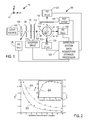
- FIG. 2 illustrates measurement results obtained with a system such as shown in FIG. 1 .
- FIG. 3 illustrates a representative system for measuring turbidity.
- FIG. 4 illustrates a representative method of measuring turbidity.
- FIG. 5 illustrates an additional representative system for measuring turbidity.
- values, procedures, or apparatus' are referred to as “lowest”, “best”, “minimum,” or the like. It will be appreciated that such descriptions are intended to indicate that a selection among many used functional alternatives can be made, and such selections need not be better, smaller, or otherwise preferable to other selections.
- minimum refers to a minimum value or to values that are within 10%, 20%, or 25% of the minimum value.
- maximum refers to a maximum value or to values that are within 10%, 20%, or 25% of the maximum value.
- beams and light fluxes are described as propagating along one or more axes. Such axes generally are based on one or more line segments so that an axis can include a number of non-collinear segments as the axis is bent or folded or otherwise responsive to mirrors, prisms, lenses, and other optical elements.
- the term “lens” is used herein to refer to a single refractive optical element (a singlet) or a compound lens that includes one or more singlets, doublets, or other compound lenses.
- beams are shaped or directed by refractive optical elements, but in other examples, reflective optical elements such as mirrors are used, or combinations of refractive and reflective elements are used.
- Such optical systems can be referred to as dioptric, catoptric, and catadioptric, respectively.
- Other types of refractive, reflective, diffractive, holographic and other optical elements can be used as may be convenient.
- a polarized light flux generally has 90% or more (usually much more) of the associated optical power in the selected state of polarization.
- Angles are generally intended to be specified with about 10 degrees, 5 degrees, 1, degree, or 0.5 degrees and axes referred to as orthogonal can have similar deviations from 90 degrees.
- a final or other polarizer is referred to as an analyzer, if convenient.
- optical radiation refers to electromagnetic radiation at wavelengths of between about 100 nm and 10 ⁇ m, and typically between about 200 nm and 2 ⁇ m. In some examples, optical radiation is referred to as one or more beams. For convenience, optical radiation is referred to as light or a light flux in some examples, but need not be at visible wavelengths.
- optical detectors (generally referred to as detectors herein) produce electrical signals corresponding to an incident light flux. Such electrical signals can be represented as voltages, currents, and as either analog or digital signals. Measurement of an optical signal generally refers to detection of at least a portion of an optical beam with a detector.
- Various light sources can be used in the disclosed methods and apparatus such as lasers, light emitting diodes, arc lamps and other lamps. In some cases, such sources produce polarized light fluxes and in such cases, additional polarizers may not be necessary to provide a polarized light flux for specimen measurement. Polarizer orientation can be adjusted by rotation. A waveplate can be used to produce an effective rotation, without rotation of the polarizer. Electrically switchable retarders or other devices such as liquid crystal, Faraday rotator, photoelastic modulator (PEM), or Pockels cells can be used, but are generally omitted from the following description.
- PEM photoelastic modulator
- a turbidity measurement system 100 includes a light source 102 that produces a light flux that is collimated or otherwise shaped by a lens 104 or other single element or multi-element refractive and/or reflective optical system and directed along an axis 106 .
- An aperture 108 is situated to provide additional beam shaping and/or attenuate unwanted light fluxes, and a polarizer 110 , such as a linear polarizer, is situated to produce a polarized light flux that is directed along the axis 106 to an optical chopper 112 and to a sample container 114 such as a cylindrical vial as shown in FIG. 1 .
- the optical chopper 112 can be placed prior to the polarizer 110 , if desired.
- a specimen 115 is situated in the sample container 114 .
- the optical chopper 112 is driven by a chopper drive 113 that generally includes a motor assembly so as to rotate the optical chopper to produce an optical modulation to the polarized light flux at a predetermined frequency.
- a portion of the polarized light flux propagates to a detector 116 that is situated on the axis 106 .
- a first scattered portion of the polarized light flux is received by a polarizer 119 , such as a linear polarizer, that is situated along an axis 118 that is at an angle of +90 degrees with respect to the axis 106 .
- the polarizer 119 can be secured to a rotational stage 121 .
- a detector 120 is also situated along the axis 118 so as to receive the first scattered light flux portion after passing through the polarizer 119 .
- a detector 124 is situated along an axis 122 that is at an angle of ⁇ 90 degrees with respect to the axis 106 so as to receive a second scattered light flux portion.
- a detector 126 is situated to receive portions of the polarized light flux returned by a sample or a surface of the sample container, such as a specularly reflected portion from a sample vial.
- the detectors 116 , 120 , 124 , 126 , the rotational stage 121 and the chopper driver 113 are coupled to a detection system 128 to permit synchronous detection of the associated light fluxes.
- Synchronous detection is convenient, but other types of optical detection can be used, such as direct detection.
- the detection system can also be arranged to produce suitable measurement outputs based on photodetector signals associated with some or all of the detectors 116 , 120 , 124 , 126 .
- the light source 102 can be a broadband light source such as a lamp, but other light sources such as lasers, laser diodes, and light emitting diodes can be used. Optical power from the light source 102 can be monitored with an additional detector, and some light sources permit direct modulation so that synchronous detection can be used even with the optical chopper 112 omitted.
- the relative placement of the polarizer 110 and the optical chopper 112 shown in FIG. 1 is one example, but the optical chopper 112 and polarizer 110 can be placed at other locations along the axis 106 , or positionally interchanged as may be convenient.
- the detectors 120 , 124 are situated along axes 118 , 122 , respectively, that are at ⁇ 90 degrees with respect to the axis 106 . Such an arrangement permits simple analysis, but other angles can be used, and angles of different magnitudes can be used for each of the detectors 120 , 124 . Typically, angles greater than 45 degrees are preferred.
- the description of FIG. 1 generally is based on linear polarization and linear polarizers, but circular or elliptical states of polarization (SOPs) can also be used.
- Sheet polarizers, dielectric beamsplitter cubes or other dielectric polarizers can be used, or birefringent crystal polarizers such as Glan-Thompson polarizers can be used.
- a right handed coordinate systems 151 is shown having a +Y-axis that extends out of the plane FIG. 1 .
- An input linear SOP can be along the +Y-axis as indicated at 107 , but other polarization directions can be used having directions specified with reference to the coordinate system 151 or other convenient coordinate system.
- the detection system 128 can include one or more lock-in amplifiers, transimpedance amplifiers or other circuitry for processing photosignals from some or all detectors.
- Data storage, processing, and control of detector bias, rotational stage positions, chopper operation (such as frequency), control of light source output and amplifier gain can also be controlled with a processor using computer-executable instructions stored in a memory such as RAM or a hard drive.
- processors can be implemented as stand-alone or dedicated processors, or provided with a general purpose computer, a laptop, a hand held device, or a tablet computer.
- the detector 116 produces a photocurrent I PD00 associated with detection of a ballistic portion of the input polarized light flux that is transmitted by the specimen 115 ; the detector 120 produces a photocurrent I PD+90 associated with detection of a polarized portion of the input polarized light flux as scattered by the specimen 115 ; the detector 124 produces a photocurrent I PD ⁇ 90 associated with detection of an unpolarized portion of the input polarized light flux as scattered by the specimen.
- a photocurrent associated with the detector 126 is noted as I PDs .
- the numerous detectors included in the system 100 of FIG. 1 permit various measurement strategies but not all are necessary.
- I PD00 , I PD+90 , I PD ⁇ 90 , and I PDs are used above to refer to photocurrents. However, this notation is used herein to refer to light flux intensities or corresponding electrical signals at or produced by detectors which can be indicated as PD 00 , PD +90 , PD ⁇ 90 , and PD s for convenience.
- a representative analytical approach to turbidity determination is provided based on a system such as that of FIG. 1 .
- This approach is representative, and similar approaches based on other SOPs can be used.
- I 0 ⁇ I PD 00 + ⁇ I PD ⁇ 90 , (1) wherein ⁇ I PD 00 represents a minimally scattered ballistic component and ⁇ I PD ⁇ 90 represents diffusely scattered components.
- I PD ⁇ 90 is the detected intensity and is captured by detector PD ⁇ 90 .
- I PD +90 is the detected intensity and is captured by PD +90 .
- I p I ⁇ ( ⁇ ⁇
- 90 ) [ 1 + P ⁇ cos ⁇ ( 2 ⁇ ⁇ ) ] ⁇
- the fraction of the detected intensity captured by PD +90 that is polarized is the degree of linear polarization (DOLP) and is given by:
- DOLP is a representative metric for input SOP decorrelation.
- Curve 202 illustrates PD 00 (non-polarized ballistic detection, based on photodetector 116 in FIG. 1 ) and curve 204 corresponds to DOLP based on polarized detection with a vertical linear (V-SOP) polarized input (based on photodetector 120 in FIG. 1 ).
- V-SOP vertical linear
- V-SOP is perpendicular to the plane of the drawing and in a direction of the +Y-axis of the right-handed coordinate system 151 as discussed above.
- Curve 206 in the embedded plot corresponds to non-polarized detection by PD ⁇ 90 (based on photodetector 124 in FIG. 1 ) and is a polynomial fit serving to highlight non-monotonic behavior.
- the results for the polarization fraction show a monotonic exponential relationship with increasing NDC concentration. It is because of this that polarimetric implementation is seen to increase the range of scatterer concentration quantification and by extension turbidity (due to the inverse relationship between turbidity and scattering mean free path). So, whereas turbidity measurement that ignores polarization detection readily saturates (this is the case for the conventional turbidity meter—see the results in Table 1), measurement based on polarimetric implementation continues to show good correlation at higher scatterer concentrations.
- the maximal verifiable turbidity measurable in this example was that for the 2.067 mg/mL concentration (784 NTUs).
- the NP side scatter detection mode was able to quantitate up to 7.233 mg/mL with individual errors ⁇ 10% for a mean quantification error of 3.91%.
- Polarization-based detection was able to quantitate up to 13.433 mg/mL with 3.38% mean quantification error.
- the NP ballistic detection mode quantitated up to 11.367 mg/mL with 11.41% mean quantification error, but individual errors varied greatly and were much higher at just under 19%.
- Polarization-based quantitation does not require determining DOLP.
- signals for the analyzer oriented at 0 and 90 degrees i.e., corresponding to max and min respectively
- a range of values associated with max/min values for one or more reference samples of known turbidity would be used for calibration so that measured max/min values for a sample could be associated with sample turbidity or concentration using a look up table or other calibration table or curve.
- the two photodiode measurements corresponding to analyzer at 0 and 90 degrees are measure simultaneously.
- the detector 124 in FIG. 1 could be provided with an analyzer having an orientation that is orthogonal to that polarizer 119 , or both could be collected with detector 120 via a partitioned analyzer or via switching received SOPs with one or more electrooptic or other devices.
- NTUs Nephelometric Turbidity Units
- Other indications in Table 1 are: not available due to turbidimeter measurement error message (NA); not calculated (NC) as either outside of a logarithmic range for NP-PD 00 or that concentration was outside the range that was modeled for NP-PD ⁇ 90; and predicted (Pred).
- a V-SOP linear polarization input with polarization analysis for detection of the min and max intensity values of side-scatter i.e., at 90° to the incident propagation direction
- scattering sample concentration i.e., turbidity
- NDC was used a specimen but other specimens as biological tissues, drinking water, foods, cosmetics, pharmaceuticals and waste water and others can be similarly evaluated.
- a measurement system 300 includes a laser 302 that directs a measurement beam to a polarizer 304 and then to a specimen chamber 306 defined in a specimen vial 308 that is situated along an axis 310 .
- the laser 302 produces an unpolarized beam or a weakly polarized beam and the polarizer 304 is oriented so as to produce one or more selected measurement beam SOPs, typically linear SOPs.
- a detector 316 is situated on an axis 318 that is perpendicular to the axis 310 and scattered portions of the measurement beam are directed to the detector 316 through a rotatable analyzer 320 .
- a stage controller 322 adjusts a rotational angle of the analyzer 320 so that the detector 316 can produce maximum and minimum electrical signals, typically at rotation angles that differ by 90 degrees.
- the maximum and minimum electrical signals are associated with a linear polarization perpendicular to the plane of FIG. 3 (shown as 330 ) and a linear polarization parallel to the plane of FIG. 3 (shown as 332 ).
- the polarizer 304 can be oriented to produce either of these polarizations, or other linear polarizations.
- FIG. 4 illustrates a representative method 400 of measuring turbidity or concentration in a sample.
- an input measurement beam SOP is selected and at 402 , a measurement beam in this SOP is directed to a sample.
- portions of the measurement beam scattered by the sample are detected for SOPs that produce maximum and minimum electrical signals.
- a turbidity or concentration estimate is produced based on these electrical signals.
- FIG. 5 illustrates a measurement apparatus 500 that includes a light source 502 that emits a light flux that is collected by a lens 504 and directed through a polarizer 506 along an axis 508 to a specimen 510 that is retained in a container 512 .
- a transmitted beam portion is directed to an electrically controllable optical retarder 525 (for example, a liquid crystal or Pockels effect device, or a rotatable retarder) that is coupled to a controller 526 that is used to select a retardation value or orientation.
- a polarizer 522 is situated to receive the transmitted beam from the retarder 522 and a detector 524 produces an electrical signal associated with the portion transmitted to the detector 524 . If desired, maximum and minimum signal values for orthogonal SOPs (in view of the retardance applied by the retarder 52 scan be obtained, and a concentration or turbidity estimate produced by a detection system 528 .
- a beam portion scattered along a perpendicular axis 530 is directed to a polarizer assembly 532 that contain polarizer segments 532 A, 532 B associated with orthogonal SOPs.
- a detector assembly 536 has detectors 536 A, 536 B that are situated to receive scattered beam portions from the polarizer segments 532 A, 532 B, respectively.
- the detection system 528 can use the electrical signals from the detectors 536 A, 536 B to produce concentration or turbidity estimates.
- the detector 536 can be a segmented detector, or two or more individual detectors can be used.
- the polarizer segments 532 A, 532 B typically are polarizers having different orientations, and fixed into a common assembly.
- a single polarizer can be used an provide with a 1 ⁇ 2 wave retarder on an input side, wherein the 1 ⁇ 2 wave retarder is oriented at 45 degrees with respect to the polarization axis of the single polarizer. In either case, measurements that are effectively at two orthogonal directions are obtained.
- a lens 540 can be used so that scattered beam portions are directed to each of the detectors 536 A, 536 B.
- polarization based measurement can use either or both of the axes 508 , 530 , or an axis or axes at angles between 0 and 180 degrees, or 0 and 90 degrees.
- the light source can be a broadband source, a source that comprises a plurality spectral lines, and spectral filters can be used to select a spectral region of interest.
Abstract
Description
I 0 =α·I PD
wherein α·IPD
α·I PD
wherein τt is an optical density corresponding to loss of the original beam intensity due to both absorption and scatter, i.e., τt=τa+τs, respectively. From Eq. (2), the diffuse component therefore consists of all the light scattered out of the original input beam that is not absorbed; this can be written as:
β1,2 ·I PD
When polarization is ignored IPD
β1 ·I PD
I t(φ)=½·{[1+P·cos(2φ)]|max+[1+P·cos(2φ)]|min}, (5)
wherein P is a degree of polarization and is an azimuthal angle of analyzer orientation with respect to the plane of incidence (i.e., an input SOP) and min and max reference the associated extrema. Note that for an unpolarized light input, in the absence of polarization effects due to scatter, P=0 and therefore It lacks a polarization component and is strictly made up of depolarized light, which does not obey Malus' Law. Likewise in the absence of an analyzer in front of a polarization insensitive detector (i.e., for PD−90),
[1+P·cos(2φ)]|max≡[1+P·cos(2φ)]|min =k, (6)
wherein k is a constant conveying the ensuing polarization insensitivity. From Eq. (4), for normalized intensity,
I t =I p +I d=1. (7)
[1+P·cos(2φ)]|max and [1+P·cos(2φ)]|min occur for φ|0 and φ|90, respectively, from Eq. (5). Therefore,
I t =I(φ|0)+I(φ|90). (8)
Rearranging Eq. (8) to directly map to Eq. (5), yields:
I t =I(φ|0)−I(φ|90)+2·I(φ|90)≡I p +I d, (9)
wherein Ip=I(φ|0)−I(φ|90) and Id=2·I(φ|90). Also, note that
However, other functions of the difference between signals associated with different SOPs in the scattered beam can be used. From Eq. (11) it is clear therefore that DOLP is a representative metric for input SOP decorrelation.
β2 ·I PD
and as sample concentration increases, τt→∞, thus leading to e−τ
β2 ·I PD
and if τa<<1, then expanding the exponential function yields, to 1st order approximation,
β2 ·I PD
Clearly, past the initial saturation point, if τa were to increase with NDC concentration due to greater scatterer agglomeration (a typical consequence of increased scatterer density), then the value of Isat would decrease also as seen in
y=a 1 ·e (−a
wherein y represents either DOLP or NP-intensity The model fit parameters are presented in Table 2 for R2=0.9984, 0.9934, and 0.9994 (polarized-DOLP and non-polarized, NP-PD00 and -PD−90 implementations respectively). Additionally, the models were used to predict the 2.067 mg/mL concentration validation sample with the following respective errors: 5.47%, 22.91%, and 8.07%.
| TABLE 1 |
| Measurement results. |
| Concentration | P (V-SOP) | NP-PD00 | NP-PD-90 |
| (mg/mL) | NTUs | Pred. | % Error | Pred. | % Error | Pred. | % Error |
| 1.033 | 383 | 1.006 | 2.63 | 1.23 | 18.81 | 1.01 | 2.29 |
| 2.067 | 784 | — | — | — | — | — | — |
| 3.100 | 1000* | 3.241 | 4.54 | 3.16 | 1.99 | 3.08 | 0.69 |
| 5.167 | NA | 4.996 | 3.30 | 4.57 | 11.47 | 5.59 | 8.27 |
| 7.233 | NA | 7.375 | 1.96 | 6.57 | 9.16 | 7.45 | 3.01 |
| 9.300 | NA | 8.986 | 3.38 | 7.59 | 18.36 | 7.80 | 16.08 |
| 11.367 | NA | 11.044 | 2.84 | 12.35 | 8.68 | NC | NC |
| 13.433 | NA | 12.757 | 5.04 | NC | NC | NC | NC |
| 15.500 | NA | 20.525 | 32.42 | NC | NC | NC | NC |
| Mean | †3.38 | 11.41 | 6.07 | ||||
| TABLE 2 |
| Model fit parameters. |
| DOLP(V-SOP) | PD00 | ‡PD−90 | |
| Coef. | Value ± σ | Value ± σ | Value ± σ |
| a1 | 0.3115 ± 0.0082 | 1.3020 ± 0.054 | −1.7830 ± 0.0424 |
| a2 | 0.2525 ± 0.0165 | 0.3732 ± 0.042 | 0.4734 ± 0.0328 |
| a3 | 0.0879 ± 0.0045 | 1.0050 ± 0.030 | 1.8030 ± 0.0311 |
Claims (11)
Priority Applications (1)
| Application Number | Priority Date | Filing Date | Title |
|---|---|---|---|
| US14/855,307 US9823183B2 (en) | 2015-09-15 | 2015-09-15 | Extending the range of turbidity measurement using polarimetry |
Applications Claiming Priority (1)
| Application Number | Priority Date | Filing Date | Title |
|---|---|---|---|
| US14/855,307 US9823183B2 (en) | 2015-09-15 | 2015-09-15 | Extending the range of turbidity measurement using polarimetry |
Publications (2)
| Publication Number | Publication Date |
|---|---|
| US20170074780A1 US20170074780A1 (en) | 2017-03-16 |
| US9823183B2 true US9823183B2 (en) | 2017-11-21 |
Family
ID=58236769
Family Applications (1)
| Application Number | Title | Priority Date | Filing Date |
|---|---|---|---|
| US14/855,307 Active 2036-01-25 US9823183B2 (en) | 2015-09-15 | 2015-09-15 | Extending the range of turbidity measurement using polarimetry |
Country Status (1)
| Country | Link |
|---|---|
| US (1) | US9823183B2 (en) |
Citations (11)
| Publication number | Priority date | Publication date | Assignee | Title |
|---|---|---|---|---|
| US4884886A (en) * | 1985-02-08 | 1989-12-05 | The United States Of America As Represented By The Department Of Energy | Biological particle identification apparatus |
| US5104221A (en) * | 1989-03-03 | 1992-04-14 | Coulter Electronics Of New England, Inc. | Particle size analysis utilizing polarization intensity differential scattering |
| US5515163A (en) * | 1994-09-01 | 1996-05-07 | Sunshine Medical Instruments, Inc. | Method and apparatus for detection, analysis and identification of particles |
| US5788632A (en) * | 1996-03-19 | 1998-08-04 | Abbott Laboratories | Apparatus and process for the non-invasive measurement of optically active compounds |
| US6118532A (en) * | 1997-03-28 | 2000-09-12 | Alv-Laser Vertriebsgesellschaft Mbh | Instrument for determining static and/or dynamic light scattering |
| US6567166B2 (en) | 2001-02-21 | 2003-05-20 | Honeywell International Inc. | Focused laser light turbidity sensor |
| US6721051B2 (en) * | 2000-09-20 | 2004-04-13 | Synergetic Technologies, Inc. | Non-intrusive method and apparatus for characterizing particles based on scattering matrix elements measurements using elliptically polarized radiation |
| US20090059227A1 (en) * | 2007-09-04 | 2009-03-05 | James Plant | Method and system for the polarmetric analysis of scattering media utilising polarization difference sensing (pds) |
| US20110181869A1 (en) * | 2008-09-26 | 2011-07-28 | Horiba, Ltd. | Particle characterization device |
| US20140043609A1 (en) | 2012-08-08 | 2014-02-13 | Ut-Battelle, Llc | Method for using polarization gating to measure a scattering sample |
| US8654319B2 (en) | 2009-01-23 | 2014-02-18 | University Of Maryland, Baltimore County | Chlorophyll and turbidity sensor system |
-
2015
- 2015-09-15 US US14/855,307 patent/US9823183B2/en active Active
Patent Citations (13)
| Publication number | Priority date | Publication date | Assignee | Title |
|---|---|---|---|---|
| US4884886A (en) * | 1985-02-08 | 1989-12-05 | The United States Of America As Represented By The Department Of Energy | Biological particle identification apparatus |
| US5104221A (en) * | 1989-03-03 | 1992-04-14 | Coulter Electronics Of New England, Inc. | Particle size analysis utilizing polarization intensity differential scattering |
| US5515163A (en) * | 1994-09-01 | 1996-05-07 | Sunshine Medical Instruments, Inc. | Method and apparatus for detection, analysis and identification of particles |
| US5788632A (en) * | 1996-03-19 | 1998-08-04 | Abbott Laboratories | Apparatus and process for the non-invasive measurement of optically active compounds |
| US6118532A (en) * | 1997-03-28 | 2000-09-12 | Alv-Laser Vertriebsgesellschaft Mbh | Instrument for determining static and/or dynamic light scattering |
| US6721051B2 (en) * | 2000-09-20 | 2004-04-13 | Synergetic Technologies, Inc. | Non-intrusive method and apparatus for characterizing particles based on scattering matrix elements measurements using elliptically polarized radiation |
| US6567166B2 (en) | 2001-02-21 | 2003-05-20 | Honeywell International Inc. | Focused laser light turbidity sensor |
| US20090059227A1 (en) * | 2007-09-04 | 2009-03-05 | James Plant | Method and system for the polarmetric analysis of scattering media utilising polarization difference sensing (pds) |
| US7956998B2 (en) | 2007-09-04 | 2011-06-07 | James Plant | Method and system for the polarmetric analysis of scattering media utilising polarization difference sensing (PDS) |
| US20110181869A1 (en) * | 2008-09-26 | 2011-07-28 | Horiba, Ltd. | Particle characterization device |
| US8625093B2 (en) * | 2008-09-26 | 2014-01-07 | Horiba, Ltd. | Particle characterization device |
| US8654319B2 (en) | 2009-01-23 | 2014-02-18 | University Of Maryland, Baltimore County | Chlorophyll and turbidity sensor system |
| US20140043609A1 (en) | 2012-08-08 | 2014-02-13 | Ut-Battelle, Llc | Method for using polarization gating to measure a scattering sample |
Non-Patent Citations (1)
| Title |
|---|
| Ghosh et al., "Mueller matrix decomposition for extraction of individual polarization parameters from complex turbid media exhibiting multiple scattering, optical activity, and linear birefringence," J. Biomed. Opt., 13:044036-1-044036-14 (Aug. 2008). |
Also Published As
| Publication number | Publication date |
|---|---|
| US20170074780A1 (en) | 2017-03-16 |
Similar Documents
| Publication | Publication Date | Title |
|---|---|---|
| JP5155325B2 (en) | Determination of surface and thickness | |
| JP3741465B2 (en) | Dual beam tunable spectrometer | |
| JP2008032548A (en) | Light scattering detection device | |
| US20100188651A1 (en) | Optical property sensor | |
| CN104089855A (en) | Method and device for measuring particles by polarized light scattering | |
| WO2005119169A3 (en) | Beam profile complex reflectance system and method for thin film and critical dimension measurements | |
| US5303024A (en) | Scintillometer for the measurment of the structure function constant and the inner scale of atmospheric refractive index fluctuations | |
| JP2004205500A (en) | Apparatus and method for measuring birefringence | |
| US20150160118A1 (en) | Method And System For Optical Measurements Of Contained Liquids Having A Free Surface | |
| CN115165758A (en) | Detection equipment and method | |
| EP1065497B1 (en) | Method of polarimetry and method of urinalysis using the same | |
| JPH0663867B2 (en) | Interfering device for wavefront condition detection | |
| CA1302700C (en) | Method and apparatus for optical distance measurement | |
| US20080123099A1 (en) | Photothermal conversion measuring instrument | |
| US7920262B2 (en) | Systems for measuring backscattered light using rotating mirror | |
| US9823183B2 (en) | Extending the range of turbidity measurement using polarimetry | |
| US9097647B2 (en) | Method for using polarization gating to measure a scattering sample | |
| US20040238361A1 (en) | Apparatus and method for measuring optically active materials | |
| US11105737B2 (en) | Spectroscopic analysis device | |
| CN208847653U (en) | Real-time polarization sensitive terahertz time-domain ellipsometer | |
| RU186572U1 (en) | TWO-WAVE POLARIZATION LIDAR | |
| RU2302623C2 (en) | Ellipsometer | |
| Luo et al. | Rotating a half-wave plate by 45°: An ideal calibration method for the gain ratio in polarization lidars | |
| JPH10281876A (en) | Polarizing imaging system | |
| RU2463568C1 (en) | Apparatus for thermal lens spectroscopy |
Legal Events
| Date | Code | Title | Description |
|---|---|---|---|
| AS | Assignment |
Owner name: UT-BATTELLE, LLC, TENNESSEE Free format text: ASSIGNMENT OF ASSIGNORS INTEREST;ASSIGNOR:BABA, JUSTIN S.;REEL/FRAME:037138/0082 Effective date: 20151116 |
|
| AS | Assignment |
Owner name: U.S. DEPARTMENT OF ENERGY, DISTRICT OF COLUMBIA Free format text: CONFIRMATORY LICENSE;ASSIGNOR:UT-BATTELLE, LLC;REEL/FRAME:037324/0844 Effective date: 20151202 |
|
| STCF | Information on status: patent grant |
Free format text: PATENTED CASE |
|
| MAFP | Maintenance fee payment |
Free format text: PAYMENT OF MAINTENANCE FEE, 4TH YR, SMALL ENTITY (ORIGINAL EVENT CODE: M2551); ENTITY STATUS OF PATENT OWNER: SMALL ENTITY Year of fee payment: 4 |