US9821784B2 - Brake apparatus - Google Patents
Brake apparatus Download PDFInfo
- Publication number
- US9821784B2 US9821784B2 US14/371,309 US201314371309A US9821784B2 US 9821784 B2 US9821784 B2 US 9821784B2 US 201314371309 A US201314371309 A US 201314371309A US 9821784 B2 US9821784 B2 US 9821784B2
- Authority
- US
- United States
- Prior art keywords
- fluid passage
- valve
- brake
- fluid
- inlet
- Prior art date
- Legal status (The legal status is an assumption and is not a legal conclusion. Google has not performed a legal analysis and makes no representation as to the accuracy of the status listed.)
- Expired - Fee Related, expires
Links
Images


Classifications
-
- B—PERFORMING OPERATIONS; TRANSPORTING
- B60—VEHICLES IN GENERAL
- B60T—VEHICLE BRAKE CONTROL SYSTEMS OR PARTS THEREOF; BRAKE CONTROL SYSTEMS OR PARTS THEREOF, IN GENERAL; ARRANGEMENT OF BRAKING ELEMENTS ON VEHICLES IN GENERAL; PORTABLE DEVICES FOR PREVENTING UNWANTED MOVEMENT OF VEHICLES; VEHICLE MODIFICATIONS TO FACILITATE COOLING OF BRAKES
- B60T11/00—Transmitting braking action from initiating means to ultimate brake actuator without power assistance or drive or where such assistance or drive is irrelevant
- B60T11/10—Transmitting braking action from initiating means to ultimate brake actuator without power assistance or drive or where such assistance or drive is irrelevant transmitting by fluid means, e.g. hydraulic
- B60T11/26—Reservoirs
-
- B—PERFORMING OPERATIONS; TRANSPORTING
- B60—VEHICLES IN GENERAL
- B60T—VEHICLE BRAKE CONTROL SYSTEMS OR PARTS THEREOF; BRAKE CONTROL SYSTEMS OR PARTS THEREOF, IN GENERAL; ARRANGEMENT OF BRAKING ELEMENTS ON VEHICLES IN GENERAL; PORTABLE DEVICES FOR PREVENTING UNWANTED MOVEMENT OF VEHICLES; VEHICLE MODIFICATIONS TO FACILITATE COOLING OF BRAKES
- B60T13/00—Transmitting braking action from initiating means to ultimate brake actuator with power assistance or drive; Brake systems incorporating such transmitting means, e.g. air-pressure brake systems
- B60T13/10—Transmitting braking action from initiating means to ultimate brake actuator with power assistance or drive; Brake systems incorporating such transmitting means, e.g. air-pressure brake systems with fluid assistance, drive, or release
- B60T13/12—Transmitting braking action from initiating means to ultimate brake actuator with power assistance or drive; Brake systems incorporating such transmitting means, e.g. air-pressure brake systems with fluid assistance, drive, or release the fluid being liquid
- B60T13/16—Transmitting braking action from initiating means to ultimate brake actuator with power assistance or drive; Brake systems incorporating such transmitting means, e.g. air-pressure brake systems with fluid assistance, drive, or release the fluid being liquid using pumps directly, i.e. without interposition of accumulators or reservoirs
- B60T13/161—Systems with master cylinder
- B60T13/165—Master cylinder integrated or hydraulically coupled with booster
- B60T13/166—Part of the system directly actuated by booster pressure
-
- B—PERFORMING OPERATIONS; TRANSPORTING
- B60—VEHICLES IN GENERAL
- B60T—VEHICLE BRAKE CONTROL SYSTEMS OR PARTS THEREOF; BRAKE CONTROL SYSTEMS OR PARTS THEREOF, IN GENERAL; ARRANGEMENT OF BRAKING ELEMENTS ON VEHICLES IN GENERAL; PORTABLE DEVICES FOR PREVENTING UNWANTED MOVEMENT OF VEHICLES; VEHICLE MODIFICATIONS TO FACILITATE COOLING OF BRAKES
- B60T13/00—Transmitting braking action from initiating means to ultimate brake actuator with power assistance or drive; Brake systems incorporating such transmitting means, e.g. air-pressure brake systems
- B60T13/10—Transmitting braking action from initiating means to ultimate brake actuator with power assistance or drive; Brake systems incorporating such transmitting means, e.g. air-pressure brake systems with fluid assistance, drive, or release
- B60T13/66—Electrical control in fluid-pressure brake systems
- B60T13/662—Electrical control in fluid-pressure brake systems characterised by specified functions of the control system components
-
- B—PERFORMING OPERATIONS; TRANSPORTING
- B60—VEHICLES IN GENERAL
- B60T—VEHICLE BRAKE CONTROL SYSTEMS OR PARTS THEREOF; BRAKE CONTROL SYSTEMS OR PARTS THEREOF, IN GENERAL; ARRANGEMENT OF BRAKING ELEMENTS ON VEHICLES IN GENERAL; PORTABLE DEVICES FOR PREVENTING UNWANTED MOVEMENT OF VEHICLES; VEHICLE MODIFICATIONS TO FACILITATE COOLING OF BRAKES
- B60T13/00—Transmitting braking action from initiating means to ultimate brake actuator with power assistance or drive; Brake systems incorporating such transmitting means, e.g. air-pressure brake systems
- B60T13/10—Transmitting braking action from initiating means to ultimate brake actuator with power assistance or drive; Brake systems incorporating such transmitting means, e.g. air-pressure brake systems with fluid assistance, drive, or release
- B60T13/66—Electrical control in fluid-pressure brake systems
- B60T13/68—Electrical control in fluid-pressure brake systems by electrically-controlled valves
- B60T13/686—Electrical control in fluid-pressure brake systems by electrically-controlled valves in hydraulic systems or parts thereof
-
- B—PERFORMING OPERATIONS; TRANSPORTING
- B60—VEHICLES IN GENERAL
- B60T—VEHICLE BRAKE CONTROL SYSTEMS OR PARTS THEREOF; BRAKE CONTROL SYSTEMS OR PARTS THEREOF, IN GENERAL; ARRANGEMENT OF BRAKING ELEMENTS ON VEHICLES IN GENERAL; PORTABLE DEVICES FOR PREVENTING UNWANTED MOVEMENT OF VEHICLES; VEHICLE MODIFICATIONS TO FACILITATE COOLING OF BRAKES
- B60T7/00—Brake-action initiating means
- B60T7/02—Brake-action initiating means for personal initiation
- B60T7/04—Brake-action initiating means for personal initiation foot actuated
- B60T7/042—Brake-action initiating means for personal initiation foot actuated by electrical means, e.g. using travel or force sensors
-
- B—PERFORMING OPERATIONS; TRANSPORTING
- B60—VEHICLES IN GENERAL
- B60T—VEHICLE BRAKE CONTROL SYSTEMS OR PARTS THEREOF; BRAKE CONTROL SYSTEMS OR PARTS THEREOF, IN GENERAL; ARRANGEMENT OF BRAKING ELEMENTS ON VEHICLES IN GENERAL; PORTABLE DEVICES FOR PREVENTING UNWANTED MOVEMENT OF VEHICLES; VEHICLE MODIFICATIONS TO FACILITATE COOLING OF BRAKES
- B60T8/00—Arrangements for adjusting wheel-braking force to meet varying vehicular or ground-surface conditions, e.g. limiting or varying distribution of braking force
- B60T8/32—Arrangements for adjusting wheel-braking force to meet varying vehicular or ground-surface conditions, e.g. limiting or varying distribution of braking force responsive to a speed condition, e.g. acceleration or deceleration
- B60T8/34—Arrangements for adjusting wheel-braking force to meet varying vehicular or ground-surface conditions, e.g. limiting or varying distribution of braking force responsive to a speed condition, e.g. acceleration or deceleration having a fluid pressure regulator responsive to a speed condition
- B60T8/343—Systems characterised by their lay-out
- B60T8/344—Hydraulic systems
- B60T8/348—4 Channel systems
-
- B—PERFORMING OPERATIONS; TRANSPORTING
- B60—VEHICLES IN GENERAL
- B60T—VEHICLE BRAKE CONTROL SYSTEMS OR PARTS THEREOF; BRAKE CONTROL SYSTEMS OR PARTS THEREOF, IN GENERAL; ARRANGEMENT OF BRAKING ELEMENTS ON VEHICLES IN GENERAL; PORTABLE DEVICES FOR PREVENTING UNWANTED MOVEMENT OF VEHICLES; VEHICLE MODIFICATIONS TO FACILITATE COOLING OF BRAKES
- B60T8/00—Arrangements for adjusting wheel-braking force to meet varying vehicular or ground-surface conditions, e.g. limiting or varying distribution of braking force
- B60T8/32—Arrangements for adjusting wheel-braking force to meet varying vehicular or ground-surface conditions, e.g. limiting or varying distribution of braking force responsive to a speed condition, e.g. acceleration or deceleration
- B60T8/34—Arrangements for adjusting wheel-braking force to meet varying vehicular or ground-surface conditions, e.g. limiting or varying distribution of braking force responsive to a speed condition, e.g. acceleration or deceleration having a fluid pressure regulator responsive to a speed condition
- B60T8/38—Arrangements for adjusting wheel-braking force to meet varying vehicular or ground-surface conditions, e.g. limiting or varying distribution of braking force responsive to a speed condition, e.g. acceleration or deceleration having a fluid pressure regulator responsive to a speed condition including valve means of the relay or driver controlled type
-
- B—PERFORMING OPERATIONS; TRANSPORTING
- B60—VEHICLES IN GENERAL
- B60T—VEHICLE BRAKE CONTROL SYSTEMS OR PARTS THEREOF; BRAKE CONTROL SYSTEMS OR PARTS THEREOF, IN GENERAL; ARRANGEMENT OF BRAKING ELEMENTS ON VEHICLES IN GENERAL; PORTABLE DEVICES FOR PREVENTING UNWANTED MOVEMENT OF VEHICLES; VEHICLE MODIFICATIONS TO FACILITATE COOLING OF BRAKES
- B60T8/00—Arrangements for adjusting wheel-braking force to meet varying vehicular or ground-surface conditions, e.g. limiting or varying distribution of braking force
- B60T8/32—Arrangements for adjusting wheel-braking force to meet varying vehicular or ground-surface conditions, e.g. limiting or varying distribution of braking force responsive to a speed condition, e.g. acceleration or deceleration
- B60T8/34—Arrangements for adjusting wheel-braking force to meet varying vehicular or ground-surface conditions, e.g. limiting or varying distribution of braking force responsive to a speed condition, e.g. acceleration or deceleration having a fluid pressure regulator responsive to a speed condition
- B60T8/48—Arrangements for adjusting wheel-braking force to meet varying vehicular or ground-surface conditions, e.g. limiting or varying distribution of braking force responsive to a speed condition, e.g. acceleration or deceleration having a fluid pressure regulator responsive to a speed condition connecting the brake actuator to an alternative or additional source of fluid pressure, e.g. traction control systems
- B60T8/4809—Traction control, stability control, using both the wheel brakes and other automatic braking systems
- B60T8/4827—Traction control, stability control, using both the wheel brakes and other automatic braking systems in hydraulic brake systems
-
- B—PERFORMING OPERATIONS; TRANSPORTING
- B60—VEHICLES IN GENERAL
- B60T—VEHICLE BRAKE CONTROL SYSTEMS OR PARTS THEREOF; BRAKE CONTROL SYSTEMS OR PARTS THEREOF, IN GENERAL; ARRANGEMENT OF BRAKING ELEMENTS ON VEHICLES IN GENERAL; PORTABLE DEVICES FOR PREVENTING UNWANTED MOVEMENT OF VEHICLES; VEHICLE MODIFICATIONS TO FACILITATE COOLING OF BRAKES
- B60T8/00—Arrangements for adjusting wheel-braking force to meet varying vehicular or ground-surface conditions, e.g. limiting or varying distribution of braking force
- B60T8/32—Arrangements for adjusting wheel-braking force to meet varying vehicular or ground-surface conditions, e.g. limiting or varying distribution of braking force responsive to a speed condition, e.g. acceleration or deceleration
- B60T8/88—Arrangements for adjusting wheel-braking force to meet varying vehicular or ground-surface conditions, e.g. limiting or varying distribution of braking force responsive to a speed condition, e.g. acceleration or deceleration with failure responsive means, i.e. means for detecting and indicating faulty operation of the speed responsive control means
- B60T8/885—Arrangements for adjusting wheel-braking force to meet varying vehicular or ground-surface conditions, e.g. limiting or varying distribution of braking force responsive to a speed condition, e.g. acceleration or deceleration with failure responsive means, i.e. means for detecting and indicating faulty operation of the speed responsive control means using electrical circuitry
-
- F—MECHANICAL ENGINEERING; LIGHTING; HEATING; WEAPONS; BLASTING
- F15—FLUID-PRESSURE ACTUATORS; HYDRAULICS OR PNEUMATICS IN GENERAL
- F15B—SYSTEMS ACTING BY MEANS OF FLUIDS IN GENERAL; FLUID-PRESSURE ACTUATORS, e.g. SERVOMOTORS; DETAILS OF FLUID-PRESSURE SYSTEMS, NOT OTHERWISE PROVIDED FOR
- F15B1/00—Installations or systems with accumulators; Supply reservoir or sump assemblies
- F15B1/26—Supply reservoir or sump assemblies
- F15B1/265—Supply reservoir or sump assemblies with pressurised main reservoir
-
- B—PERFORMING OPERATIONS; TRANSPORTING
- B60—VEHICLES IN GENERAL
- B60T—VEHICLE BRAKE CONTROL SYSTEMS OR PARTS THEREOF; BRAKE CONTROL SYSTEMS OR PARTS THEREOF, IN GENERAL; ARRANGEMENT OF BRAKING ELEMENTS ON VEHICLES IN GENERAL; PORTABLE DEVICES FOR PREVENTING UNWANTED MOVEMENT OF VEHICLES; VEHICLE MODIFICATIONS TO FACILITATE COOLING OF BRAKES
- B60T2270/00—Further aspects of brake control systems not otherwise provided for
- B60T2270/40—Failsafe aspects of brake control systems
- B60T2270/402—Back-up
Definitions
- the present invention relates to a brake apparatus.
- a brake boosting function for boosting a brake operating force of a driver is realized by feeding a brake fluid, which is pressurized by a pump after being drawn from a reservoir, to wheel cylinders.
- a brake fluid which is pressurized by a pump after being drawn from a reservoir.
- Patent Document-1 Japanese Laid-open Patent Application (Tokkai) 2007-216767
- a brake apparatus of the present invention there are provided between a reservoir tank and each wheel cylinder a normally closed pressure reducing valve and a normally closed shutoff valve which are connected in series.
- the brake apparatus of the invention can exhibit a high reliability against a failure of the apparatus.
- FIG. 1 is a block diagram of a brake apparatus of a first embodiment.
- FIG. 2 is a diagram of a master cylinder M/C and a reservoir tank RSV which are employed in the first embodiment.
- FIG. 3 is a flowchart depicting an operation flow of a wheel cylinder fluid pressure controlling process that is carried out by a control unit CU of the first embodiment in a normal condition.
- FIG. 4 is a setting map for looking up a target wheel cylinder pressure relative to a pedal stroke in the first embodiment.
- FIG. 5 is a table depicting a wheel cylinder fluid pressure controlling logic of the first embodiment in the normal condition.
- FIG. 6 is a control characteristic map plotting a valve opening degree of a hydraulic pressure control valve 34 of the first embodiment relative to a current value.
- FIG. 7 is a flowchart depicting an operation flow of a fluid pressure control selection process that is carried out by the control unit CU of the first embodiment.
- FIG. 8 is a table depicting a wheel cylinder fluid pressure controlling logic of the first embodiment in a failure condition.
- FIG. 9 is a hydraulic circuit diagram of the first embodiment showing a flow of a brake fluid in a normal condition.
- FIG. 10 is a time chart depicting operation of various valves and a motor M of the first embodiment in a normal condition.
- FIG. 11 is a hydraulic circuit diagram of the first embodiment showing a flow of the brake fluid in a failure condition.
- FIG. 12 is a time chart depicting operation of the various valves and the motor M of the first embodiment at a time when both systems are in failure.
- FIG. 13 is a time chart depicting operation of the various valves and the motor M of the first embodiment at a time when one of the systems is in failure.
- FIG. 14 is a bock diagram of a brake apparatus of a second embodiment.
- FIG. 15 is a diagram of a master cylinder M/C and a reservoir tank RSV which are employed in the second embodiment.
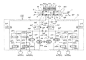
- FIG. 1 shows a brake apparatus of a first embodiment, the brake apparatus comprising a fluid pressure control unit HU and a control unit (controller) CU.
- the fluid pressure control unit HU comprises various fluid passages that are formed in a housing of aluminum and various valves and a motor M that are connected to the housing.
- the fluid pressure control unit HU has a piping construction called X-piping which comprises two systems, one being P-system (first brake piping system) and the other being S-system (second brake piping system).
- characters P and S affixed to ends of references of various portions shown in FIG. 1 indicate P-system and S-system respectively
- references FL, RR, FR and RL indicate positions of a front-left wheel, a rear-right wheel, a front-right wheel and a rear-left wheel respectively.
- attaching the characters P, S, or FL, RR, FR and RL will be omitted.
- the fluid pressure control unit HU of the first embodiment uses an open type hydraulic circuit.
- the open type hydraulic circuit is a hydraulic circuit in which a brake fluid fed to wheel cylinders W/C can be directly returned to a reservoir tank RSV without passing through the master cylinder M/C.
- a brake pedal (viz., brake actuating member) BP is connected to the master cylinder M/C through an input rod IR.
- the brake apparatus of the first embodiment is of a system that is not provided with a brake boosting device that boosts a brake operating force of a driver. Accordingly, in the fluid pressure control carried out upon a normal braking, upon detecting a manipulated variable (pedal stroke) of a brake pedal BP by a stroke sensor (brake operation condition detecting section) 1 , the brake fluid stored in the reservoir tank RSV is sucked up and pressurized by a pump P to boost the wheel cylinders W/C thereby to realize a desired boost ratio. Between the input rod IR and a piston 4 of the master cylinder M/C, there is arranged a stroke simulator 2 for absorbing the pedal stroke of the brake peal BP by a predetermined amount.
- FIG. 2 is a diagram of the master cylinder M/C and the reservoir tank RSV which are employed in the first embodiment.
- the master cylinder M/C is equipped with a cylinder body 3 , a piston 4 , a first piston seal 5 , a second piston seal 6 , a third piston seal 7 and a fourth piston seal 8 .
- the cylinder body 3 is constructed of an aluminum material and formed with first to sixth ports 6 , 10 , 11 , 12 , 13 and 14 .
- the first port (viz., first outlet port) 9 is connected to a first fluid passage 15 P of the P-system and the second port (viz., second outlet port) 10 is connected to a first fluid passage 15 S of the S-system.
- the third port 11 is connected to an inlet fluid passage 16 P of the P-system and the fourth port 12 is connected to an inlet fluid passage 16 S of the S-system.
- the fifth port 13 is connected to one 41 a of chambers of the reservoir tank RSV and the fifth port 14 is connected to the other 41 b of the chambers of the reservoir tank RSV.
- the reservoir tank RSV is integral with the master cylinder M/C and has a partition plate 40 by which the two chambers 41 a and 41 b are separated from one another.
- the piston 4 is slidably received in a cylindrical inner wall of the cylinder body 3 and connected with the brake pedal BP.
- the piston 4 comprises a primary piston 17 a and a secondary piston 17 b .
- the first piston seal 5 seals between the inner cylindrical surface of the cylinder body 3 and an outer cylindrical surface of the primary piston 17 a thereby to define a primary hydraulic chamber (viz., first fluid chamber) 18 .
- the primary hydraulic chamber 18 is connected to the first port 9 .
- the second piston seal 6 seals between the inner cylindrical surface of the cylinder body 3 and an outer cylindrical surface of the secondary piston 17 b thereby to define a secondary hydraulic chamber (viz., second fluid chamber) 19 .
- the secondary hydraulic chamber 19 is connected to the second port 19 .
- the third piston seal 7 seals between the inner cylindrical surface of the cylinder body 3 and the outer cylindrical surface of the primary piston 17 a thereby to define a first auxiliary fluid chamber 20 .
- the first auxiliary fluid chamber 20 is connected to the third and fifth ports 11 and 13 .
- the fourth piston seal 8 seals between the inner cylindrical surface of the cylinder body 3 and the outer cylindrical surface of the secondary piston 17 b thereby to define a second auxiliary fluid chamber 21 .
- the second auxiliary fluid chamber 21 is connected to the fourth and sixth ports 12 and 14 .
- the P-system there are connected the wheel cylinder W/C(FL) of the front-left wheel and the wheel cylinder W/C(RR) of the right-rear wheel
- the S-system there are connected the wheel cylinder W/C(FR) of the right-front wheel and the wheel cylinder W/C(RL) of the left-rear wheel
- the pumps PP and PS are for example plunger pumps or gear pumps, each being driven by a single motor M and functioning to pressurize a brake fluid led from an inlet portion 22 a and discharge the pressurized brake fluid to an outlet portion 22 b.
- the first fluid passage 15 connects the outlet portion 22 b of the pump P to the first port 9 or the second port 10 .
- the first fluid passage 15 is equipped with a normally open type electromagnetic gate out valve 23 that opens when deenergized and closes when energized.
- the first fluid passage 15 has a fluid passage 24 that bypasses the gate out valve 23 , and the fluid passage 24 is equipped with a check valve 25 .
- the check valve 25 allows a flowing of the brake fluid in a direction from the master cylinder M/C toward the outlet portion 22 b of the pump P and stops a flowing of the brake fluid in a reversed direction.
- the first fluid passage 15 at a portion between the outlet portion 22 b of the pump P and the gate out valve 23 is connected to the wheel cylinder W/C through a second fluid passage 26 .
- the second fluid passage 26 has branched passages for all of the wheel cylinders W/C, and each of the branched passages is equipped with a normally open type electromagnetic pressure increasing valve 27 .
- Each branched passage has a fluid passage 28 that bypasses the pressure increasing valve 27 , and the fluid passage 28 is equipped with a check valve 29 .
- the check valve 29 allows a flowing of the brake fluid in a direction from the wheel cylinder W/C toward the outlet portion 22 b of the pump P and stops a flowing of the brake fluid in a reversed direction.
- the inlet fluid passage 16 connects the third port 11 or the fourth port 12 to the inlet portion 22 a of the pump P.
- the inlet fluid passage 16 is equipped with a normally closed type electromagnetic reservoir shutting valve 31 that closes when deenergized and opens when energized.
- a position (or portion) of the inlet fluid passage 16 that is nearer to the inlet portion 22 a of the pump P than the reservoir shutting valve 31 and a position (or portion) of the second fluid passage 26 that is nearer to the wheel cylinder W/C than the pressure increasing valve 27 are connected through a pressure reduction fluid passage 32 .
- the pressure reducing fluid passage 32 is equipped with a pressure reducing valve 30 that is a normally closed electromagnetic valve. That is, the reservoir shutting valve 31 and the pressure reducing valve 30 are connected to the reservoir tank RSV and the wheel cylinder W/C in series.
- a portion of the second fluid passage 26 that extends from the pressure increasing valve 27 to a position where the passage 26 is connected to the first fluid passage 15 and a position (or portion) of the inlet fluid passage 16 that is nearer to the inlet portion 22 a of the pump P than the reservoir shutting valve 31 are connected through a third fluid passage 33 .
- the third fluid passage 33 is equipped with a hydraulic pressure control valve 34 that is a normally closed type proportional control valve.
- the first fluid passage 15 of the S-system is equipped with a first fluid pressure sensor 35 that detects a master cylinder pressure.
- a second fluid pressure sensor 36 that detects a discharge pressure of the pump P.
- a portion of the first fluid passage 15 that extends from the outlet portion 22 b of the pump P to a position where the passage 15 is connected to the second fluid passage 26 is equipped with a check valve 37 .
- the check valve 37 allows a flowing of the brake fluid in a direction from the outlet portion 22 b of the pump P toward the second fluid passage 26 and stops a flowing of the brake fluid in a reversed direction.
- the control unit CU Based on a stroke detected by the stroke sensor 1 and hydraulic pressures detected by the first and second fluid pressure sensors 35 and 36 , the control unit CU operates the gate out valve 23 , the pressure increasing valve 27 , the pressure reducing valve 30 , the reservoir shutting valve 31 and the hydraulic pressure control valve 34 for controlling the hydraulic pressure in each wheel cylinder W/C.
- FIG. 3 is a flowchart depicting an operation flow of a wheel cylinder fluid pressure controlling process that is carried out by the control unit CU of the first embodiment in a normal condition. In the following, operation steps will be described.
- step S 101 sensor values detected by the sensors are read.
- FIG. 4 is a setting map that plots a target wheel cylinder pressure relative to the pedal stroke in case of the first embodiment, in which the target wheel cylinder pressure is so set as to show a larger value as the pedal stroke increases.
- step S 103 the hydraulic pressure control valve 34 , the gate out valve 23 , the reservoir shutting valve 31 , the pressure increasing valve 27 , the pressure reducing valve 30 and the motor M are controlled based on the target wheel cylinder pressure calculated at step S 102 with reference to the logic shown in FIG. 5 .
- the control logic for each valve and the motor M will be described hereinafter.
- step S 104 judgment is carried out as to whether the wheel cylinder pressure is substantially equal to the target wheel cylinder or not. If YES, the operation flow goes to RETURN and if NO, the operation flow goes to step S 103 .
- FIG. 5 is table showing a control logic for the wheel cylinder fluid pressure in the first embodiment in a normal condition. In the following, control method for each valve and the motor M will be described for every scenes.
- the control starts from a non-controlled condition as shown in FIG. 1 (viz., hydraulic pressure control valve 34 : closed, gate out valve 23 : open, reservoir shutting valve 31 : closed, pressure increasing valve 27 : open, pressure reducing valve 30 : closed, motor: OFF) and then takes a controlled condition wherein an open degree of the hydraulic pressure control valve 34 is so controlled (viz., wheel cylinder pressure control) as to cause the pressure (viz., wheel cylinder pressure) detected by the second fluid pressure sensor 36 to indicate a target wheel cylinder pressure thereby closing the gate out valve 23 , opening the reservoir shutting valve 31 and naking the motor M ON (only in case of pressure increasing).
- FIG. 6 is a control characteristic map plotting a valve opening degree of the hydraulic pressure control valve 34 of the first embodiment relative to a current value.
- the hydraulic pressure control valve 34 functions to move in a closing direction when the current value is equal to or higher than a first predetermined value, and the opening degree of the valve becomes small as the current value increases, and when the current value becomes equal to or higher than a second predetermined value, the valve takes its full open position.
- the control starts from the condition shown in FIG. 1 and then takes a controlled condition wherein the hydraulic pressure control valve 34 is so controlled as to cause the pressure (viz., wheel cylinder pressure) detected by the second fluid pressure sensor 36 to indicate a higher one of the target wheel cylinder pressures thereby closing the gate out valve 23 , opening the reservoir shutting valve 31 and making the motor M ON.
- the hydraulic pressure control valve 34 is so controlled as to cause the pressure (viz., wheel cylinder pressure) detected by the second fluid pressure sensor 36 to indicate a higher one of the target wheel cylinder pressures thereby closing the gate out valve 23 , opening the reservoir shutting valve 31 and making the motor M ON.
- the pressure increasing valve 27 In case of holding or keeping the wheel cylinder pressure, the pressure increasing valve 27 is closed, and incase of reducing the pressure, the pressure increasing valve 27 is closed and the pressure reducing valve 30 is opened.
- FIG. 7 is a flowchart depicting an operation flow of a fluid pressure controlling selection process that is carried out by the control unit CU of the first embodiment. In the following, operation steps will be described.
- step S 201 judgment is carried out as to whether a failure occurs or not. If YES, the operation flow goes to step S 202 , and if NO, the operation flow goes to step S 203 .
- the hydraulic pressure control valve 34 , the gate out valve 23 , the reservoir shutting valve 31 , the pressure increasing valve 27 , the pressure reducing valve 30 and the motor M are controlled based on the target wheel cylinder pressure calculated at step S 102 with reference to the logic shown in FIG. 8 .
- the control logic for each valve and the motor M will be described hereinafter.
- step S 203 the wheel cylinder fluid pressure control at the time of normal condition as shown in FIG. 3 is carried out.
- FIG. 8 is a table showing a control logic for the wheel cylinder fluid pressure in the first embodiment in a failure condition. In the following, control method for each valve and the motor M will be described for every scenes.
- the other system that is, the normal side system carries out the wheel cylinder hydraulic pressure control for the normal condition, and the system in failure is controlled to close the reservoir shutting valve 31 .
- FIG. 9 is a hydraulic circuit diagram of the first embodiment showing a flow of the brake fluid in the normal condition
- FIG. 10 is a time chart depicting operation of various valves and the motor M of the first embodiment in the normal condition.
- a flow of the brake fluid at the time of increasing the pressure is indicated by arrows in S-system and a flow of the brake fluid at the time of reducing the pressure is indicated by arrows in P-system.
- the gate out valve 23 is closed thereby to shut off the fluid communication between the master cylinder M/C and each of the wheel cylinders W/C. Thereafter, the reservoir shutting valve 31 is opened and the motor M is energized. With this, the brake fluid sucked from the reservoir tank RSV is pressurized by the pump P and discharged to the second fluid passage 26 .
- the hydraulic pressure control valve 34 is controlled to vary its open degree in such a manner that the pressure detected by the second fluid pressure sensor 36 coincides with the target wheel cylinder pressure. With this, boosting to the pedal depression force by the pump-used pressure increasing is realized (see t 0 to t 1 of FIG. 10 ).
- the gate out valve 23 is closed thereby to shut off the fluid communication between the master cylinder M/C and each of the wheel cylinders W/C. Thereafter, the reservoir shutting valve 31 is opened and the hydraulic pressure control valve 34 is controlled to vary its open degree in such a manner that the pressure detected by the second fluid pressure sensor 36 coincides with the target wheel cylinder pressure. With this, unnecessary brake fluid can be returned from the inlet fluid passage 16 to the reservoir tank RSV (see t 2 to t 3 of FIG. 10 ).
- FIG. 11 is a hydraulic circuit diagram of the first embodiment showing a flow of the brake fluid in a failed condition
- FIG. 12 is a time chart depicting operation of various valves and the motor M of the first embodiment in a failed condition of both systems
- FIG. 13 is a time chart depicting operation of the various valves of a failed one of the systems and the motor M of the first embodiment in a condition wherein one of the systems is in failure.
- a flow of brake fluid at the time of increasing the pressure is indicated by arrows in S-system which is in failure and a flow of the brake fluid at the time of reducing the pressure is indicated by arrows in P-system which is in failure.
- the gate out valve 23 is opened and the reservoir shutting valve 31 is closed.
- a brake fluid pressure generated in the master cylinder M/C in accordance with the pedal depression force of the driver can be delivered to the wheel cylinders W/C through the first fluid passage 15 and the second fluid passage 26 , so that a braking force in accordance with the pedal depressing force can be produced (see t 0 to t 1 of FIG. 12 ).
- unnecessary brake fluid left in the wheel cylinders W/C due to reduction in the pedal depressing force of the driver can be returned to the master cylinder M/C through the second fluid passage 26 and the first fluid passage 15 (see t 2 to t 3 of FIG. 12 ).
- the normally operated system is able to feed a pressurized brake fluid to the wheel cylinders W/C like in the case depicted by FIG. 10 , and the failed one of the systems is able to generate a braking force in accordance with the pedal depressing force like in the case depicted by FIG. 12 .
- a normally closed valve is provided between the wheel cylinders and the reservoir, so that upon failure in electric power source, undesired phenomenon in which the brake fluid would be slovenly shifted from the wheel cylinders to the reservoir suppressing the wheel cylinders from receiving the brake fluid is avoided. That is, a so-called useless depression of the brake pedal is prevented.
- means for shutting of the fluid communication between the wheel cylinders and the reservoir is a single normally closed valve, if the normally closed valve becomes out of order and locked at its open position, the flow of the brake fluid from the master cylinder to the reservoir can not be stopped and thus reliability is low.
- the brake fluids from wheel cylinders of both piping systems are joined and led to the reservoir through a single fluid passage. Accordingly, if one of the piping systems is subjected to a leakage to the outside, the brake fluid in the normally operated piping system is forced to leak through the single fluid passage. Accordingly, in the above-mentioned apparatus, it has been impossible to permit the normally operated piping system to generate a braking force for an associated motor vehicle.
- the inlet fluid passages 16 are respectively provided for both piping systems and the reservoir tank RSV is constructed to have two chambers 41 a and 41 b with usage of the partition plate 40 , even if one of the piping systems is subjected to a leakage to the outside, a braking force can be produced by the other (viz., normally operated) piping system and thus, reliability in case of failure is much more increased.
- the master cylinder M/C is provided with the first and second auxiliary fluid chambers 20 and 21 connected to the reservoir tank RSV, and the inlet fluid passage 16 is connected to the reservoir tank RSV and the inlet portion 22 a of the pump P through the first and second auxiliary fluid chambers 20 and 21 . Accordingly, there is no need of preparing an exterior piping such as a hose or the like for providing a construction serving as the inlet fluid passage 16 , and thus, mountability is improved.
- the inlet fluid passage 16 is formed in a housing made of aluminum material and the inlet fluid passage 16 is made of a steel pipe, a piping reliability is increased as compared with a construction in which an external piping such as a hose or the like made of a flexible material is clamped and fixed to a base portion by a hose clamp.
- the brake apparatus of the first embodiment can be produced by adding the inlet fluid passage 16 and the reservoir shutting valve 31 to an existing system that includes the gate out valve 23 , the pressure increasing valve 27 , the pressure reducing valve 30 and the pump P. That is, since the brake apparatus can be produced by making a small change to an existing system, it is very advantageous in regards to cost.
- the control unit CU controls the gate out valve 23 in a valve closing direction, controls the pressure increasing valve 27 in a valve opening direction, controls the pressure reducing valve 30 in a valve closing direction and carries out a pressure increasing control for driving the pump P, and thus, a pressure increasing control for the power boosting function and the like can be realized with a simple control.
- the hydraulic pressure control valve 34 To a third fluid passage 33 that connects a portion of the second fluid passage 26 between the pressure increasing valve 27 and a position where the passage 26 is connected to the first fluid passage 15 to the inlet fluid passage 16 , there is connected the hydraulic pressure control valve 34 . Due to the hydraulic pressure control valve 34 , at the time of carrying out the pressure increasing control, unnecessary part of the brake fluid discharged from the outlet portion 22 b of the pump P can be returned to the inlet portion 22 a of the pump P. Since the hydraulic pressure control valve 34 is higher in responsibility than the pump P, controllability is improved. Due to the hydraulic pressure control valve 34 , at the time of carrying out the pressure reducing control, unnecessary part of the brake fluid can be returned from the inlet fluid passage 16 to the reservoir tank RSV. Furthermore, since the hydraulic pressure control valve 34 is a proportional control valve, a very fine controlling of the hydraulic pressure is made and thus, the controllability can be much increased.
- the hydraulic pressure control valve 34 and reservoir shutting valve 31 are controlled to move in an opening direction for returning the brake fluid in the wheel cylinders W/C to the reservoir tank RSV.
- the pressure reducing control can be carried out with a simple control.
- the pump P and the valves are controlled to carry out a hydraulic pressure control even under a failure of one of the piping systems.
- the braking force can be adjusted by using the other normal one of the piping systems.
- the brake apparatus of the first embodiment has advantages that will be described in the following.
- a system that comprises a stroke sensor 1 that detects a pedal stroke (operation condition) of a brake pedal BP actuated by a driver; a pump P that produces a hydraulic pressure for a wheel cylinder W/C based on the pedal stroke detected by the stroke sensor 1 ; a master cylinder M/C that includes first and second ports 9 and 10 connected to the wheel cylinder W/C, a tubular cylinder body 3 including primary and secondary hydraulic chambers 18 and 19 for producing a hydraulic pressure upon brake operation by the driver, a piston 4 slidably received in a cylindrical inner surface of the cylinder body 3 and linked with the brake pedal BP and first and second piston seals 5 and 6 which respectively seal between the cylindrical inner surface of the cylinder body 3 and a cylindrical outer surface of the piston 4 to define the primary and secondary hydraulic chambers 18 and 19 ; a reservoir tank RSV that is integrally mounted to the master cylinder M/C; an inlet fluid passage 16 that connects the inlet portion 22 a of the pump P to the reservoir tank RSV;
- the master cylinder M/C is equipped with first and second auxiliary fluid chambers 20 and 21 connected to the reservoir tank RSV that is hermetically isolated from the primary and secondary hydraulic chambers 18 and 19 , and the inlet fluid passage 16 passes through the first and second auxiliary fluid chambers 20 and 21 and connects the reservoir tank RSV and the inlet portion 22 a of the pump P.
- the brake apparatus is characterized by including an gate out valve 23 connected to a first fluid passage 15 that connects an outlet portion 22 b of a pump P to first and second ports 9 and 10 , a second fluid passage 26 that is branched from a passage between the outlet portion 22 b of the pump P of the first fluid passage 15 and the gate out valve 23 and connected to a wheel cylinder W/C and a pressure increasing valve 27 that is connected to the second fluid passage 26 .
- the brake apparatus of the invention can be provided by making a miner change to a known system, it is advantageous in cost.
- the brake apparatus is equipped with a control unit CU that controls the pump P and various valves, in which the control unit CU carries out a pressure increasing control to control the gate out valve 23 in a valve closing direction, the pressure increasing valve 27 in a valve opening direction and the pressure reducing valve 30 in a valve closing direction.
- a third fluid passage 33 that connects an interposition between the pressure increasing valve 27 of the second fluid passage 26 and a junction portion between the second fluid passage 26 and the first fluid passage 15 to the inlet fluid passage 16 , and the third fluid passage 33 is provided with a hydraulic pressure control valve 34 .
- FIG. 14 is a block diagram of a brake apparatus of a second embodiment
- FIG. 15 is a diagram of a master cylinder M/C and a reservoir tank RSV which are employed in the second embodiment.
- a point in which the inlet fluid passage 16 is connected to the reservoir tank RSV is different from that in the first embodiment.
- a portion from the reservoir tank RSV to the reservoir shutting valve 31 is made of a rubber hose.
- first and second pipe portions 42 a and 42 b At side surfaces of the reservoir tank RSV, there are provided two, namely, first and second pipe portions 42 a and 42 b .
- An inner end of the first pipe portion 42 a is connected to one 41 a of the chambers, and an inner end of the second pipe portion 42 b is connected to the other 41 b of the chambers.
- the inlet fluid passages 16 P and 16 S are clamped and fixed to outer surfaces of the first and second pipe portions 42 a and 42 b through hose clamps.
- the master cylinder M/C of the second embodiment has such a construction as that of the first embodiment with deletion of the third to sixth ports 11 , 12 , 13 and 14 .
- the inlet fluid passages 16 are clamped and fixed to the reservoir tank RSV by the clamps, assembling work is simple as compared with that of the first embodiment, and thus, it is advantageous in regards to cost.
- the stroke sensor 1 is used as a brake operation condition detecting section and a target wheel cylinder pressure is set based on the pedal stroke.
- a leg-power sensor for detecting a pedal depressing force is used as the brake operation condition detecting section, and the target wheel cylinder pressure is set based on the pedal depressing force.
- a brake apparatus as defined in claim 5 which is characterized in that the hydraulic pressure control valve is a proportional valve.
- a brake apparatus as defined in claim 2 which is characterized in that the inlet fluid passage is made of a steel tube.
- a brake apparatus comprising a brake piping that includes a first brake piping system and a second brake piping system isolated from the first brake piping system, each piping system having a plurality of wheel cylinders that are mounted to respective road wheels for producing a braking force;
- a brake operation condition detecting section that detects an operation condition of a brake operation member actuated by a driver
- a pump provided to each of the piping systems and producing a hydraulic pressure for the wheel cylinders based on the brake operation condition detected by the brake operation condition detecting section;
- a cylinder body including a first fluid chamber that has a first outlet port connected to the first brake piping system and produces a hydraulic pressure upon braking operation by the driver and a second fluid chamber that has a second outlet port connected to the second brake piping system and produces a hydraulic pressure upon braking operation of the driver, the second fluid chamber being isolated from the first fluid chamber;
- a master cylinder including a plurality of pistons that are slidably received in a cylindrical inner surface of the cylinder body and connected to the brake operation member, a first piston seal that seals between the cylindrical inner surface of the cylinder body and a cylindrical outer surface of one of the pistons thereby to define the first fluid chamber and a second piston seal that seals between the cylindrical inner surface of the cylinder body and a cylindrical outer surface of the other of the pistons thereby to define the second fluid chamber;
- a reservoir tank that is integral with the master cylinder
- a first inlet fluid passage that connects an inlet portion of the pump of the first brake piping system to the reservoir tank;
- a second inlet fluid passage that connects an inlet portion of the pump of the second brake piping system to the reservoir tank;
- first and second pressure reducing fluid passages that connect the first and second inlet fluid passages to the wheel cylinders respectively;
- a normally closed pressure reducing valve provided to each of the pressure reducing fluid passages, the normally closed pressure reducing valve being opened when it is intended to depressurize the brake fluid in the wheel cylinders thereby to return the brake fluid to the reservoir tank through the corresponding inlet fluid passage,
- each of the inlet fluid passages is provided with a normally closed shutting valve that is connected to the pressure reducing valve in series with respect to the wheel cylinder and the reservoir tank.
- a braking force for the vehicle can be adjusted by using the normally operated piping system.
- a pressure increasing valve connected to the second fluid passage.
- the brake apparatus can be produced by making a small change to an existing system, it is advantageous in regards to cost.
- a pressure increasing valve connected to the second fluid passage.
- the brake apparatus an be produced by making a small change to an existing system, it is advantageous in regards to cost.
- the pressure increasing control can be carried out with a simple control.
- a brake apparatus comprising a master cylinder that is equipped with a cylinder body that includes a first fluid chamber that has an outlet port connected to a wheel cylinder and produces a hydraulic pressure upon braking operation by a driver, a piston that is slidably received in a cylindrical inner surface of the cylinder body and connected to a brake operating member and a first piston seal that seals between the cylindrical inner surface of the cylinder body and a cylindrical outer surface of the piston thereby to define the first fluid chamber;
- a brake apparatus which is characterized in that the inlet fluid passage is constructed of a steel pipe.
Landscapes
- Engineering & Computer Science (AREA)
- Mechanical Engineering (AREA)
- Transportation (AREA)
- Physics & Mathematics (AREA)
- Fluid Mechanics (AREA)
- General Engineering & Computer Science (AREA)
- Regulating Braking Force (AREA)
- Valves And Accessory Devices For Braking Systems (AREA)
Abstract
Description
Claims (17)
Applications Claiming Priority (3)
| Application Number | Priority Date | Filing Date | Title |
|---|---|---|---|
| JP2012026079A JP5848980B2 (en) | 2012-02-09 | 2012-02-09 | Brake device |
| JP2012-026079 | 2012-02-09 | ||
| PCT/JP2013/052184 WO2013118632A1 (en) | 2012-02-09 | 2013-01-31 | Brake apparatus |
Publications (2)
| Publication Number | Publication Date |
|---|---|
| US20150007559A1 US20150007559A1 (en) | 2015-01-08 |
| US9821784B2 true US9821784B2 (en) | 2017-11-21 |
Family
ID=48947396
Family Applications (1)
| Application Number | Title | Priority Date | Filing Date |
|---|---|---|---|
| US14/371,309 Expired - Fee Related US9821784B2 (en) | 2012-02-09 | 2013-01-31 | Brake apparatus |
Country Status (5)
| Country | Link |
|---|---|
| US (1) | US9821784B2 (en) |
| JP (1) | JP5848980B2 (en) |
| CN (1) | CN104105625A (en) |
| DE (1) | DE112013000910T5 (en) |
| WO (1) | WO2013118632A1 (en) |
Cited By (5)
| Publication number | Priority date | Publication date | Assignee | Title |
|---|---|---|---|---|
| TWI719513B (en) * | 2018-06-26 | 2021-02-21 | 日商富士金股份有限公司 | Flow control method and flow control device |
| US20210347219A1 (en) * | 2017-03-21 | 2021-11-11 | Arctic Cat Inc. | Off-road utility vehicle |
| US20220135012A1 (en) * | 2020-10-30 | 2022-05-05 | Hyundai Mobis Co., Ltd. | Integrated braking device for vehicle and braking method therefor |
| US11926365B2 (en) | 2017-03-21 | 2024-03-12 | Arctic Cat Inc. | Cab and fasteners for vehicle cab |
| US12240319B2 (en) | 2017-03-21 | 2025-03-04 | Arctic Cat Inc. | Off-road utility vehicle |
Families Citing this family (6)
| Publication number | Priority date | Publication date | Assignee | Title |
|---|---|---|---|---|
| JP5841455B2 (en) * | 2012-02-24 | 2016-01-13 | 日立オートモティブシステムズ株式会社 | Brake device |
| JP6063824B2 (en) * | 2013-06-21 | 2017-01-18 | 日立オートモティブシステムズ株式会社 | Brake control device |
| JP2017077810A (en) * | 2015-10-21 | 2017-04-27 | 日立オートモティブシステムズ株式会社 | Brake control device |
| KR102507730B1 (en) * | 2020-11-03 | 2023-03-07 | 현대모비스 주식회사 | Hydraulic Block for Electronic Brake System for Vehicle |
| JP7697804B2 (en) * | 2021-03-26 | 2025-06-24 | 株式会社Subaru | Brake system |
| CN114537357A (en) * | 2022-03-07 | 2022-05-27 | 北京英创汇智科技有限公司 | Dual-winding wire-controlled redundant braking system for unmanned automobile |
Citations (16)
| Publication number | Priority date | Publication date | Assignee | Title |
|---|---|---|---|---|
| US4026319A (en) * | 1974-12-21 | 1977-05-31 | Girling Limited | Hydraulic reservoirs for vehicle braking systems |
| JPS63215454A (en) | 1987-02-19 | 1988-09-07 | アルフレツド・テヴエス・ゲーエムベーハー | hydraulic brake system |
| JPH02201208A (en) | 1989-01-31 | 1990-08-09 | Toshiba Corp | Defect inspector |
| JPH10244916A (en) | 1997-03-06 | 1998-09-14 | Toyota Motor Corp | Braking force controller |
| JP2001063553A (en) | 1999-06-21 | 2001-03-13 | Daihatsu Motor Co Ltd | Electronically controlled brake system |
| US6290306B1 (en) * | 1996-09-26 | 2001-09-18 | Robert Bosch Gmbh | Hydraulic brake system for a vehicle |
| US20040212245A1 (en) | 2003-04-24 | 2004-10-28 | Nissan Motor Co., Ltd. | Vehicle brake system |
| JP2004345629A (en) | 2003-04-28 | 2004-12-09 | Nissan Motor Co Ltd | Brake fluid pressure control circuit |
| JP2007216767A (en) | 2006-02-15 | 2007-08-30 | Advics:Kk | Vehicular brake control device |
| US20080234909A1 (en) * | 2007-03-19 | 2008-09-25 | Hitachi, Ltd. | Brake control apparatus and pump-up system |
| JP2008265450A (en) | 2007-04-18 | 2008-11-06 | Nissan Motor Co Ltd | Brake device for vehicle |
| US20090072615A1 (en) * | 2007-09-14 | 2009-03-19 | Hitachi, Ltd. | Apparatus for and method of controlling brakes |
| US20090226298A1 (en) * | 2008-03-10 | 2009-09-10 | Hitachi, Ltd. | Tandem pump |
| US20100244553A1 (en) * | 2009-03-24 | 2010-09-30 | Hitachi Automotive Systems, Ltd. | Automotive Hydraulic Brake System |
| US9050949B2 (en) * | 2009-11-20 | 2015-06-09 | Toyota Jidosha Kabushiki Kaisha | Braking apparatus |
| US9242626B2 (en) * | 2012-02-24 | 2016-01-26 | Hitachi Automotive Systems, Ltd | Brake device |
-
2012
- 2012-02-09 JP JP2012026079A patent/JP5848980B2/en not_active Expired - Fee Related
-
2013
- 2013-01-31 US US14/371,309 patent/US9821784B2/en not_active Expired - Fee Related
- 2013-01-31 CN CN201380008766.8A patent/CN104105625A/en active Pending
- 2013-01-31 WO PCT/JP2013/052184 patent/WO2013118632A1/en not_active Ceased
- 2013-01-31 DE DE112013000910.2T patent/DE112013000910T5/en not_active Withdrawn
Patent Citations (16)
| Publication number | Priority date | Publication date | Assignee | Title |
|---|---|---|---|---|
| US4026319A (en) * | 1974-12-21 | 1977-05-31 | Girling Limited | Hydraulic reservoirs for vehicle braking systems |
| JPS63215454A (en) | 1987-02-19 | 1988-09-07 | アルフレツド・テヴエス・ゲーエムベーハー | hydraulic brake system |
| JPH02201208A (en) | 1989-01-31 | 1990-08-09 | Toshiba Corp | Defect inspector |
| US6290306B1 (en) * | 1996-09-26 | 2001-09-18 | Robert Bosch Gmbh | Hydraulic brake system for a vehicle |
| JPH10244916A (en) | 1997-03-06 | 1998-09-14 | Toyota Motor Corp | Braking force controller |
| JP2001063553A (en) | 1999-06-21 | 2001-03-13 | Daihatsu Motor Co Ltd | Electronically controlled brake system |
| US20040212245A1 (en) | 2003-04-24 | 2004-10-28 | Nissan Motor Co., Ltd. | Vehicle brake system |
| JP2004345629A (en) | 2003-04-28 | 2004-12-09 | Nissan Motor Co Ltd | Brake fluid pressure control circuit |
| JP2007216767A (en) | 2006-02-15 | 2007-08-30 | Advics:Kk | Vehicular brake control device |
| US20080234909A1 (en) * | 2007-03-19 | 2008-09-25 | Hitachi, Ltd. | Brake control apparatus and pump-up system |
| JP2008265450A (en) | 2007-04-18 | 2008-11-06 | Nissan Motor Co Ltd | Brake device for vehicle |
| US20090072615A1 (en) * | 2007-09-14 | 2009-03-19 | Hitachi, Ltd. | Apparatus for and method of controlling brakes |
| US20090226298A1 (en) * | 2008-03-10 | 2009-09-10 | Hitachi, Ltd. | Tandem pump |
| US20100244553A1 (en) * | 2009-03-24 | 2010-09-30 | Hitachi Automotive Systems, Ltd. | Automotive Hydraulic Brake System |
| US9050949B2 (en) * | 2009-11-20 | 2015-06-09 | Toyota Jidosha Kabushiki Kaisha | Braking apparatus |
| US9242626B2 (en) * | 2012-02-24 | 2016-01-26 | Hitachi Automotive Systems, Ltd | Brake device |
Cited By (7)
| Publication number | Priority date | Publication date | Assignee | Title |
|---|---|---|---|---|
| US20210347219A1 (en) * | 2017-03-21 | 2021-11-11 | Arctic Cat Inc. | Off-road utility vehicle |
| US11926365B2 (en) | 2017-03-21 | 2024-03-12 | Arctic Cat Inc. | Cab and fasteners for vehicle cab |
| US12240319B2 (en) | 2017-03-21 | 2025-03-04 | Arctic Cat Inc. | Off-road utility vehicle |
| US12409691B2 (en) | 2017-03-21 | 2025-09-09 | Arctic Cat Inc. | Off-road utility vehicle |
| TWI719513B (en) * | 2018-06-26 | 2021-02-21 | 日商富士金股份有限公司 | Flow control method and flow control device |
| US20220135012A1 (en) * | 2020-10-30 | 2022-05-05 | Hyundai Mobis Co., Ltd. | Integrated braking device for vehicle and braking method therefor |
| US11958452B2 (en) * | 2020-10-30 | 2024-04-16 | Hyundai Mobis Co., Ltd. | Integrated braking device for vehicle and braking method therefor |
Also Published As
| Publication number | Publication date |
|---|---|
| JP2013163398A (en) | 2013-08-22 |
| DE112013000910T5 (en) | 2014-11-06 |
| US20150007559A1 (en) | 2015-01-08 |
| CN104105625A (en) | 2014-10-15 |
| WO2013118632A1 (en) | 2013-08-15 |
| JP5848980B2 (en) | 2016-01-27 |
Similar Documents
| Publication | Publication Date | Title |
|---|---|---|
| US9821784B2 (en) | Brake apparatus | |
| US9522668B2 (en) | Brake apparatus | |
| US20150035353A1 (en) | Method for operating a brake system and a brake system | |
| US8052227B2 (en) | Brake apparatus for vehicle | |
| US8657388B2 (en) | Brake system for motor vehicles | |
| WO2018003539A1 (en) | Brake device and method for detecting fluid leakage in brake device | |
| KR20200118176A (en) | Electro-hydraulic vehicle power brake system for autonomous vehicles | |
| CN103338988B (en) | The brake system of vehicle and the method for making the brake system of vehicle run | |
| US9683584B2 (en) | Brake device for vehicle | |
| JP2015123932A (en) | Brake hydraulic pressure generator | |
| JP6756440B2 (en) | Hydraulic control and braking system | |
| CN101460345B (en) | Hydraulic vehicle brake system having a service brake which can be actuated by muscle force and having a device for regulating the wheel slip | |
| US9102310B2 (en) | Hydraulic unit | |
| US5558413A (en) | Brake-pressure control device having rear-axle brake circuit self-priming recirculation pump | |
| US20180370509A1 (en) | Brake Apparatus, Brake System, and Method for Controlling Brake Apparatus | |
| US10449941B2 (en) | Braking device for vehicle | |
| CN102501841B (en) | For actuation unit and the method for operation thereof of hydraulic brake system | |
| JP7093276B2 (en) | Brake control device | |
| US12291177B2 (en) | Method for testing a function in a hydraulic vehicle power brake system | |
| WO2019230547A1 (en) | Brake control device and method for detecting malfunction in brake control device | |
| JP2014169040A (en) | Brake control device | |
| US9108606B2 (en) | Fluidically controlled pressure switching valve for a vehicle brake system and vehicle brake system | |
| JP2015058718A (en) | Brake system | |
| JPH0639649U (en) | Vehicle hydraulic brake control device | |
| JPH0715471U (en) | Vehicle hydraulic brake control device |
Legal Events
| Date | Code | Title | Description |
|---|---|---|---|
| AS | Assignment |
Owner name: HITACHI AUTOMOTIVE SYSTEMS, LTD., JAPAN Free format text: ASSIGNMENT OF ASSIGNORS INTEREST;ASSIGNOR:OOSAWA, TOSHIYA;REEL/FRAME:033295/0974 Effective date: 20140422 |
|
| STCF | Information on status: patent grant |
Free format text: PATENTED CASE |
|
| AS | Assignment |
Owner name: HITACHI ASTEMO, LTD., JAPAN Free format text: CHANGE OF NAME;ASSIGNOR:HITACHI AUTOMOTIVE SYSTEMS, LTD.;REEL/FRAME:056299/0447 Effective date: 20210101 |
|
| MAFP | Maintenance fee payment |
Free format text: PAYMENT OF MAINTENANCE FEE, 4TH YEAR, LARGE ENTITY (ORIGINAL EVENT CODE: M1551); ENTITY STATUS OF PATENT OWNER: LARGE ENTITY Year of fee payment: 4 |
|
| FEPP | Fee payment procedure |
Free format text: MAINTENANCE FEE REMINDER MAILED (ORIGINAL EVENT CODE: REM.); ENTITY STATUS OF PATENT OWNER: LARGE ENTITY |
|
| LAPS | Lapse for failure to pay maintenance fees |
Free format text: PATENT EXPIRED FOR FAILURE TO PAY MAINTENANCE FEES (ORIGINAL EVENT CODE: EXP.); ENTITY STATUS OF PATENT OWNER: LARGE ENTITY |
|
| STCH | Information on status: patent discontinuation |
Free format text: PATENT EXPIRED DUE TO NONPAYMENT OF MAINTENANCE FEES UNDER 37 CFR 1.362 |
|
| FP | Lapsed due to failure to pay maintenance fee |
Effective date: 20251121 |