US9818186B2 - Method for forming 3D maxillofacial model by automatically segmenting medical image, automatic image segmentation and model formation server performing the same, and storage medium storing the same - Google Patents
Method for forming 3D maxillofacial model by automatically segmenting medical image, automatic image segmentation and model formation server performing the same, and storage medium storing the same Download PDFInfo
- Publication number
- US9818186B2 US9818186B2 US15/264,311 US201615264311A US9818186B2 US 9818186 B2 US9818186 B2 US 9818186B2 US 201615264311 A US201615264311 A US 201615264311A US 9818186 B2 US9818186 B2 US 9818186B2
- Authority
- US
- United States
- Prior art keywords
- model
- face
- region
- mandible
- segmentation
- Prior art date
- Legal status (The legal status is an assumption and is not a legal conclusion. Google has not performed a legal analysis and makes no representation as to the accuracy of the status listed.)
- Expired - Fee Related
Links
Images


Classifications
-
- G—PHYSICS
- G06—COMPUTING OR CALCULATING; COUNTING
- G06T—IMAGE DATA PROCESSING OR GENERATION, IN GENERAL
- G06T7/00—Image analysis
- G06T7/0002—Inspection of images, e.g. flaw detection
- G06T7/0012—Biomedical image inspection
-
- G—PHYSICS
- G06—COMPUTING OR CALCULATING; COUNTING
- G06T—IMAGE DATA PROCESSING OR GENERATION, IN GENERAL
- G06T17/00—Three-dimensional [3D] modelling for computer graphics
- G06T17/10—Constructive solid geometry [CSG] using solid primitives, e.g. cylinders, cubes
-
- G—PHYSICS
- G06—COMPUTING OR CALCULATING; COUNTING
- G06T—IMAGE DATA PROCESSING OR GENERATION, IN GENERAL
- G06T7/00—Image analysis
- G06T7/10—Segmentation; Edge detection
- G06T7/11—Region-based segmentation
-
- G—PHYSICS
- G06—COMPUTING OR CALCULATING; COUNTING
- G06T—IMAGE DATA PROCESSING OR GENERATION, IN GENERAL
- G06T7/00—Image analysis
- G06T7/10—Segmentation; Edge detection
- G06T7/136—Segmentation; Edge detection involving thresholding
-
- G—PHYSICS
- G06—COMPUTING OR CALCULATING; COUNTING
- G06T—IMAGE DATA PROCESSING OR GENERATION, IN GENERAL
- G06T7/00—Image analysis
- G06T7/10—Segmentation; Edge detection
- G06T7/149—Segmentation; Edge detection involving deformable models, e.g. active contour models
-
- G—PHYSICS
- G06—COMPUTING OR CALCULATING; COUNTING
- G06T—IMAGE DATA PROCESSING OR GENERATION, IN GENERAL
- G06T2207/00—Indexing scheme for image analysis or image enhancement
- G06T2207/10—Image acquisition modality
- G06T2207/10004—Still image; Photographic image
-
- G—PHYSICS
- G06—COMPUTING OR CALCULATING; COUNTING
- G06T—IMAGE DATA PROCESSING OR GENERATION, IN GENERAL
- G06T2207/00—Indexing scheme for image analysis or image enhancement
- G06T2207/10—Image acquisition modality
- G06T2207/10072—Tomographic images
- G06T2207/10081—Computed x-ray tomography [CT]
-
- G—PHYSICS
- G06—COMPUTING OR CALCULATING; COUNTING
- G06T—IMAGE DATA PROCESSING OR GENERATION, IN GENERAL
- G06T2207/00—Indexing scheme for image analysis or image enhancement
- G06T2207/20—Special algorithmic details
- G06T2207/20112—Image segmentation details
- G06T2207/20161—Level set
-
- G—PHYSICS
- G06—COMPUTING OR CALCULATING; COUNTING
- G06T—IMAGE DATA PROCESSING OR GENERATION, IN GENERAL
- G06T2207/00—Indexing scheme for image analysis or image enhancement
- G06T2207/30—Subject of image; Context of image processing
- G06T2207/30004—Biomedical image processing
- G06T2207/30008—Bone
-
- G—PHYSICS
- G06—COMPUTING OR CALCULATING; COUNTING
- G06T—IMAGE DATA PROCESSING OR GENERATION, IN GENERAL
- G06T2207/00—Indexing scheme for image analysis or image enhancement
- G06T2207/30—Subject of image; Context of image processing
- G06T2207/30196—Human being; Person
- G06T2207/30201—Face
-
- G—PHYSICS
- G06—COMPUTING OR CALCULATING; COUNTING
- G06T—IMAGE DATA PROCESSING OR GENERATION, IN GENERAL
- G06T2210/00—Indexing scheme for image generation or computer graphics
- G06T2210/41—Medical
Definitions
- the present invention relates to a technology for forming a three-dimensional (3D) model of skin and mandible by automatic image segmentation, and more particularly, to a method for forming a 3D maxillofacial model by automatic medical image segmentation, which may rapidly and efficiently form a 3D model of skin and mandible by combining a macroscopic 3D multi-segmentation technique and 2D detailed segmentation technique, an automatic image segmentation and model formation server performing the same, and a storage medium storing the same.
- the mandible is a bone that is mainly used to chew food and an important portion to hold the contours of the face.
- orthognathic surgery is carried out for mainly cosmetic purposes, and mandibular fracture surgery due to trauma and mandibular resection due to cancer are carried out.
- reconstructive surgery other than a cosmetic purpose, when a surgery to replace the mandible using the fibula of a patient is carried out, soft tissue removal and ostectomy are carried out together with several departments such as dentistry, otolaryngology, surgery, and the like, and the reconstructive surgery is one of surgeries with a high level of difficulty which takes more than 10 hours.
- 3D virtual surgical planning techniques As a method for increasing the success rate of such a surgery with the high level of difficulty and reducing the operation time, three-dimensional (3D) virtual surgical planning techniques have been recently tried.
- a doctor directly performs a manual image segmentation work for modeling a human body part that is required during a surgery, and therefore a period of about a week or more to plan the surgery has been spent and such a manual modeling results in a decrease in interobserver agreement.
- an object and a background are separated from the 2D medical images, the 2D images from which the background is separated are stacked, and then the outlines of the stacked images are connected to each other to form a 3D shape model whose inside is empty, and the 3D shape model whose volume is filled with triangular pyramid-shaped tetrahedron elements is finally generated by adjusting the accuracy of the 3D shape model, so that the 3D shape model is generated only through a process of separating the background and the object, and therefore a difference between an actual structure of the object and the generated 3D shape model may occur. In this case, it may be unsuitable to establish a surgical plan, and therefore the above-described problem still exists.
- the present invention is directed to a method for forming a three-dimensional (3D) maxillofacial model by automatic medical image segmentation, which may automatically segment the skin and mandible of a patient by combining a multi-segmentation method and a detailed segmentation method using a level set function and generate a 3D model, and thereby may help to establish more accurate and efficient surgical plan and obtain a uniform mandibular model of the patient, an automatic image segmentation and model formation server performing the same, and a storage medium storing the same.
- 3D three-dimensional
- the present invention is also directed to a method for forming a 3D maxillofacial model by automatic medical image segmentation, which may be performed at a high speed while overcoming difficulties in the segmentation due to irregularities in boundaries caused by high and low contrasts, an automatic image segmentation and model formation server performing the same, and a storage medium storing the same.
- a method for forming a three-dimensional (3D) model of skin and mandible by automatic medical image segmentation which is performed in an automatic image segmentation and model formation server, including: (a) receiving 3D medical image data that is a set of two-dimensional (2D) images for horizontal planes of a face; (b) obtaining a contrast histogram based on distribution of contrasts of the 3D medical image data, and segmenting the 3D medical image data for the face into multiple regions separated into at least one partial region based on the contrast histogram; (c) extracting only the face by removing portions other than the face from the multiple regions for the face, and extracting a skin region of the face; (d) extracting the mandible from each of the 2D images for the horizontal planes of the face through a 2D detailed segmentation technique using an active contour method based on a level set function; and (e) reconstructing the extracted skin region and mandible as the 3D model.
- the (b) obtaining of the contrast histogram may include dividing a range of the contrast into predetermined levels, and calculating the number of pixels having the contrast corresponding to each of the levels from the 3D medical image data for the face to thereby obtain the contrast histogram.
- the (b) obtaining of the contrast histogram may further include extracting, from the contrast histogram, a partial region having a peak satisfying a specific criterion using an AGMC (adaptive global maximum clustering) technique.
- AGMC adaptive global maximum clustering
- the (b) obtaining of the contrast histogram may further include segmenting the 3D medical image data into the multiple regions based on an average value of the contrast histogram of the partial region.
- the (c) extracting of only the face and the skin region thereof may include obtaining a face candidate region by binarizing the multiple regions according to label values of the multiple regions.
- the (c) extracting of only the face and the skin region thereof may further include eroding the face candidate region using a circular structural element having a radius value set based on a size of the face candidate region or a preset radius value.
- the (c) extracting of only the face and the skin region thereof may further include restricting an erosion region reaching from a center of the face candidate region to positions laterally away from each other by a preset length.
- the (c) extracting of only the face and the skin region thereof may further include extracting a connection component having a common portion with the erosion region, and expanding the erosion region using the circular structural element.
- the (d) extracting of the mandible may include selecting a sample image from the 2D images, and extracting the mandible from the sample image that is a segmentation result for the sample image
- the (d) extracting of the mandible may further include setting an initial contour of an image next to or prior to the sample image based on a contour for a segmentation result of the sample image.
- the (d) extracting of the mandible may further include emphasizing a contrast of the mandible based on contrast information about the mandible inside the initial contour.
- the (d) extracting of the mandible may further include stopping movement of the contour when the initial contour moves and reaches a boundary of the mandible.
- the (d) extracting of the mandible may further include the contour moving based on an average value of local contrasts of the inside and outside of the contour and a curvature of the contour.
- the (e) reconstructing of the extracted skin region and mandible may include reconstructing the extracted skin region and mandible as the 3D model using a surface rendering algorithm, and processing a surface of the 3D model using an HC-Laplacian algorithm
- the 3D medical image data may be CBCT (cone beam computed tomography) image data.
- the segmented multiple regions may be labeled according to contrasts of the multiple regions.
- an automatic image segmentation and model formation server which performs a method for forming a 3D maxillofacial model by automatic medical image segmentation, including: an image data reception unit that receives 3D medical image data that is a set of 2D images for horizontal planes of a face; a multi-region segmentation unit that obtains a contrast histogram based on distribution of contrasts of the 3D medical image data, and segments the 3D medical image data for the face into multiple regions separated into at least one partial region based on the contrast histogram; a purpose region segmentation unit that includes a skin detailed segmentation module for extracting only the face by removing portions other than the face from the multiple regions for the face and extracting a skin region of the face, and a mandible detailed segmentation module for extracting the mandible from each of the 2D images for the horizontal planes of the face through a 2D detailed segmentation technique using an active contour method based on a level set function; and a 3D reconstruction unit that reconstructs
- the multi-region segmentation unit may obtain the contrast histogram about the 3D medical image data, and segment the 3D medical image data into the multiple regions based on an average value of the contrast histogram of a partial region having a peak satisfying a specific criterion in the contrast histogram.
- the skin detailed segmentation module may obtain a face candidate region from the multiple regions, erode the face candidate region using a circular structural element based on a size of the face candidate region, restrict an erosion region based on a length of the face candidate region, extract a connection component having a common portion with the erosion region, and expand the erosion region using the circular structural element.
- the mandible detailed segmentation module may segment in detail an image next to or prior to a sample image based on a contour for a segmentation result of the sample image among the 2D images to thereby extract the mandible.
- a recording medium that records a program for executing a method for forming a 3D maxillofacial model by the above-described automatic medical image segmentation.
- the method for forming the 3D maxillofacial model by automatic medical image segmentation according to the present invention may be implemented by a computer-readable code on a computer-readable recording medium.
- the computer-readable recording medium includes all of recording devices that store computer-readable data.
- the computer-readable recording medium may be a ROM, a RAM, a CD-ROM, a magnetic tape, a hard disk, a floppy disk, a mobile storage device, a non-volatile memory (flash memory), an optical data storage device, and the like.
- FIG. 1 is a block diagram illustrating an automatic image segmentation and model formation server according to an embodiment of the present invention
- FIG. 2 is a flowchart illustrating a method for forming a three-dimensional (3D) model by automatic medical image segmentation, which is performed in the automatic image segmentation and model formation server of FIG. 1 ;
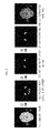
- FIGS. 3A-3C is an example of 3D medical image data
- FIGS. 4A-4B is an example of a contrast histogram
- FIGS. 5A-5B is an example of results of multi-region segmentation
- FIG. 6 is an example of a skin detailed segmentation process
- FIGS. 7A-7E is an example of an erosion and expansion operation
- FIG. 8 is an example of a process of extracting a mandible from a sample image
- FIG. 9 is an example of initial contour setting
- FIG. 10 is an example of two-dimensional (2D) detailed segmentation using a level set function
- FIG. 11 is an example of segmentation by an active contour
- FIG. 12 is a diagram illustrating a relationship between a contour and a level set function
- FIG. 13 is a diagram illustrating a phase change of a level set method
- FIG. 14 is an example of a target simultaneously having clear boundaries and blurry boundaries
- FIG. 15 is an example of a process of acquiring a contrast-enhancing image of a target
- FIGS. 16A-16B is an example of an edge indicator function
- FIG. 17 is an example of a detailed segmentation process using a level set function
- FIG. 18 is an example of 3D model reconstruction and smoothing results
- FIG. 19 is a diagram illustrating comparison between 2D images of a conventional segmentation method and a segmentation method according to an embodiment of the present invention.
- FIG. 20 is a diagram illustrating comparison between 3D models of a conventional segmentation method and a segmentation method according to an embodiment of the present invention.
- first, second, etc. may be used herein to describe various elements, components, and/or sections, these elements, components, and/or sections should not be limited by these terms. These terms are only used to distinguish one element, component, or section from another element, component, or section. Thus, a first element, component, or section discussed below could be termed a second element, component, or section without departing from the teachings of the present invention.
- references characters for example, a, b, c, etc.
- steps are used for convenience of description, and are not intended to describe the sequence of the steps.
- the steps may occur in different sequences, as long as a specific sequence is not specifically described in the context. That is, the steps may occur in a specified sequence, may occur simultaneously, or may be performed in the reverse sequence.
- FIG. 1 is a block diagram illustrating an automatic image segmentation and model formation server according to an embodiment of the present invention.
- an automatic image segmentation and model formation server 100 includes an image data reception unit 110 , a multi-region segmentation unit 120 , a purpose region segmentation unit 130 , a three-dimensional (3D) reconstruction unit 140 , and a control unit 150 , and the purpose region segmentation unit 130 includes a skin detailed segmentation module 131 and a mandible detailed segmentation module 132 .
- the image data reception unit 110 receives 3D medial image data that is a set of two-dimensional (2D) images.
- the image data reception unit 110 may receive a 3D CBCT (cone beam computed tomography) image, and for example, referring to FIGS. 3A-3C , the image data reception unit 110 may receive CBCT images for 3 A a horizontal plane image, 3 B a coronal plane image, and 3 C a sagittal plane image.
- 3D CBCT cone beam computed tomography
- the multi-region segmentation unit 120 obtains a contrast histogram for the contrast of the 3D medical image data, and segments the 3D medical image data into multiple regions based on the contrast histogram.
- the multi-region segmentation unit 120 divides a range of the contrast into 256 levels as shown in FIG. 4A , and calculates the number of pixels having the contrast corresponding to each level from the 3D medical image data, and thereby obtains the contrast histogram.
- the multi-region segmentation unit 120 extracts, from the contrast histogram, a partial region having a peak satisfying a specific criterion, that is, a meaningful peak using an AGMC (adaptive global maximum clustering) technique.
- AGMC adaptive global maximum clustering
- the multi-region segmentation unit 120 may segment the 3D medical image data into multiple regions based on an average value of the contrast histogram of each partial region, and referring to FIG. 5 , the 3D medical image data segmented into the multiple regions as shown in FIG. 5B may be obtained from an original image that is FIG. 5A through the multi-region segmentation unit 120 .
- the skin detailed segmentation module of the purpose region segmentation unit 130 extracts a skin region by morphologically processing the multiple regions.
- a skin detailed segmentation process using a morphological technique which is performed in the purpose region segmentation unit 130 will be described with reference to FIG. 6 .
- a given region may be labeled and a face candidate region may be obtained by binarizing the given region on the basis of a label value, as shown in (b) of FIG. 6 .
- the given regions as the multi-segmentation results may be labeled as values of 1, 2, 3, and 4, and regions having a label value of 3 or larger may be all binarized into a white color, and the remaining regions may be all binarized into a black color.
- an erosion image as shown in (c) of FIG. 6 may be obtained by eroding an image using a circular structural element.
- a tool which is used when measuring the corresponding image as well as the actual facial region may be also observed as a white thin strip shape on the both sides from the erosion image, so that the erosion image may be obtained using the circular structural element having a radius value set based on the size of the face candidate region or a preset radius value in order to remove the white thin stripe shape.
- other shapes other than the circular shape may be possible as the shape of the structural element. Through this, there is an effect capable of removing unnecessary elements thinly connected to the face.
- an image of a restricted erosion region as shown in (e) of FIG. 6 may be obtained by applying a region restriction method as shown in (d) of FIG. 6 .
- the region restriction method may be applied according to the position or distribution of the face candidate region in the corresponding image and a region restriction value may be set. For example, as shown in (d) of FIG.
- the face candidate region is distributed in the center of the image, and therefore an erosion region is restricted from the center of an X-axis of the image up to a place separated away in both directions by 1 ⁇ 4 (a region restriction value) of the total width of the image so that the restricted erosion region may be obtained as shown in (e) of FIG. 6 .
- the actual facial region may be obtained by extracting only connection components having a common portion with the restricted erosion region from the erosion image. That is, the actual facial region as shown in (f) of FIG. 6 is obtained by extracting only connection components having a common portion with (e) of FIG. 6 from (c) of FIG. 6 . From (f) of FIG. 6 , it can be seen that only the facial region from which a tool which is used when measuring the corresponding image and appears on the left and right sides of (c) of FIG. 6 is removed is extracted.
- the extracted facial region may have a reduced shape compared to a face surface of an original image since it is obtained from the erosion image eroded in step ⁇ circle around (2) ⁇ , so that in order to restore this, an expansion operation may be performed using the same structural element used in step ⁇ circle around (2) ⁇ , and then the inside of the erosion image may be filled to extract only the face surface as shown in (g) of FIG. 6 .
- an extracted skin may be obtained as shown in (h) of FIG. 6 by applying Gaussian smoothing to (g) of FIG. 6 .
- the center of the structural element When the center of the structural element is positioned in the boundary of the original image along the boundary of the original image, it may be classified into the erosion operation and the expansion operation according to the following cases.
- the size of the original image may be restored while regions smaller than the corresponding structural element are removed, as shown from FIG. 7A to FIG. 7E .
- the mandible detailed segmentation module 132 of the purpose region segmentation unit 130 automatically extracts the mandible through a two-dimensional (2D) detailed segmentation technique using an active contour method based on a level set function with respect to each of 2D images.
- regions having a label value of 4 or larger are selected from a labeling image of the sample image (see (b) of FIG. 8 ).
- regions having a label value of 4 or larger are selected from a labeling image of the sample image (see (b) of FIG. 8 ).
- regions having a label value of 4 or larger are selected from a labeling image of the sample image.
- regions having a label value of 4 or larger are selected from a labeling image of the sample image (see (b) of FIG. 8 ).
- an upper portion of a center portion of a y-axis of the corresponding image is selected (
- FIG. 9 is an example of initial contour setting, and in FIG. 9 , a red line indicates a segmentation result of a previous image and a blue line indicates an initial contour of a current image and has a distance difference by C with the segmentation result of the previous image.
- step (ii) detailed segmentation has been performed in a direction of an increase in a value of k
- step (iii) detailed segmentation is performed in a direction of a reduction of the value of k to obtain each mandibular image by performing the process of step (ii).
- the 2D detailed segmentation technique is a useful method in a case in which a target within an image simultaneously has clear boundaries and blurry boundaries due to co-existence of bright and dark contrasts.
- This is a method (see FIG. 11 ) which makes an initial contour stop when the initial contour reaches the boundary of the target by moving the initial contour, as an active contour based-segmentation method.
- a level set method is used so as to make it free in phase changes of the initial contour and a target contour, and in the level set method, the movement of the corresponding contour is described through a level set function by introducing a higher-level function (level set function) capable of representing the corresponding contour as 0-level set (see FIG. 12 ).
- the level set method has an advantage capable of describing various phases from a single level set function.
- Equation 1 becomes a signed distance function.
- a final level set function that represents the boundary of the target as 0-level may be obtained by deforming the level set function using a defined force in order to segment such an initial level set function.
- the purpose of detailed segmentation using the level set function in the present invention is to properly find blurry boundaries as well as clear boundaries when the target simultaneously has clear boundaries and blurry boundaries as shown in FIG. 14 .
- the level set function is deformed along an approximated delta function ⁇ ⁇ which has a value close to 1 as it is closer to the contour and has a value close to 0 as it moves away from the contour while having a value other than 0 only in the vicinity of ⁇ - of the contour (0-level of the level set function).
- F( ⁇ (X)) denotes a force for deforming ⁇ for segmentation, and will be specified later.
- the detailed segmentation technique may be developed through the following two steps: (1) contrast emphasized image of the target and (2) equation for movement of contour.
- the initial contour of the current image may be set to include contrast information of the target while it is positioned in the vicinity of the target. This assists in the improvement of a segmentation speed and an efficient segmentation process.
- a function for calculating an averaging contrast of a given image in a region having a positive function value is defined as below.
- H(•) denotes a Heaviside function which has 1 with respect to a positive variable and has 0 with respect to a negative variable.
- J ( X ) G ⁇ I *exp( ⁇ r ( I ( X ) ⁇ M ) 2 ), G ⁇ I :Gaussian kernel, ⁇ J ,r ⁇ 0 [Equation 4]
- This function has a value close to 1 when a contrast of a single pixel has a value approximated to M indicating the contrast of the target, and has a value close to 0 when the contrast of the single pixel has a value that is not approximated to M.
- M indicates the contrast of the target
- J may be an image that emphasizes the contrast of the target. Accordingly, a relationship between the initial contour and the contrast of the target is roughly divided into three cases as below, and then Equation 3 is used.
- M indicates the contrast of the target.
- Equation 5 represents a local force that is defined using a difference between an averaging contrast of the inside and outside of the contour which has been locally calculated in the vicinity of the pixel for the emphasized image and a contrast of the pixel itself.
- K h denotes an averaging kernel having a kernel size of 2h+1, and determines a degree of local calculation.
- a function H ⁇ uses an integrand of the approximated delta function used in Equation 2 as an approximated version of a Heaviside function.
- H ⁇ ⁇ ( ⁇ ⁇ ( X ) ) ⁇ 1 2 ⁇ ( 1 + ⁇ ⁇ ( X ) ⁇ + 1 ⁇ ⁇ sin ⁇ ( ⁇ ⁇ ( X ) ⁇ ) ) if ⁇ ⁇ ⁇ ⁇ ⁇ ( X ) ⁇ ⁇ ⁇ 1 if ⁇ ⁇ ⁇ ⁇ ( X ) ⁇ ⁇ 0 if ⁇ ⁇ ⁇ ⁇ ( X ) ⁇ - ⁇ .
- Equation 6 is an equation that represents a curvature of the corresponding contour and serves to keep an irregular shape of the contour more flat, thereby helping to prevent the deviation of the contour from desired boundaries.
- a function g is a function that depends on an original image I, and defined as follows:
- the function g Since the function g has a value close to 0 on edges and has a value close to 1 in smooth regions other than the edges, it is called an edge indicator function (see FIG. 16A and FIG. 16B ).
- the edge indicator function g has a large value only in the smooth regions, and therefore it is possible to prevent the contour from stopping in the undesired regions by inducing the movement of the contour in the smooth regions.
- Equation 7 denotes a local force that prevailingly exerts so as to evolve the level set function through a contrast comparison between the inside and outside of the contour which has been locally calculated, a second term ⁇ F r ( ⁇ ) thereof serves to make the contour flat, and a third term ⁇ g(I(X)) thereof is introduced to prevent a stopping phenomenon of the contour due to the local force that becomes significantly small in the smooth regions.
- ⁇ ⁇ ( ⁇ (X)) helps to carefully investigate the blurry boundaries by limiting a change region of the level set to the vicinity of ⁇ - of 0-level.
- the 3D reconstruction unit 140 reconstructs the skin region and mandible extracted by the purpose region segmentation unit 130 as a 3D model.
- a 0-level iso-surface of this data may be reconstructed as the 3D model of the mandible using a marching cube algorithm.
- the surface is subjected to smoothing treatment using the HC-Laplacian algorithm (see FIG. 18 ).
- FIGS. 19 and 20 show the superiority of the present invention compared to the conventional method.
- the conventional method has the result obtained through a variety of post-processing after initial segmentation through iso-value adjustment using the Mimics software, and such a method has difficulties when a target having irregular boundaries is segmented.
- the iso-value may be adjusted to be low in order to extract the blurry boundary, so that outer peripheral portions of the boundary of a desired target as well as even unnecessary portions around the blurry boundaries are likely to be extracted.
- the method proposed in the present invention may find only the boundary of the target in an appropriate position.
- the control unit 150 controls operations of the image data reception unit 110 , the multi-region segmentation unit 120 , the purpose region segmentation unit 130 , and the 3D reconstruction unit 140 , and controls the flow of data thereof.
- FIG. 2 is a flowchart illustrating a method for forming a 3D maxillofacial model by automatic medical image segmentation, which is performed in the automatic image segmentation and model formation server of FIG. 1 .
- the image data reception unit 110 receives 3D medical image data that is a set of 2D images.
- the 3D medical image data may be a CBCT image.
- the multi-region segmentation unit 120 obtains the contrast histogram for a contrast of the 3D medical image data, and segments the 3D medical image data into multiple regions based on the contrast histogram.
- the multiple regions may be labeled according to the contrast. More specifically, the multi-region segmentation unit 120 divides a range of the contrast into 256 levels, and calculates the number of pixels having the contrast corresponding to each level from the 3D medical image data, and thereby obtains the contrast histogram.
- a partial region having a peak satisfying a specific criterion is extracted using an AGMC (adaptive global maximum clustering) technique from the contrast histogram, and the 3D medical image data is segmented into the multiple regions based on an average value of the contrast histogram of the partial region.
- AGMC adaptive global maximum clustering
- the skin detailed segmentation module 131 of the purpose region segmentation unit 130 extracts a skin region by morphologically processing the multiple regions. More specifically, the skin detailed segmentation module 131 obtains a face candidate region by binarizing the multiple regions according to label values of the multiple regions, and erodes the face candidate region using a circular structural element having a radius value set based on a size of the face candidate region or a preset radius value. Next, the skin detailed segmentation module 131 restricts the eroded region of the face candidate region, extracts a connection component having a common portion with the eroded region, and then expands the eroded region again using the circular structural element.
- the mandible detailed segmentation module 132 of the purpose region segmentation unit 130 automatically extracts the mandible through a 2D detailed segmentation technique using a level set function-based active contour method with respect to each of 2D images. More specifically, the mandible detailed segmentation module 132 extracts a segmentation result for a sample image among the 2D images, and extracts all of segmentation results for the remaining images using the segmentation result for the sample image. The segmentation result for each image is extracted through a process of setting the initial contour, emphasizing the contrast, and moving the contour.
- the skin and mandible of a patient may be automatically segmented and a 3D model may be generated by combining a multi-segmentation method and a detailed segmentation method using a level set function, thereby helping to establish more accurate and efficient surgical plan and obtain a uniform mandibular model of the patient.
- a 3D model may be generated by combining a multi-segmentation method and a detailed segmentation method using a level set function, thereby helping to establish more accurate and efficient surgical plan and obtain a uniform mandibular model of the patient.
- the method according to the present invention may be performed at a high speed while overcoming difficulties in the segmentation due to irregularities in the boundaries caused by high and low contrasts.
- the mandible portion may be segmented by cross-sections in 2D medical images, and then, the segmentation results, that is, mandibular images extracted from each of the 2D medical images may be stacked to form a 3D model, thereby obtaining a more accurate 3D model of the mandible.
Landscapes
- Engineering & Computer Science (AREA)
- Physics & Mathematics (AREA)
- General Physics & Mathematics (AREA)
- Theoretical Computer Science (AREA)
- Computer Vision & Pattern Recognition (AREA)
- Geometry (AREA)
- Software Systems (AREA)
- Health & Medical Sciences (AREA)
- Computer Graphics (AREA)
- General Health & Medical Sciences (AREA)
- Medical Informatics (AREA)
- Life Sciences & Earth Sciences (AREA)
- Nuclear Medicine, Radiotherapy & Molecular Imaging (AREA)
- Radiology & Medical Imaging (AREA)
- Quality & Reliability (AREA)
- Apparatus For Radiation Diagnosis (AREA)
- Molecular Biology (AREA)
- Biophysics (AREA)
- Pathology (AREA)
- Biomedical Technology (AREA)
- Heart & Thoracic Surgery (AREA)
- Surgery (AREA)
- Animal Behavior & Ethology (AREA)
- Public Health (AREA)
- Veterinary Medicine (AREA)
- Image Analysis (AREA)
- Oral & Maxillofacial Surgery (AREA)
- Dentistry (AREA)
Abstract
Description
- [Patent Document 1] Korea Patent Publication No. 10-2006-0028044
J(X)=G σ
M=m(φ0)
M=m(I−m(φ0))
M=m(−I+m(φ0))
Claims (21)
Applications Claiming Priority (2)
| Application Number | Priority Date | Filing Date | Title |
|---|---|---|---|
| KR10-2015-0132843 | 2015-09-21 | ||
| KR1020150132843A KR101718868B1 (en) | 2015-09-21 | 2015-09-21 | Method for forming 3d mazillofacial model by automatically segmenting medical image, automatic image segmentation and model formation server performing the same, and storage mdeium storing the same |
Publications (2)
| Publication Number | Publication Date |
|---|---|
| US20170084026A1 US20170084026A1 (en) | 2017-03-23 |
| US9818186B2 true US9818186B2 (en) | 2017-11-14 |
Family
ID=58282712
Family Applications (1)
| Application Number | Title | Priority Date | Filing Date |
|---|---|---|---|
| US15/264,311 Expired - Fee Related US9818186B2 (en) | 2015-09-21 | 2016-09-13 | Method for forming 3D maxillofacial model by automatically segmenting medical image, automatic image segmentation and model formation server performing the same, and storage medium storing the same |
Country Status (2)
| Country | Link |
|---|---|
| US (1) | US9818186B2 (en) |
| KR (1) | KR101718868B1 (en) |
Cited By (4)
| Publication number | Priority date | Publication date | Assignee | Title |
|---|---|---|---|---|
| US11842484B2 (en) | 2021-01-04 | 2023-12-12 | James R. Glidewell Dental Ceramics, Inc. | Teeth segmentation using neural networks |
| US12136208B2 (en) | 2021-03-31 | 2024-11-05 | James R. Glidewell Dental Ceramics, Inc. | Automatic clean up of jaw scans |
| US12210802B2 (en) | 2021-04-30 | 2025-01-28 | James R. Glidewell Dental Ceramics, Inc. | Neural network margin proposal |
| US12295806B2 (en) | 2022-01-10 | 2025-05-13 | James R. Glidewell Dental Ceramics, Inc. | Automatic determination of trim-line for aligners |
Families Citing this family (15)
| Publication number | Priority date | Publication date | Assignee | Title |
|---|---|---|---|---|
| EP3297515B1 (en) * | 2015-05-17 | 2020-07-01 | Endochoice, Inc. | Endoscopic image enhancement using contrast limited adaptive histogram equalization (clahe) implemented in a processor |
| SG10201706752XA (en) * | 2017-08-17 | 2019-03-28 | Iko Pte Ltd | Systems and methods for analyzing cutaneous conditions |
| KR101953629B1 (en) | 2017-11-21 | 2019-03-05 | 서울여자대학교 산학협력단 | Method and apparatus for automatic segmentation of the mandible using shape-constrained information in cranio-maxillo-facial cbct images |
| EP3803788B1 (en) * | 2018-05-29 | 2022-07-27 | Medicim NV | Methods, systems, and computer programs for segmenting a tooth's pulp region from an image |
| CN110490851B (en) * | 2019-02-15 | 2021-05-11 | 腾讯科技(深圳)有限公司 | Mammary gland image segmentation method, device and system based on artificial intelligence |
| KR102227439B1 (en) * | 2019-03-21 | 2021-03-15 | 울산대학교 산학협력단 | Method and apparatus for analyzing facial area image |
| KR102277021B1 (en) * | 2019-08-13 | 2021-07-14 | 주식회사 디오 | Method and apparatus for separating maxilla and mandible of 3-d oral ct image |
| FI3806034T3 (en) * | 2019-10-07 | 2025-11-14 | Univ Nihon | SEGMENTATION DEVICE |
| CN113744384B (en) * | 2020-05-29 | 2023-11-28 | 北京达佳互联信息技术有限公司 | Three-dimensional face reconstruction method, device, electronic equipment and storage medium |
| CN114445320B (en) * | 2020-11-02 | 2025-07-25 | 千寻位置网络有限公司 | Image segmentation quality evaluation method and device, electronic equipment and storage medium |
| KR102330981B1 (en) * | 2020-12-30 | 2021-12-02 | 이마고웍스 주식회사 | Method of automatic segmentation of maxillofacial bone in ct image using deep learning |
| CN113129418B (en) * | 2021-03-02 | 2023-06-27 | 武汉联影智融医疗科技有限公司 | Target surface reconstruction method, device, equipment and medium based on three-dimensional image |
| CN113920128B (en) * | 2021-09-01 | 2023-02-21 | 北京长木谷医疗科技有限公司 | Method and device for segmenting femur and tibia of knee joint |
| CN115082585B (en) * | 2022-06-21 | 2025-10-03 | 北京银河方圆科技有限公司 | Medical image reconstruction methods |
| CN115294264A (en) * | 2022-06-28 | 2022-11-04 | 上海昕健医疗技术有限公司 | Orthopedic operation guide plate design method |
Citations (4)
| Publication number | Priority date | Publication date | Assignee | Title |
|---|---|---|---|---|
| KR20060028044A (en) | 2004-09-24 | 2006-03-29 | 유용석 | 3D finite element modeling method and recording medium using 2D medical image |
| US20120063655A1 (en) * | 1999-08-11 | 2012-03-15 | Case Western Reserve University | Methods and systems for producing an implant |
| US20140003695A1 (en) * | 1999-08-11 | 2014-01-02 | Case Western Reserve University | Methods and systems for producing an implant |
| US20170018088A1 (en) * | 2015-07-14 | 2017-01-19 | Samsung Electronics Co., Ltd. | Three dimensional content generating apparatus and three dimensional content generating method thereof |
-
2015
- 2015-09-21 KR KR1020150132843A patent/KR101718868B1/en not_active Expired - Fee Related
-
2016
- 2016-09-13 US US15/264,311 patent/US9818186B2/en not_active Expired - Fee Related
Patent Citations (4)
| Publication number | Priority date | Publication date | Assignee | Title |
|---|---|---|---|---|
| US20120063655A1 (en) * | 1999-08-11 | 2012-03-15 | Case Western Reserve University | Methods and systems for producing an implant |
| US20140003695A1 (en) * | 1999-08-11 | 2014-01-02 | Case Western Reserve University | Methods and systems for producing an implant |
| KR20060028044A (en) | 2004-09-24 | 2006-03-29 | 유용석 | 3D finite element modeling method and recording medium using 2D medical image |
| US20170018088A1 (en) * | 2015-07-14 | 2017-01-19 | Samsung Electronics Co., Ltd. | Three dimensional content generating apparatus and three dimensional content generating method thereof |
Cited By (5)
| Publication number | Priority date | Publication date | Assignee | Title |
|---|---|---|---|---|
| US11842484B2 (en) | 2021-01-04 | 2023-12-12 | James R. Glidewell Dental Ceramics, Inc. | Teeth segmentation using neural networks |
| US12236594B2 (en) | 2021-01-04 | 2025-02-25 | James R. Glidewell Dental Ceramics, Inc. | Teeth segmentation using neural networks |
| US12136208B2 (en) | 2021-03-31 | 2024-11-05 | James R. Glidewell Dental Ceramics, Inc. | Automatic clean up of jaw scans |
| US12210802B2 (en) | 2021-04-30 | 2025-01-28 | James R. Glidewell Dental Ceramics, Inc. | Neural network margin proposal |
| US12295806B2 (en) | 2022-01-10 | 2025-05-13 | James R. Glidewell Dental Ceramics, Inc. | Automatic determination of trim-line for aligners |
Also Published As
| Publication number | Publication date |
|---|---|
| US20170084026A1 (en) | 2017-03-23 |
| KR101718868B1 (en) | 2017-03-22 |
Similar Documents
| Publication | Publication Date | Title |
|---|---|---|
| US9818186B2 (en) | Method for forming 3D maxillofacial model by automatically segmenting medical image, automatic image segmentation and model formation server performing the same, and storage medium storing the same | |
| EP3545499B1 (en) | System and method for real-time rendering of complex data | |
| US9659364B2 (en) | Probabilistic refinement of model-based segmentation | |
| US8750585B2 (en) | Method and system for segmenting a liver object in an image | |
| JP6539303B2 (en) | Transforming 3D objects to segment objects in 3D medical images | |
| CN108038862B (en) | Interactive medical image intelligent segmentation modeling method | |
| CN107292312B (en) | Tumor CT image processing method | |
| JP2020513869A (en) | How to restore a skull | |
| CN105488849A (en) | Hybrid level set based three-dimensional tooth modeling method | |
| CN106163404A (en) | Lung for ray image is split and bone suppression technology | |
| US20150317790A1 (en) | Systems and methods for semi-automated segmentation of medical images | |
| KR101953629B1 (en) | Method and apparatus for automatic segmentation of the mandible using shape-constrained information in cranio-maxillo-facial cbct images | |
| Bischoff et al. | Isosurface reconstruction with topology control | |
| Heo et al. | Segmentation of tooth in CT images for the 3D reconstruction of teeth | |
| JP2004521425A (en) | Image processing method for evaluating the suitability of a three-dimensional mesh model mapped on a target three-dimensional surface | |
| CN109754469B (en) | Method and system for surface mesh cutting and cutting boundary optimization | |
| CN111724389B (en) | Hip joint CT image segmentation method, device, storage medium and computer equipment | |
| WO2017062453A1 (en) | Image segmentation of organs depicted in computed tomography images | |
| KR101685821B1 (en) | Method and System for Body and ROI Segmentation for Chest X-ray Images | |
| Jimenez-Carretero et al. | Optimal multiresolution 3D level-set method for liver segmentation incorporating local curvature constraints | |
| US10621726B2 (en) | Segmentation of objects in image data using channel detection | |
| Nysjö | BoneSplit-a 3D texture painting tool for interactive bone separation in CT images | |
| Abdolali et al. | Mandibular canal segmentation using 3D Active Appearance Models and shape context registration | |
| Ben-Dan et al. | Liver Tumor segmentation in CT images using probabilistic methods | |
| Salah et al. | Live-wire revisited |
Legal Events
| Date | Code | Title | Description |
|---|---|---|---|
| AS | Assignment |
Owner name: KOREA INSTITUTE OF SCIENCE AND TECHNOLOGY, KOREA, Free format text: ASSIGNMENT OF ASSIGNORS INTEREST;ASSIGNORS:KIM, SUN HEE;KIM, YOUNG JUN;KIM, LAE HYUN;AND OTHERS;REEL/FRAME:039722/0149 Effective date: 20160902 |
|
| STCF | Information on status: patent grant |
Free format text: PATENTED CASE |
|
| MAFP | Maintenance fee payment |
Free format text: PAYMENT OF MAINTENANCE FEE, 4TH YR, SMALL ENTITY (ORIGINAL EVENT CODE: M2551); ENTITY STATUS OF PATENT OWNER: SMALL ENTITY Year of fee payment: 4 |
|
| FEPP | Fee payment procedure |
Free format text: MAINTENANCE FEE REMINDER MAILED (ORIGINAL EVENT CODE: REM.); ENTITY STATUS OF PATENT OWNER: SMALL ENTITY |
|
| LAPS | Lapse for failure to pay maintenance fees |
Free format text: PATENT EXPIRED FOR FAILURE TO PAY MAINTENANCE FEES (ORIGINAL EVENT CODE: EXP.); ENTITY STATUS OF PATENT OWNER: SMALL ENTITY |
|
| STCH | Information on status: patent discontinuation |
Free format text: PATENT EXPIRED DUE TO NONPAYMENT OF MAINTENANCE FEES UNDER 37 CFR 1.362 |
|
| FP | Lapsed due to failure to pay maintenance fee |
Effective date: 20251114 |