KR101718868B1 - Method for forming 3d mazillofacial model by automatically segmenting medical image, automatic image segmentation and model formation server performing the same, and storage mdeium storing the same - Google Patents
Method for forming 3d mazillofacial model by automatically segmenting medical image, automatic image segmentation and model formation server performing the same, and storage mdeium storing the same Download PDFInfo
- Publication number
- KR101718868B1 KR101718868B1 KR1020150132843A KR20150132843A KR101718868B1 KR 101718868 B1 KR101718868 B1 KR 101718868B1 KR 1020150132843 A KR1020150132843 A KR 1020150132843A KR 20150132843 A KR20150132843 A KR 20150132843A KR 101718868 B1 KR101718868 B1 KR 101718868B1
- Authority
- KR
- South Korea
- Prior art keywords
- face
- dimensional
- region
- mandible
- image data
- Prior art date
Links
- 238000000034 method Methods 0.000 title claims abstract description 108
- 238000003709 image segmentation Methods 0.000 title claims description 30
- 230000015572 biosynthetic process Effects 0.000 title 1
- 230000036961 partial effect Effects 0.000 claims abstract description 14
- 210000004373 mandible Anatomy 0.000 claims description 54
- 230000003628 erosive effect Effects 0.000 claims description 22
- 238000004422 calculation algorithm Methods 0.000 claims description 8
- 238000007408 cone-beam computed tomography Methods 0.000 claims description 6
- 239000000284 extract Substances 0.000 claims description 6
- 238000009877 rendering Methods 0.000 claims description 3
- 238000012545 processing Methods 0.000 claims description 2
- 238000004590 computer program Methods 0.000 claims 1
- 230000006870 function Effects 0.000 description 43
- 230000001815 facial effect Effects 0.000 description 9
- 230000011218 segmentation Effects 0.000 description 8
- 238000009499 grossing Methods 0.000 description 7
- 238000001356 surgical procedure Methods 0.000 description 6
- 238000004364 calculation method Methods 0.000 description 4
- 238000010586 diagram Methods 0.000 description 4
- 238000000638 solvent extraction Methods 0.000 description 4
- 230000003044 adaptive effect Effects 0.000 description 3
- 210000000988 bone and bone Anatomy 0.000 description 3
- 238000000605 extraction Methods 0.000 description 3
- 238000007792 addition Methods 0.000 description 2
- 230000000694 effects Effects 0.000 description 2
- 230000001788 irregular Effects 0.000 description 2
- 230000000670 limiting effect Effects 0.000 description 2
- 238000005259 measurement Methods 0.000 description 2
- 230000000877 morphologic effect Effects 0.000 description 2
- 238000012935 Averaging Methods 0.000 description 1
- 208000006153 Mandibular Fractures Diseases 0.000 description 1
- 206010028980 Neoplasm Diseases 0.000 description 1
- 238000013459 approach Methods 0.000 description 1
- 201000011510 cancer Diseases 0.000 description 1
- 230000001055 chewing effect Effects 0.000 description 1
- 239000003086 colorant Substances 0.000 description 1
- 238000005094 computer simulation Methods 0.000 description 1
- 238000007796 conventional method Methods 0.000 description 1
- 239000002537 cosmetic Substances 0.000 description 1
- 238000002316 cosmetic surgery Methods 0.000 description 1
- 238000013500 data storage Methods 0.000 description 1
- 230000003247 decreasing effect Effects 0.000 description 1
- 230000001419 dependent effect Effects 0.000 description 1
- 210000002082 fibula Anatomy 0.000 description 1
- 230000001939 inductive effect Effects 0.000 description 1
- 208000014674 injury Diseases 0.000 description 1
- 230000003287 optical effect Effects 0.000 description 1
- 238000005192 partition Methods 0.000 description 1
- 238000012805 post-processing Methods 0.000 description 1
- 238000002278 reconstructive surgery Methods 0.000 description 1
- 230000002829 reductive effect Effects 0.000 description 1
- 238000002271 resection Methods 0.000 description 1
- 230000002441 reversible effect Effects 0.000 description 1
- 230000035945 sensitivity Effects 0.000 description 1
- 238000004088 simulation Methods 0.000 description 1
- 210000004872 soft tissue Anatomy 0.000 description 1
- 230000001131 transforming effect Effects 0.000 description 1
- 230000008733 trauma Effects 0.000 description 1
Images


Classifications
-
- G—PHYSICS
- G06—COMPUTING; CALCULATING OR COUNTING
- G06T—IMAGE DATA PROCESSING OR GENERATION, IN GENERAL
- G06T17/00—Three dimensional [3D] modelling, e.g. data description of 3D objects
- G06T17/10—Constructive solid geometry [CSG] using solid primitives, e.g. cylinders, cubes
-
- A—HUMAN NECESSITIES
- A61—MEDICAL OR VETERINARY SCIENCE; HYGIENE
- A61B—DIAGNOSIS; SURGERY; IDENTIFICATION
- A61B5/00—Measuring for diagnostic purposes; Identification of persons
- A61B5/0059—Measuring for diagnostic purposes; Identification of persons using light, e.g. diagnosis by transillumination, diascopy, fluorescence
- A61B5/0082—Measuring for diagnostic purposes; Identification of persons using light, e.g. diagnosis by transillumination, diascopy, fluorescence adapted for particular medical purposes
- A61B5/0084—Measuring for diagnostic purposes; Identification of persons using light, e.g. diagnosis by transillumination, diascopy, fluorescence adapted for particular medical purposes for introduction into the body, e.g. by catheters
- A61B5/0086—Measuring for diagnostic purposes; Identification of persons using light, e.g. diagnosis by transillumination, diascopy, fluorescence adapted for particular medical purposes for introduction into the body, e.g. by catheters using infrared radiation
-
- G—PHYSICS
- G06—COMPUTING; CALCULATING OR COUNTING
- G06T—IMAGE DATA PROCESSING OR GENERATION, IN GENERAL
- G06T7/00—Image analysis
- G06T7/0002—Inspection of images, e.g. flaw detection
- G06T7/0012—Biomedical image inspection
-
- A—HUMAN NECESSITIES
- A61—MEDICAL OR VETERINARY SCIENCE; HYGIENE
- A61B—DIAGNOSIS; SURGERY; IDENTIFICATION
- A61B5/00—Measuring for diagnostic purposes; Identification of persons
- A61B5/0059—Measuring for diagnostic purposes; Identification of persons using light, e.g. diagnosis by transillumination, diascopy, fluorescence
- A61B5/0073—Measuring for diagnostic purposes; Identification of persons using light, e.g. diagnosis by transillumination, diascopy, fluorescence by tomography, i.e. reconstruction of 3D images from 2D projections
-
- A61B6/14—
-
- G—PHYSICS
- G06—COMPUTING; CALCULATING OR COUNTING
- G06T—IMAGE DATA PROCESSING OR GENERATION, IN GENERAL
- G06T17/00—Three dimensional [3D] modelling, e.g. data description of 3D objects
-
- G—PHYSICS
- G06—COMPUTING; CALCULATING OR COUNTING
- G06T—IMAGE DATA PROCESSING OR GENERATION, IN GENERAL
- G06T7/00—Image analysis
- G06T7/10—Segmentation; Edge detection
- G06T7/11—Region-based segmentation
-
- G—PHYSICS
- G06—COMPUTING; CALCULATING OR COUNTING
- G06T—IMAGE DATA PROCESSING OR GENERATION, IN GENERAL
- G06T7/00—Image analysis
- G06T7/10—Segmentation; Edge detection
- G06T7/136—Segmentation; Edge detection involving thresholding
-
- G—PHYSICS
- G06—COMPUTING; CALCULATING OR COUNTING
- G06T—IMAGE DATA PROCESSING OR GENERATION, IN GENERAL
- G06T7/00—Image analysis
- G06T7/10—Segmentation; Edge detection
- G06T7/149—Segmentation; Edge detection involving deformable models, e.g. active contour models
-
- G—PHYSICS
- G06—COMPUTING; CALCULATING OR COUNTING
- G06T—IMAGE DATA PROCESSING OR GENERATION, IN GENERAL
- G06T2207/00—Indexing scheme for image analysis or image enhancement
- G06T2207/10—Image acquisition modality
- G06T2207/10004—Still image; Photographic image
-
- G—PHYSICS
- G06—COMPUTING; CALCULATING OR COUNTING
- G06T—IMAGE DATA PROCESSING OR GENERATION, IN GENERAL
- G06T2207/00—Indexing scheme for image analysis or image enhancement
- G06T2207/10—Image acquisition modality
- G06T2207/10072—Tomographic images
- G06T2207/10081—Computed x-ray tomography [CT]
-
- G—PHYSICS
- G06—COMPUTING; CALCULATING OR COUNTING
- G06T—IMAGE DATA PROCESSING OR GENERATION, IN GENERAL
- G06T2207/00—Indexing scheme for image analysis or image enhancement
- G06T2207/20—Special algorithmic details
- G06T2207/20112—Image segmentation details
- G06T2207/20161—Level set
-
- G—PHYSICS
- G06—COMPUTING; CALCULATING OR COUNTING
- G06T—IMAGE DATA PROCESSING OR GENERATION, IN GENERAL
- G06T2207/00—Indexing scheme for image analysis or image enhancement
- G06T2207/30—Subject of image; Context of image processing
- G06T2207/30004—Biomedical image processing
- G06T2207/30008—Bone
-
- G—PHYSICS
- G06—COMPUTING; CALCULATING OR COUNTING
- G06T—IMAGE DATA PROCESSING OR GENERATION, IN GENERAL
- G06T2207/00—Indexing scheme for image analysis or image enhancement
- G06T2207/30—Subject of image; Context of image processing
- G06T2207/30196—Human being; Person
- G06T2207/30201—Face
-
- G—PHYSICS
- G06—COMPUTING; CALCULATING OR COUNTING
- G06T—IMAGE DATA PROCESSING OR GENERATION, IN GENERAL
- G06T2210/00—Indexing scheme for image generation or computer graphics
- G06T2210/41—Medical
Landscapes
- Engineering & Computer Science (AREA)
- Physics & Mathematics (AREA)
- General Physics & Mathematics (AREA)
- Theoretical Computer Science (AREA)
- Computer Vision & Pattern Recognition (AREA)
- Geometry (AREA)
- Software Systems (AREA)
- Health & Medical Sciences (AREA)
- Computer Graphics (AREA)
- General Health & Medical Sciences (AREA)
- Medical Informatics (AREA)
- Life Sciences & Earth Sciences (AREA)
- Nuclear Medicine, Radiotherapy & Molecular Imaging (AREA)
- Radiology & Medical Imaging (AREA)
- Quality & Reliability (AREA)
- Apparatus For Radiation Diagnosis (AREA)
- Molecular Biology (AREA)
- Biophysics (AREA)
- Pathology (AREA)
- Biomedical Technology (AREA)
- Heart & Thoracic Surgery (AREA)
- Surgery (AREA)
- Animal Behavior & Ethology (AREA)
- Public Health (AREA)
- Veterinary Medicine (AREA)
- Image Analysis (AREA)
- Oral & Maxillofacial Surgery (AREA)
- Dentistry (AREA)
Abstract
Description
본 발명은 자동 영상 분할에 의한 피부 및 하악골의 3차원 모델 형성 기술에 관한 것으로서, 보다 구체적으로는, 거시적인 3차원 다중 분할 기법과 2차원 세부 분할 기법을 접목하여 빠르고 효율적으로 피부 및 하악골의 3차원 모델을 형성하는 자동 의료영상 분할에 의한 3차원 악안면 모델 형성 방법, 이를 수행하는 자동 영상 분할과 모델 형성 서버 및 이를 저장하는 기록매체에 관한 것이다.
More particularly, the present invention relates to a technique of forming a three-dimensional model of skin and mandible by automatic image segmentation, more specifically, by combining a macroscopic three-dimensional multi-segmentation technique and a two- Dimensional model, a method of forming a three-dimensional facial model by automatic medical image segmentation, an automatic image segmentation and model forming server for performing the same, and a recording medium storing the same.
하악골은 음식을 씹을 때 주로 쓰이는 뼈이며 얼굴의 윤곽을 잡아주는 중요한 곳이다. 주로 미용의 목적으로 양악수술이 시술되며, 그 외에도 외상으로 인한 하악골 골절, 암세포로 인한 하악골 절제수술이 있다. 미용의 목적이 아닌 재건수술의 경우 환자의 비골(fibula)을 이용하여 하악골을 대체하는 수술을 진행하는데, 치과, 이비인후과, 외과 등 여러 부서와 함께 연조직제거 및 뼈절제술이 시행되며 10시간 이상 걸리는 고난이도 수술 중 하나이다. 이러한 고난이도 수술의 성공률을 높이고 수술시간을 단축하기 위한 방법으로, 최근 3차원 가상 수술계획기법이 시도되고 있다. 기존에는 의사가 직접 수술시에 요구되는 인체부분의 모델링을 위한 수동 영상 분할 작업을 수행하기 때문에 수술을 계획하는데 약 일주일 이상의 기간이 소요되었으며, 이러한 수동 모델링은 결과에 있어서 관찰자간 일치도(interobserver agreement)도 떨어지는 단점이 있다. The mandible is a bone that is mainly used for chewing food, and it is an important place to keep the outline of the face. It is mainly used for cosmetic surgery, and there are also mandibular fractures due to trauma and mandible resection surgery due to cancer cells. In reconstructive surgery, which is not a cosmetic purpose, the patient's fibula is used to replace the mandible. The soft tissue removal and osteotomy are performed along with various departments such as dentistry, otolaryngology, and surgery. It is one of the operations. Recently, three - dimensional virtual surgery planning technique has been attempted as a method to increase the success rate and shorten the operation time of such a high - In the past, it took about one week or more to plan the surgery because the physician performed manual image segmentation for the modeling of the human body, which is required at the time of the surgery. This manual modeling is based on the interobserver agreement in the results, There is a drawback that it falls.
또한, 한국공개특허 제10-2006-0028044호는 2차원 의료영상을 이용한 3차원 유한요소 모델링 방법 및 기록매체에 관한 것으로서, 3차원 형상 모델을 구성하여 컴퓨터 시뮬레이션을 수행할 수 있는 방법을 제공한다. 그러나, 구체적인 방법에 있어서, 2차원 의료영상으로부터 대상 객체와 배경을 분리한 다음 배경이 분리된 2차원 영상을 적층하고 적층된 외곽선을 연결하여 내부가 비어있는 3차원 형상 모델을 형성하고 3차원 형상 모델의 정밀도를 조정하여 3차원 형상 모델을 삼각뿔 형태의 테트라헤드론 요소로 볼륨이 채워지는 모델을 최종적으로 생성하는바, 배경과 대상 객체를 분리하는 과정만을 통하여 3차원 형상 모델을 생성하기 때문에 실제 대상 객체의 구조와 생성된 3차원 형상 모델 간이 차이가 발생할 수 있다. 이러한 경우, 수술계획을 세우기에 부적합할 수 있으므로, 상기의 문제점이 여전히 존재한다.In addition, Korean Patent Laid-Open No. 10-2006-0028044 relates to a three-dimensional finite element modeling method using a two-dimensional medical image and a recording medium, and provides a method for constructing a three-dimensional shape model to perform computer simulation . However, in the concrete method, the object and the background are separated from the two-dimensional medical image, the two-dimensional images separated from the background are stacked, and the stacked outlines are connected to form a three- By adjusting the accuracy of the model, the 3D shape model is finally generated with the volume of the Tetrahedron element of the triangular pyramid type, and the 3D shape model is generated only through the process of separating the background object from the target object, There may be a difference between the structure of the target object and the generated three-dimensional shape model. In this case, the above problem still exists because it may not be suitable for planning the surgery.
따라서 효율적이고 안정적인 수술계획 및 시뮬레이션을 위한 자동분할기반 3차원 모델링 기법이 요구된다.
Therefore, automatic segmentation based 3D modeling technique is required for efficient and stable surgical planning and simulation.
본 발명의 목적은 다중분할방법과 레벨 셋 함수를 이용한 세부 분할 방법을 접목하여 환자의 피부 및 하악골 부분을 자동으로 분할하고 3차원 모델을 생성하여, 보다 정확하고 효율적인 수술계획에 도움을 주고 균일한 환자의 하악골 모델을 얻을 수 있는 자동 의료영상 분할에 의한 3차원 악안면 모델 형성 방법, 이를 수행하는 자동 영상 분할과 모델 형성 서버 및 이를 저장하는 기록매체를 제공하는데 있다.It is an object of the present invention to provide a method for automatically dividing the skin and mandible part of a patient and creating a three-dimensional model by combining a multi-segmentation method and a detailed segmentation method using a level set function to help a more accurate and efficient operation plan, The present invention also provides a method for forming a three-dimensional facial model by automatic medical image segmentation that can obtain a mandible model of a patient, an automatic image segmentation and modeling server for performing the same, and a recording medium storing the same.
본 발명의 목적은 높고 낮은 콘트라스트에 의해 발생하는 경계의 불규칙성으로 인한 분할의 어려움을 극복하고 빠른 속도로 수행될 수 있는 자동 의료영상 분할에 의한 3차원 악안면 모델 형성 방법, 이를 수행하는 자동 영상 분할과 모델 형성 서버 및 이를 저장하는 기록매체를 제공하는데 있다.
SUMMARY OF THE INVENTION It is an object of the present invention to provide a method of forming a three-dimensional model of facial model by automatic medical image segmentation which can be performed at high speed overcoming the difficulty of division due to boundary irregularities caused by high and low contrast, A model forming server and a recording medium storing the model forming server.
상기 목적을 달성하기 위한 본 발명의 제1 측면은, 자동 영상 분할과 모델형성 서버에서 수행되는 자동 의료영상 분할에 의한 피부 및 하악골의 3차원 모델 형성 방법에 있어서, (a) 얼굴의 수평면에 대한 2차원 영상들의 집합인 3차원 의료 영상 데이터를 수신하는 단계, (b) 상기 3차원 의료 영상 데이터의 명암의 분포를 기초로 명암 히스토그램을 구하고, 상기 명암 히스토그램을 기초로, 상기 얼굴에 대한 상기 3차원 의료 영상 데이터를 적어도 하나의 부분 영역으로 구분된 다중영역으로 분할하는 단계, (c) 상기 얼굴에 대한 다중영역에서 상기 얼굴 이외의 부분을 제거하여 상기 얼굴 부분만 추출하고, 상기 얼굴 부분의 피부 영역을 추출하는 단계, (d) 상기 얼굴의 수평면에 대한 2차원 영상들 각각에서, 레벨 셋 함수 기반의 액티브 컨투어 방법을 이용하는 2차원 세부분할기법을 통하여, 하악골을 추출하는 단계 및 (e) 상기 추출된 피부 영역 및 하악골을 이용하여 3차원 모델로 재구성하는 단계를 포함한다.According to a first aspect of the present invention, there is provided a method for forming a three-dimensional model of skin and mandible by automatic medical image segmentation performed in an automatic image segmentation and modeling server, the method comprising: (a) Dimensional medical image data, the three-dimensional medical image data being a set of two-dimensional images, (b) obtaining a light and dark histogram based on the distribution of light and darkness of the three-dimensional medical image data, Dimensional medical image data into at least one of multiple regions divided into at least one partial region, (c) extracting only the face portion by removing a portion other than the face in the multiple regions for the face, (D) using an active contour method based on a level set function in each of the two-dimensional images of the face of the face The method comprising: through a two-dimensional detail division techniques, to extract the mandible and (e) using the extracted skin region and a mandible and a step of reconstructing a three-dimensional model.
바람직하게, 상기 (b) 단계는 상기 명암의 범위를 256개의 계급으로 나누고, 상기 3차원 의료 영상 데이터에서 상기 각 계급에 해당하는 명암을 가진 픽셀의 개수를 산출하여 상기 명암 히스토그램을 구하는 단계를 포함할 수 있다.Preferably, the step (b) includes dividing the range of brightness and darkness into 256 classes, and calculating the number of pixels having light and darkness corresponding to each class in the three-dimensional medical image data to obtain the light and dark histogram can do.
바람직하게, 상기 (b) 단계는 상기 명암 히스토그램에서 AGMC(Adaptive Global Maximum Clustering) 기법을 이용하여 특정 기준을 충족하는 피크를 가지는 부분 영역을 추출하는 단계를 더 포함할 수 있다.Preferably, the step (b) may further include extracting a partial region having a peak that meets a specific criterion using the Adaptive Global Maximum Clustering (AGMC) technique in the contrast histogram.
바람직하게, 상기 (b) 단계는 상기 부분 영역의 명암 히스토그램의 평균 값을 기초로 상기 3차원 의료 영상 데이터를 다중영역으로 분할하는 단계를 더 포함할 수 있다.Preferably, the step (b) may further include dividing the 3D medical image data into multiple regions based on an average value of the contrast histogram of the partial region.
바람직하게, 상기 (c) 단계는 상기 다중영역의 라벨 값에 따라 상기 다중영역을 이진화하여 얼굴 후보 영역을 구하는 단계를 포함할 수 있다.Preferably, the step (c) may include a step of binarizing the multi-region according to the label value of the multi-region to obtain a face candidate region.
바람직하게, 상기 (c) 단계는 상기 얼굴 후보 영역의 크기를 기초로 설정된 반지름 값 또는 기 설정된 반지름 값을 가지는 원형구조원소를 이용하여 상기 얼굴 후보 영역을 침식하는 단계를 더 포함할 수 있다.The step (c) may further include eroding the face candidate region using a circular structural element having a predetermined radius value or a predetermined radius value based on the size of the face candidate region.
바람직하게, 상기 (c) 단계는 상기 얼굴 후보 영역의 중심으로부터 좌우로 기 설정된 길이만큼 떨어진 위치까지 침식 영역을 제한하는 단계를 더 포함할 수 있다.The step (c) may further include restricting the erosion area to a position spaced apart from the center of the face candidate region by a predetermined length to the left and right.
바람직하게, 상기 (c) 단계는 상기 침식 영역과 공통되는 부분이 있는 연결 성분을 추출하고 상기 원형구조원소를 이용하여 팽창하는 단계를 더 포함할 수 있다.Preferably, the step (c) further comprises the step of extracting a connecting component having a portion common to the erosion region and expanding using the circular structural element.
바람직하게, 상기 (d) 단계는 상기 2차원 영상들 중 샘플 영상을 선택하고, 상기 샘플 영상에 대한 분할 결과를 추출하는 단계를 포함할 수 있다.The step (d) may include the step of selecting a sample image among the two-dimensional images and extracting a result of division of the sample image.
바람직하게, 상기 (d) 단계는 상기 샘플 영상의 분할 결과에 대한 컨투어를 기초로 상기 샘플 영상의 다음 또는 이전 영상의 초기 컨투어를 자동으로 설정하는 단계를 더 포함할 수 있다.The step (d) may further include automatically setting an initial contour of the next or previous image of the sample image based on the contour of the division result of the sample image.
바람직하게, 상기 (d) 단계는 상기 초기 컨투어 내부의 하악골에 대한 명암 정보를 기초로 상기 하악골의 명암을 강조하는 단계를 더 포함할 수 있다.The step (d) may further include the step of highlighting the light and darkness of the mandible based on the contrast information of the mandible in the initial contour.
바람직하게, 상기 (d) 단계는 상기 초기 컨투어가 이동하여 상기 하악골의 경계에 닿으면 컨투어의 이동을 중단하는 단계를 더 포함할 수 있다.The step (d) may further include stopping movement of the contour when the initial contour moves and touches the boundary of the mandible.
바람직하게, 상기 (d) 단계는 상기 컨투어가 상기 컨투어의 내부와 외부의 국소적 명암 평균값 및 상기 컨투어의 곡률을 기초로 이동하는 단계를 포함할 수 있다.Advantageously, the step (d) may include moving the contour based on a local lightness average value inside and outside the contour and a curvature of the contour.
바람직하게, 상기 (e) 단계는 서피스 렌더링 알고리즘을 이용하여 3차원 모델로 재구성하는 단계; 및 HC-라플라시안 알고리즘을 이용하여 상기 3차원 모델의 표면을 처리하는 단계를 포함할 수 있다.Preferably, the step (e) includes the steps of reconstructing a three-dimensional model using a surface rendering algorithm; And processing the surface of the three-dimensional model using an HC-Laplacian algorithm.
바람직하게, 상기 3차원 의료 영상 데이터는 CBCT 영상 데이터일 수 있다.Preferably, the 3D medical image data may be CBCT image data.
바람직하게, 상기 분할된 다중영역은 상기 다중영역의 명암에 따라 라벨링되어 있을 수 있다.Preferably, the divided multi-areas may be labeled according to the contrast of the multi-areas.
상기 목적을 달성하기 위한 본 발명의 제2 측면은 자동 의료영상 분할에 의한 3차원 악안면 모델 형성 방법, 이를 수행하는 자동 영상 분할과 모델 형성 서버에 있어서, 얼굴의 수평면에 대한 2차원 영상들의 집합인 3차원 의료 영상 데이터를 수신하는 영상 데이터 수신부, 상기 3차원 의료 영상 데이터의 명암의 분포를 기초로 명암 히스토그램을 구하고, 상기 명암 히스토그램을 기초로, 상기 얼굴에 대한 상기 3차원 의료 영상 데이터를 적어도 하나의 부분 영역으로 구분된 다중영역으로 분할하는 다중영역 분할부, 상기 얼굴에 대한 다중영역에서 상기 얼굴 이외의 부분을 제거하여 상기 얼굴 부분만 추출하고, 상기 얼굴 부분의 피부 영역을 추출하는 피부 세부분할 모듈, 및 상기 얼굴의 수평면에 대한 2차원 영상들 각각에서, 레벨 셋 함수 기반의 액티브 컨투어 방법을 이용하는 2차원 세부분할기법을 통하여, 하악골을 추출하는 하악골 세부 분할 모듈을 포함하는 목적영역 분할부 및 상기 추출된 피부 영역 및 하악골을 이용하여 3차원 모델로 재구성하는 3차원 재구성부를 포함한다.According to a second aspect of the present invention, there is provided a method for forming a three-dimensional facial model by automatic medical image segmentation, and an automatic image segmentation and modeling server for performing the method, A medical image data receiving unit for receiving the three-dimensional medical image data; a light and dark histogram based on the distribution of light and darkness of the three-dimensional medical image data; and, based on the light and dark histogram, A face region extracting unit for extracting only the face portion by removing a portion other than the face in the multi-region for the face, and extracting a skin region of the face portion; Module, and two-dimensional images for the horizontal plane of the face, And a three-dimensional reconstruction unit for reconstructing a three-dimensional model using the extracted skin region and the mandible, through a two-dimensional subdivision technique using a sub-contour method, a target region dividing unit including a mandible subdivision module for extracting a mandible, do.
바람직하게, 상기 다중영역 분할부는 상기 3차원 의료 영상 데이터에 대한 명암 히스토그램을 구하고, 상기 명암 히스토그램에서 특정 기준을 충족하는 피크를 가지는 부분 영역의 명암 히스토그램의 평균 값을 기초로, 상기 3차원 의료 영상 데이터를 다중영역으로 분할할 수 있다.Preferably, the multi-region division unit obtains a contrast histogram of the 3D medical image data, and based on the average value of the contrast histogram of the partial region having the peak satisfying the specific criterion in the contrast histogram, Data can be divided into multiple regions.
바람직하게, 상기 피부 세부 분할 모듈은 상기 다중영역에서 얼굴 후보 영역을 구하고, 상기 얼굴 후보 영역의 크기를 기초로 원형구조원소를 이용하여 상기 얼굴 후보 영역을 침식하고, 상기 얼굴 후보 영역의 길이를 기초로 침식 영역을 제한하고, 상기 침식영역과 공통되는 부분이 있는 연결 성분을 추출하고 상기 원형구조원소를 이용하여 팽창할 수 있다.Preferably, the skin detail segmentation module obtains a face candidate region in the multiple regions, erodes the face candidate region using a circular structural element based on the size of the face candidate region, , And the connecting component having a portion common to the erosion region is extracted and expanded using the circular structural element.
바람직하게, 상기 하악골 세부 분할 모듈은 상기 2차원 영상들 중 샘플 영상의 분할 결과에 대한 컨투어를 기초로 상기 샘플 영상의 다음 또는 이전 영상을 분할하여 하악골을 추출할 수 있다.Preferably, the mandible subdivision module divides the next or previous image of the sample image based on a contour of the division result of the sample image among the two-dimensional images to extract the mandible.
상기 목적을 달성하기 위한 본 발명의 제3 측면은, 상술한 자동 의료영상 분할에 의한 3차원 악안면 모델 형성 방법을 실행시키기 위한 프로그램을 기록한 기록매체를 제공하는 것이다.In order to achieve the above object, a third aspect of the present invention is to provide a recording medium on which a program for executing a method of forming a three-dimensional mandibular surface model by the above-described automatic medical image segmentation is recorded.
본 발명에 따른 자동 의료영상 분할에 의한 3차원 악안면 모델 형성 방법은 컴퓨터로 판독할 수 있는 기록매체에 컴퓨터로 판독할 수 있는 코드로 구현되는 것이 가능하다. 컴퓨터가 읽을 수 있는 기록매체에는 컴퓨터 시스템에 의하여 읽혀질 수 있는 데이터가 저장되는 모든 종류의 기록 장치를 포함한다.The method of forming a three-dimensional model of facial model by automatic medical image segmentation according to the present invention can be implemented by a computer readable code on a computer readable recording medium. A computer-readable recording medium includes all kinds of recording apparatuses in which data that can be read by a computer system is stored.
예컨대, 컴퓨터가 읽을 수 있는 기록매체로는 롬(ROM), 램(RAM), 시디-롬(CD-ROM), 자기 테이프, 하드디스크, 플로피 디스크, 이동식 저장장치, 비휘발성 메모리(Flash Memory), 광 데이터 저장장치 등이 있다.
For example, the computer-readable recording medium includes a ROM, a RAM, a CD-ROM, a magnetic tape, a hard disk, a floppy disk, a removable storage device, a nonvolatile memory, , And optical data storage devices.
상기한 바와 같이 본 발명에 의하면, 다중분할방법과 레벨 셋 함수를 이용한 세부 분할 방법을 접목하여 환자의 피부 및 하악골 부분을 자동으로 분할하고 3차원 모델을 생성하는 것을 통하여, 보다 정확하고 효율적인 수술계획에 도움을 줄 수 있을 뿐만 아니라, 균일한 환자의 하악골 모델을 얻을 수 있는 효과가 있다. 즉, 적은 시간으로 보다 효율적으로 수술 계획을 정립할 수 있는 효과가 있다.As described above, according to the present invention, by dividing the skin and mandible part of a patient and creating a three-dimensional model by combining a multiple division method and a detailed division method using a level set function, a more accurate and efficient surgery plan In addition, there is an effect that a uniform patient's mandible model can be obtained. That is, it is possible to establish a surgical plan more efficiently with less time.
또한, 2차원 세부분할기법을 통하여, 높고 낮은 콘트라스트에 의해 발생하는 경계의 불규칙성으로 인한 분할의 어려움을 극복하고 빠른 속도로 수행될 수 있는 효과가 있다. In addition, through the two-dimensional subdivision technique, it is possible to overcome the difficulty of division due to boundary irregularity caused by high and low contrast and to be performed at a high speed.
또한, 2차원 의료 영상에서 하악골 부분에 대하여 단면으로 분할을 수행한 후, 분할 결과, 즉, 2차원 의료 영상 각각에서 추출한 하악골 영상을 적층하여 3차원 모델로 형성하는바, 보다 정확한 하악골의 3차원 모델을 얻을 수 있는 효과가 있다.
In addition, after dividing the mandible into sections in the two-dimensional medical image, the divided results, that is, the mandible images extracted from each of the two-dimensional medical images are laminated and formed into a three-dimensional model, There is an effect that a model can be obtained.
도 1은 본 발명의 바람직한 실시예에 따른 자동 영상 분할과 모델 형성 서버에 대한 블록도이다.
도 2는 도 1의 자동 영상 분할과 모델 형성 서버에서 수행되는 자동 의료영상 분할에 의한 3차원 모델 형성 방법에 대한 흐름도이다.
도 3은 3차원 의료 영상 데이터의 예시이다.
도 4는 명암 히스토그램의 예시이다.
도 5는 다중영역분할 결과의 예시이다.
도 6은 피부세부분할 과정의 예시이다.
도 7은 침식 및 팽창 연산의 예시이다.
도 8은 샘플영상에 대한 하악골 추출 과정의 예시이다.
도 9는 초기 컨투어 설정의 예시이다.
도 10은 레벨 셋 함수를 이용한 2차원 세부분할 예시이다.
도 11은 액티브 컨투어에 의한 분할의 예시이다.
도 12는 컨투어와 레벨 셋 함수의 관계를 나타내는 도면이다.
도 13은 레벨 셋 방법의 위상 변화를 나타내는 도면이다.
도 14는 강한 경계와 약한 경계를 동시에 가지는 목표물의 예시이다.
도 15는 목표물의 명암 강조 영상 획득 과정의 예시이다.
도 16은 에지 지시 함수의 예시이다.
도 17은 레벨 셋 함수를 이용한 세부분할 과정의 예시이다.
도 18은 3차원 모델 재구성 및 스무딩 결과의 예시이다.
도 19는 종래 분할 방법과 본 발명의 분할 방법의 2차원 영상의 비교 도면이다.
도 20은 종래 분할 방법과 본 발명의 분할 방법의 3차원 모델의 비교 도면 이다.1 is a block diagram of an automatic image segmentation and modeling server according to a preferred embodiment of the present invention.
FIG. 2 is a flowchart illustrating a method of forming a three-dimensional model by automatic medical image segmentation performed by the automatic image segmentation and modeling server of FIG. 1. FIG.
3 is an illustration of three-dimensional medical image data.
Figure 4 is an example of a contrast histogram.
5 is an example of a result of multi-region division.
Figure 6 is an illustration of a skin subdivision process.
Figure 7 is an illustration of erosion and expansion calculations.
8 is an example of a mandible extraction process for a sample image.
Figure 9 is an example of an initial contour setting.
10 is an example of a two-dimensional subdivision using a level set function.
11 is an example of division by active contour.
12 is a diagram showing the relationship between a contour and a level set function.
13 is a diagram showing the phase change of the level set method.
Figure 14 is an example of a target having a strong boundary and a weak boundary at the same time.
15 is an example of a process of acquiring a contrast-enhanced image of a target.
16 is an illustration of an edge indication function.
17 is an example of a detailed subdivision process using a level set function.
Figure 18 is an illustration of the results of three-dimensional model reconstruction and smoothing.
Fig. 19 is a comparison chart of two-dimensional images of a conventional dividing method and a dividing method of the present invention.
20 is a comparison chart of a three-dimensional model of a conventional dividing method and a dividing method of the present invention.
이하, 본 발명의 이점 및 특징, 그리고 그것들을 달성하는 방법은 첨부되는 도면과 함께 상세하게 후술되어 있는 실시예들을 참조하면 명확해질 것이다. 그러나 본 발명은 이하에서 개시되는 실시예들에 한정되는 것이 아니라 서로 다른 다양한 형태로 구현될 것이며, 단지 본 실시예들은 본 발명의 개시가 완전하도록 하며, 본 발명이 속하는 기술분야에서 통상의 지식을 가진 자에게 발명의 범주를 완전하게 알려주기 위해 제공되는 것이며, 본 발명은 청구항의 범주에 의해 정의될 뿐이다. 명세서 전체에 걸쳐 동일 참조 부호는 동일 구성 요소를 지칭한다. "및/또는"은 언급된 아이템들의 각각 및 하나 이상의 모든 조합을 포함한다.BRIEF DESCRIPTION OF THE DRAWINGS The advantages and features of the present invention and the manner of achieving them will be more apparent from the following detailed description taken in conjunction with the accompanying drawings. The present invention may, however, be embodied in many different forms and should not be construed as being limited to the embodiments set forth herein. Rather, these embodiments are provided so that this disclosure will be thorough and complete, and will fully convey the scope of the invention to those skilled in the art. Is provided to fully convey the scope of the invention to those skilled in the art, and the invention is only defined by the scope of the claims. Like reference numerals refer to like elements throughout the specification. "And / or" include each and every combination of one or more of the mentioned items.
비록 제1, 제2 등이 다양한 소자, 구성요소 및/또는 섹션들을 서술하기 위해서 사용되나, 이들 소자, 구성요소 및/또는 섹션들은 이들 용어에 의해 제한되지 않음은 물론이다. 이들 용어들은 단지 하나의 소자, 구성요소 또는 섹션들을 다른 소자, 구성요소 또는 섹션들과 구별하기 위하여 사용하는 것이다. 따라서, 이하에서 언급되는 제1 소자, 제1 구성요소 또는 제1 섹션은 본 발명의 기술적 사상 내에서 제2 소자, 제2 구성요소 또는 제2 섹션일 수도 있음은 물론이다.Although the first, second, etc. are used to describe various elements, components and / or sections, it is needless to say that these elements, components and / or sections are not limited by these terms. These terms are only used to distinguish one element, element or section from another element, element or section. Therefore, it goes without saying that the first element, the first element or the first section mentioned below may be the second element, the second element or the second section within the technical spirit of the present invention.
또한, 각 단계들에 있어 식별부호(예를 들어, a, b, c 등)는 설명의 편의를 위하여 사용되는 것으로 식별부호는 각 단계들의 순서를 설명하는 것이 아니며, 각 단계들은 문맥상 명백하게 특정 순서를 기재하지 않는 이상 명기된 순서와 다르게 일어날 수 있다. 즉, 각 단계들은 명기된 순서와 동일하게 일어날 수도 있고 실질적으로 동시에 수행될 수도 있으며 반대의 순서대로 수행될 수도 있다.Also, in each step, the identification code (e.g., a, b, c, etc.) is used for convenience of explanation, and the identification code does not describe the order of each step, Unless the order is described, it may happen differently from the stated order. That is, each step may occur in the same order as described, may be performed substantially concurrently, or may be performed in reverse order.
본 명세서에서 사용된 용어는 실시예들을 설명하기 위한 것이며 본 발명을 제한하고자 하는 것은 아니다. 본 명세서에서, 단수형은 문구에서 특별히 언급하지 않는 한 복수형도 포함한다. 명세서에서 사용되는 “포함한다(comprises)" 및/또는 “포함하는(comprising)"은 언급된 구성요소, 단계, 동작 및/또는 소자는 하나 이상의 다른 구성요소, 단계, 동작 및/또는 소자의 존재 또는 추가를 배제하지 않는다.The terminology used herein is for the purpose of illustrating embodiments and is not intended to be limiting of the present invention. In the present specification, the singular form includes plural forms unless otherwise specified in the specification. It is noted that the terms "comprises" and / or "comprising" used in the specification are intended to be inclusive in a manner similar to the components, steps, operations, and / Or additions.
다른 정의가 없다면, 본 명세서에서 사용되는 모든 용어(기술 및 과학적 용어를 포함)는 본 발명이 속하는 기술분야에서 통상의 지식을 가진 자에게 공통적으로 이해될 수 있는 의미로 사용될 수 있을 것이다. 또 일반적으로 사용되는 사전에 정의되어 있는 용어들은 명백하게 특별히 정의되어 있지 않는 한 이상적으로 또는 과도하게 해석되지 않는다.Unless defined otherwise, all terms (including technical and scientific terms) used herein may be used in a sense commonly understood by one of ordinary skill in the art to which this invention belongs. Also, commonly used predefined terms are not ideally or excessively interpreted unless explicitly defined otherwise.
또한, 본 발명의 실시예들을 설명함에 있어서 공지 기능 또는 구성에 대한 구체적인 설명이 본 발명의 요지를 불필요하게 흐릴 수 있다고 판단되는 경우에는 그 상세한 설명을 생략할 것이다. 그리고 후술되는 용어들은 본 발명의 실시예에서의 기능을 고려하여 정의된 용어들로서 이는 사용자, 운용자의 의도 또는 관례 등에 따라 달라질 수 있다. 그러므로 그 정의는 본 명세서 전반에 걸친 내용을 토대로 내려져야 할 것이다.
In the following description of the present invention, detailed description of known functions and configurations incorporated herein will be omitted when it may make the subject matter of the present invention rather unclear. The following terms are defined in consideration of the functions in the embodiments of the present invention, which may vary depending on the intention of the user, the intention or the custom of the operator. Therefore, the definition should be based on the contents throughout this specification.
도 1은 본 발명의 바람직한 실시예에 따른 자동 영상 분할과 모델 형성 서버에 대한 블록도이다.1 is a block diagram of an automatic image segmentation and modeling server according to a preferred embodiment of the present invention.
도 1을 참조하면, 자동 영상 분할과 모델 형성 서버(100)는 영상 데이터 수신부(110), 다중영역 분할부(120), 목적영역 분할부(130), 3차원 재구성부(140), 및 제어부(150)를 포함하고, 목적영역 분할부(130)는 피부 세부 분할 모듈(131) 및 하악골 세부 분할 모듈(132)을 포함한다.1, the automatic image segmentation and
영상 데이터 수신부(110)는 2차원 영상들의 집합인 3차원 의료 영상 데이터를 수신한다. 일 실시예에서, 영상 데이터 수신부(110)는 3차원 CBCT(Cone Beam Computed Tomography) 영상을 수신할 수 있고, 예를 들어, 도 3을 참조하면, 영상 데이터 수신부(110)는 (a) 수평면 영상, (b) 관상면 영상, 및 (c) 시상면 영상에 대한 CBCT 영상을 수신할 수 있다.The image
다중영역 분할부(120)는 3차원 의료 영상 데이터의 명암에 관한 명암 히스토그램을 구하고, 명암 히스토그램을 기초로 3차원 의료 영상 데이터를 다중영역으로 분할한다. The
보다 구체적으로, 다중영역 분할부(120)는, 도 4의 (a)와 같이, 명암의 범위를 256개의 계급으로 나누고 3차원 의료 영상 데이터에서 각 계급에 해당하는 명암을 가진 픽셀의 개수를 산출하여 명암 히스토그램을 구한다. 다음으로, 다중영역 분할부(120)는 명암 히스토그램에서 AGMC(adaptive Global Maximum Clustering) 기법을 이용하여 특정 기준을 충족하는 피크, 즉, 의미있는 피크를 가지는 부분 영역을 추출한다. 예를 들어, 도 4의 (b)를 참조하면, 도 4의 (a)의 명암 히스토그램에서 빨강, 파랑, 연두, 하늘색을 가지는 4개의 부분 영역이 추출될 수 있다.More specifically, as shown in FIG. 4A, the
다중영역 분할부(120)는 각 부분 영역의 명암 히스토그램의 평균 값을 기초로 3차원 의료 영상 데이터를 다중영역으로 분할할 수 있고, 도 5를 참조하면, 다중영역 분할부(120)를 통하여 도 5의 (a)인 원 영상으로부터 도 5의 (b)와 같이 다중영역으로 분할된 3차원 의료 영상 데이터를 획득할 수 있다.
The
목적영역 분할부(130)의 피부 세부 분할 모듈(131)은 다중영역을 형태학적으로 처리하여 피부 영역을 추출한다. 이하에서는, 도 6을 참조하여 목적영역 분할부(130)에서 수행되는 형태학적 기법을 이용한 피부 세부 분할 과정을 설명한다.
The
<피부세부분할 - 형태학적기법><Skin subdivision - morphological technique>
① 도 6의 (a)에 도시된 바와 같이, 3차원 의료 영상 데이터의 다중분할 결과는 주어진 영역이 라벨링 되어 있으며, 라벨 값을 기초로 주어진 영역을 이진화 하여 도 6의 (b)에 도시된 바와 같이 얼굴 영역 후보를 구한다. 예를 들어, 다중분할 결과로 주어진 영역이 1, 2, 3, 4 값으로 라벨링 되고, 라벨 값이 3 이상인 영역은 모두 흰색으로, 나머지 영역은 모두 검은색으로 이진화될 수 있다. (A), as shown in Fig. 6 (a), a given region is labeled as a result of multiple division of the three-dimensional medical image data, and a given region is binarized on the basis of the label value, Similarly, we obtain face region candidates. For example, a region given as a result of multiple division may be labeled with values of 1, 2, 3, and 4, and regions having a label value of 3 or more may be all white and the remaining regions may be binarized to black.
② 이진화된 영상에서 실제 얼굴 영역 부분에 해당하지 않는 부분을 제거하기 위하여 원형구조원소를 이용하여 영상을 침식하여, 도 6의 (c)와 같은 침식 영상을 얻는다. 예를 들어, 도 6의 (b)를 보면, 이진화된 영상에는 실제 얼굴 부분 이외에 영상 측정 시 이용된 도구가 양 옆의 하얀 얇은 띠 형상으로 함께 관찰되고, 이를 제거하기 위하여 얼굴 후보 영역의 크기를 기초로 설정된 반지름 값 또는 기 설정된 반지름 값을 가지는 원형구조원소를 이용하여 침식 영상을 획득할 수 있다. 여기에서, 구조원소는 원형 이외의 다른 형태도 가능하다. 이를 통하여 얼굴과 얇게 연결된 불필요한 요소를 제거할 수 있는 효과가 있다.(2) In the binarized image, the image is eroded using the circular structural element to remove the portion not corresponding to the actual face region, and the eroded image as shown in (c) of FIG. 6 is obtained. For example, in FIG. 6 (b), in the binarized image, the tools used in the image measurement in addition to the actual face portion are observed in the form of white thin stripes on both sides, and the size of the face candidate region An erosion image can be obtained by using a circular structural element having a predetermined radial value or predetermined radial value. Here, the structural element may have a shape other than a circular shape. Thus, it is possible to remove unnecessary elements that are thinly connected to the face.
③ 침식 영상에서 완전히 제거되지 않은 얼굴 이외의 요소들을 추가적으로 제거하기 위하여, 도 6의 (d)에 도시된 바와 같이 영역 제한 방법을 적용하여 도 6의 (e)와 같은 제한된 침식 영역의 영상을 획득한다. 여기에서, 영역 제한 방법은 영상에서 얼굴 후보 영역의 위치 또는 분포에 따라 적용되고 영역 제한 값이 설정될 수 있으며, 예를 들어, 도 6의 (d)는 얼굴 후보 영역이 영상의 중심에 분포되어 있으므로, 영상의 x축의 중심으로부터 영상의 총 가로 길이의 1/4만큼(영역 제한 값)씩 양방향으로 떨어진 곳까지 침식 영역이 제한되어 도 6의 (e)와 같은 제한된 침식 영역을 얻는다.In order to additionally remove the elements other than the face that has not been completely removed from the erosion image, the region limitation method is applied as shown in FIG. 6 (d) to acquire the image of the limited eroded area as shown in FIG. 6 (e) do. Here, the area limitation method may be applied according to the position or distribution of the face candidate region in the image, and the region limit value may be set. For example, in FIG. 6D, the face candidate region is distributed in the center of the image Therefore, the erosion area is limited to a position apart from the center of the x-axis of the image in both directions by a quarter of the total horizontal length of the image (area limitation value) to obtain the limited erosion area as shown in FIG. 6 (e).
④ 침식영상에서 제한된 침식 영역과 공통되는 부분이 있는 연결 성분들만 추출하여 실제 얼굴 영역 부분을 얻는다. 즉, 도 6의 (c)에서, 도 6의 (e)와 공통된 부분이 있는 연결 성분들만 추출하여 도 6의 (f)와 같은 실제 얼굴 부분을 추출한다. 도 6의 (f)를 보면, 도 6의 (c)의 좌우측에 남아있던 영상 측정 시 이용된 도구가 제거된 얼굴 부분만이 추출된 것을 볼 수 있다.④ In the erosion image, only the connected components having the common part with the limited erosion area are extracted to obtain the real face area part. That is, in FIG. 6 (c), only the connected components having a common portion with FIG. 6 (e) are extracted to extract an actual face portion as shown in FIG. 6 (f). 6 (f), it can be seen that only the facial parts with the tools used in the image measurement remaining on the left and right sides of FIG. 6 (c) are extracted.
⑤ 추출된 얼굴 부분은 단계②에서 침식한 침식 영상으로부터 얻어졌기 때문에 원영상의 얼굴 표면보다 축소된 형태이므로 이를 복구하기 위하여 단계②에서 사용된 같은 구조원소를 이용하여 팽창 연산을 수행한 후 도 6의 (g)와 같이 얼굴 표면만을 추출하기 위하여 내부를 채운다. Since the extracted facial part is obtained from the eroded erosion image in step (2), it is smaller than the facial surface of the original image, so the expansion operation is performed using the same structural element used in step (2) (G) of Fig.
⑥ 얼굴 영역의 경계를 부드럽게 하기 위하여 도 6의 (g)에 대하여 가우시간 스무딩을 적용하여 도 6의 (h)와 같은 추출된 피부를 얻는다. 예를 들어, σ=2인 가우시간 스무딩을 적용할 수 있다.(6) In order to soften the boundary of the face region, the extracted skin as shown in (h) of FIG. 6 is obtained by applying Gaussian time smoothing to FIG. 6 (g). For example, Gaussian time smoothing with σ = 2 can be applied.
이하에서는, 단계 ② 및 ⑤의 침식 연산 및 팽창 연산에 대하여 도 7을 참조하여 보다 상세하게 설명한다.
Hereinafter, the erosion calculation and the expansion calculation in steps (2) and (5) will be described in detail with reference to FIG.
* 침식 및 팽창 연산 ** Erosion and expansion calculations *
원영상의 경계를 따라 구조원소의 중심이 원영상의 경계에 위치하게 했을 때, 다음의 경우에 따라 침식과 팽창 연산으로 나뉜다.When the center of the structural element is located at the boundary of the original image along the boundary of the original image, it is divided into erosion and expansion operations according to the following cases.
i) 교집합이 있는 부분을 제거 : 침식 연산i) Remove intersection parts: erosion operations
ii) 원영상 밖으로 구조원소가 벗어난 부분을 추가 : 팽창 연산ii) Addition of the part of the structure element outside the original image: Expansion operation
도 7에서 구조원소는 ![]()
In Fig. 7, ![]()
목적영역 분할부(130)의 하악골 세부 분할 모듈(132)은 2차원 영상들 각각에 대한 레벨 셋(level set) 함수 기반의 액티브 컨투어(active contour) 방법을 이용하는 2차원 세부분할기법을 통하여 자동으로 하악골을 추출한다.The
3차원 의료 영상 데이터는 다음과 같이 2차원 영상들의 집합![]()
![]()
(i)샘플영상(ks)에 대한 하악골 추출 단계(i) Mandible extraction step for sample image (k s )
![]()
![]()
![]()
![]()
(ii) 앞방향(ks+1→K)으로 각 영상에 대한 2차원 세부분할기법 적용 단계(ii) Application of 2D subdivision technique for each image in forward direction (k s + 1 → K)
![]()
![]()
![]()
![]()
![]()
![]()
![]()
![]()
…...
![]()
![]()
![]()
![]()
(iii) 뒤방향(ks-1→1)으로 각 영상에 대한 2차원 세부분할기법 적용 단계(iii) Application of 2D subdivision technique for each image in backward direction (k s -1 → 1)
![]()
![]()
![]()
![]()
![]()
![]()
![]()
![]()
…...
![]()
![]()
![]()
![]()
이하에서는, 도 8 내지 10을 참조하여, 각 단계에 대하여 구체적으로 설명한다.
Hereinafter, each step will be described in detail with reference to Figs. 8 to 10. Fig.
(i) 샘플영상(ks)에 대한 하악골 추출 단계(i) Mandible extraction step for sample image (k s )
도 8을 참조하면, 먼저 샘플 영상을 선택하고(예를 들어, ks=60)(도 8의 (a) 참조), 샘플영상의 라벨링 영상으로부터 라벨 값이 4 이상인 영역을 선택한다(도 8의 (b)참조). 하악골 이외의 뼈 부분을 제거하기 위하여 영상의 y축 중심의 윗부분만 선택한다(도 8의 (c) 참조). 제한된 영역에서의 뼈 부분과 공통부분이 있는 연결 성분만을 추출한다(도 8의 (d) 참조). 최종적으로 추출된 샘플영상에 대한 하악골 ![]()
8, first, a sample image is selected (for example, k s = 60) (see FIG. 8A), and an area having a label value of 4 or more is selected from the labeled image of the sample image (B)). Only the upper part of the y-axis center of the image is selected in order to remove the bone part other than the mandible (see Fig. 8 (c)). Only the connecting component having a common part with the bone part in the limited area is extracted (see Fig. 8 (d)). The final image of the extracted mandible ![]()
(ii) 앞방향(ks+1→K)으로 각 영상에 대한 2차원 세부분할기법 적용 단계(ii) Application of 2D subdivision technique for each image in forward direction (k s + 1 → K)
① 모든 영상들의 명암에 관한 범위의 통일성을 위하여, 주어진 영상의 명암의 범위를 [0,1]로 스케일링한다.① Scales the range of light and shade of a given image to [0,1] for uniformity of the range of brightness and contrast of all images.
② 샘플영상의 분할 결과인 ![]()
![]()
![]()
![]()
③ ks+1번째 영상 ![]()
![]()
![]()
![]()
![]()
![]()
④ ks+2번째 영상 ![]()
![]()
![]()
④ k s + 2nd image ![]()
![]()
![]()
(iii) 뒤방향(ks-1→1)으로 각 영상에 대한 2차원 세부분할기법 적용 단계(iii) Application of 2D subdivision technique for each image in backward direction (k s -1 → 1)
단계 (ii)에서는 k의 값이 증가하는 방향으로 세부분할을 수행하였고, 단계 (iii)에서는 단계 (ii)의 수행과정을 적용하여 k의 값이 감소되는 방향으로 세부분할을 수행하여, 각 하악골 영상을 얻으며, k=1번째 영상까지 감소시키며 반복하다가 초기 컨투어가 사라지는 영상의 번호에서 자동으로 멈춘다.
In step (ii), subdivision is performed in a direction in which the value of k is increased. In step (iii), subdivision is performed in a direction in which the value of k is decreased by applying the process of step (ii) The image is reduced to k = 1, then it is repeated, and the initial contour automatically stops at the number of the disappearing image.
이하에서는, 도 11 내지 16을 참조하여, 위의 단계 (ii) 및 (iii)에서 사용되는 2차원 세부분할기법에 대하여 보다 상세하게 설명한다.
Hereinafter, with reference to FIGS. 11 to 16, the two-dimensional subdivision technique used in steps (ii) and (iii) above will be described in more detail.
<2차원 세부분할기법><Two-Dimensional Subdivision Technique>
2차원 세부분할기법은 영상 안의 목표물이 밝고 어두운 콘트라스트(contrast)의 공존으로 인하여 선명하고 약한 경계를 동시에 가지는 경우에 유용한 방법이다. 이것은 액티브 컨투어(active contour) 기반 분할방법으로서 초기 컨투어를 움직여서 목표물의 경계에 닿았을 때 멈추도록 하는 방법이다(도 11 참조). 초기 컨투어와 목표물 컨투어의 위상적 변화에 대해 자유롭게 하기 위하여 레벨 셋(level set) 방법을사용하며, 이 방법은 컨투어를 0-레벨 셋으로 표현할 수 있는 한 차원 높은 함수(레벨 셋 함수)를 도입하여, 컨투어의 움직임을 레벨 셋 함수를 통해 묘사하는 것이다(도 12 참조). 도 13과 같이 레벨 셋 방법은 하나의 레벨 셋 함수로부터 다양한 위상을 묘사할 수 있는 장점이 있다.The two-dimensional subdivision technique is useful when the target in the image has a clear and weak boundary due to the coexistence of bright and dark contrast. This is an active contour-based partitioning method that moves the initial contour so that it stops when it touches the boundary of the target (see FIG. 11). A level set method is used to free up topological changes of the initial contour and the target contour. This method introduces a one-dimensional function (level set function) that can express the contour as a 0-level set , And the movement of the contour is described through the level set function (see FIG. 12). As shown in FIG. 13, the level set method has an advantage that various phases can be depicted from one level set function.
![]()
![]()
![]()
![]()
여기에서,![]()
![]()
![]()
![]()
![]()
![]()

여기에서, ![]()
![]()
From here, ![]()
![]()
세부분할기법은 다음의 2단계를 통해 개발된다 - (1) 목표물 명암 강조 영상, 및 (2)컨투어 움직임에 관한 방정식.The subdivision technique is developed through two steps: (1) a target contrast-enhanced image, and (2) an equation for contour motion.
(1) 목표물명암강조영상(1) Target contrast-enhanced image
3차원 의료 영상 데이터 획득 시 z-축의 두께가 크지 않으므로 위, 아래 2차원 영상들 간의 목표물의 위치가 크게 변동하지 않는다. 따라서 현재 영상의 초기 컨투어를 설정하기 위하여 이전 영상의 분할 결과정보를 이용하면, 현재의 초기 컨투어가 목표물 근방에 위치하면서 목표물의 명암 정보를 포함하도록 설정할 수 있다. 이는 분할속도의 향상과 효율적인 분할과정을 돕는다. Since the thickness of the z-axis is not large when three-dimensional medical image data is acquired, the position of the target between the upper and lower two-dimensional images does not greatly fluctuate. Therefore, if the division result information of the previous image is used to set the initial contour of the current image, the current initial contour may be set to include the contrast information of the target while being positioned near the target. This improves the partitioning speed and facilitates an efficient partitioning process.
먼저 양의 함수값을 가지는 영역에서 주어진 영상의 평균 명암을 계산하는함수를 다음과 같이 정의한다.First, we define a function that calculates the average contrast of a given image in the region with a positive function value as follows.

여기에서, ![]()
![]()
다음으로 영상을 강조하기 위한 함수를 정의한다.Next, we define a function to emphasize the image.
![]()
![]()
이 함수는 한 픽셀의 명암이 목표물의 명암을 나타내는 M과 비슷한 값을 가지면 1에 가까운 값을 취하고, 다른 값을 가지면 0에 가까운 값을 취한다. 이는 영상에서 M과 비슷하면 밝고, 다르면 어둡게 나오는 결과를 가져온다. 만약 M이 목표물의 명암을 나타낸다면 J는 목표물의 명암을 강조하는 영상이 된다. 따라서 우리는 다음과 같이 초기 컨투어와 목표물 명암의 관계를 크게 세 개의 경우로 나눈 후, 식 (3)을 이용하고, M은 목표물의 명암을 나타낸다.This function takes a value close to 1 if the contrast of one pixel has a value similar to M, which indicates the contrast of the target, and a value close to 0 if it has another value. This results in a bright image when the image is similar to M, and a dark image when the image is different. If M represents the contrast of the target, then J is the image that emphasizes the contrast of the target. Therefore, we divide the relationship between the initial contour and the target shade into three major cases, and use Eq. (3), where M represents the intensity of the target.
(i) 초기 컨투어 내부의 평균 명암이 목표물의 명암을 나타내는 경우,(i) When the average contrast in the initial contour indicates the contrast of the target,
![]()
![]()
(ii) 초기 컨투어 내부의 밝은 명암이 목표물의 명암을 나타내는 경우,(ii) when the light contour inside the initial contour indicates the contrast of the target,
![]()
![]()
(iii) 초기 컨투어 내부의 어두운 명암이 목표물의 명암을 나타내는 경우,(iii) when the dark contrast in the initial contour indicates the contrast of the target,
![]()
![]()
식(4)에서 상수r이 매우 크다면, 목표물의 명암과 매우 비슷한 명암을 가진 픽셀들만 밝고 대부분의 픽셀은 어둡게 나오며, r이 매우 작다면 조금만 비슷해도 밝은 결과를 가져온다. 즉, r은 목표 명암과의 차이에 관한 민감도를 결정하며, 적절한 값을 취함으로써 목표 영상을 올바르게 강조하는 영상을 얻을 수 있다. 예를 들어, r=10과 경우 (ii)를 사용할 수 있고, 도 15는 이를 사용하여 목표물의 명암 강조 영상을 획득하는 과정을 보여준다.In equation (4), if the constant r is very large, only those pixels with a very similar contrast to the target brightness are bright and most pixels are dark, and if r is very small, That is, r determines the sensitivity to the difference between the target contrast and the target contrast, and obtains an image that correctly emphasizes the target image by taking an appropriate value. For example, r = 10 and case (ii) can be used, and FIG. 15 shows a process of acquiring a contrast-enhanced image of the target using this.
(2) 컨투어 움직임에 관한 방정식.(2) Equation related to contour motion.
위에서 정의된 강조 영상을 이용하여 컨투어의 움직임에 관여하는 힘 및 레벨 셋 함수에 관한 전진(evolution) 방정식을 도출한다. 목표물의 약한 경계를 올바르게 찾기 위해서는 각 픽셀의 국소적 성질을 나타내는 힘이 정의되어야 한다. 다음 식은 강조 영상에 대한 픽셀근방에서 국소적으로 계산된 컨투어의 안과 밖의 평균 명암과 픽셀 자체 명암과의 차이를 이용하여 정의된 국소힘을 나타낸다.Using the emphasized image defined above, we derive the evolution equations for the force and level set functions involved in the motion of the contour. To find the weak boundary of the target correctly, the force representing the local property of each pixel must be defined. The following equation shows the local force defined using the difference between the average contrast between the inside and outside of the contour, calculated locally near the pixel for the highlight image, and the pixel intensities.
![]()
![]()

여기에서, ![]()
![]()
![]()
![]()
![]()
![]()

다음은 컨투어의 곡률을 나타내는 식으로서, 컨투어의 불규칙한 모양을 보다 편평하게 잡아주는 역할을 하여 컨투어가 원하는 경계에서 새어나가는 것을 막는데 도움을 준다.The following is an expression for the curvature of a contour, which helps to keep the irregular shape of the contour flatter and prevents the contour from leaking at the desired boundary.
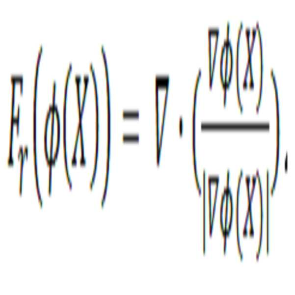
최종적으로 다음과 같은 세부분할을 위한 전진방정식을 얻게 된다.Finally, we obtain the forward equations for the subdivision as follows.
![]()
![]()
여기에서, 함수g는 원영상인 I에 의존하는 함수로서 다음과 같이 정의되었으며,Here, the function g is a function dependent on the original image I, and is defined as follows.

에지 위에서 0에 가까운 값을 가지고, 에지가 아닌 스무스(smooth) 영역에서는 1에 가까운 값을 가지므로, 에지 지시(edge indicator) 함수라고 불린다(도 16 참조). τ가 커지면 g는 명암에 관한 작은 변화에도 민감하여 대부분의 픽셀들을 에지로 나타낸다. 적절한 τ의 사용은 원하는 에지들만을 어두운 부분으로 표현할 수있다. 예를 들어, τ=1000이 사용될 수 있다. 국소힘인 ![]()
![]()
결과적으로, 식 (7)에서 첫 번째항 ![]()
![]()
![]()
![]()
![]()
![]()
![]()
As a result, in equation (7), the first term ![]()
![]()
![]()
![]()
![]()
![]()
![]()
3차원 재구성부(140)는 목적영역 분할부(130)를 통하여 추출된 피부 영역 및 하악골을 이용하여 3차원 모델로 재구성한다.The three-
목적영역 분할부(130)를 통해 하악골을 0-레벨로 나타내는 레벨 셋 함수![]()
![]()
또한 도 19 및 20은 기존 방법대비 본 방법의 우수성을 보여준다. 기존의방법은 mimics 소프트웨어를 이용하여 등값(iso-value)조절을 통한 초기 분할 후 다양한 후처리 과정을 통해 얻어진 결과이며, 이러한 방법은 불규칙한 경계를 가지는 목표물을 분할할 때 어려움을 가진다. 약한 경계를 추출하기 위해 등값을 낮게 조절함으로써 주변의 불필요한 부분까지 잡아낼 뿐만 아니라, 원하는 목표물의 경계보다 바깥부분을 잡는 경향을 띤다. 이에 비해 본 특허에서 제시한 방법은 목표물의 경계만을 적합한 위치에서 찾을 수 있다.
Figures 19 and 20 also illustrate the superiority of the present method over conventional methods. The existing method is a result obtained through various post-processing steps after initial segmentation through iso-value adjustment using mimics software, and this method has difficulty in dividing a target having irregular boundaries. In order to extract a weak boundary, it is necessary not only to catch unnecessary portions around the target by lowering the threshold value but also tends to catch the outer portion than the boundary of the desired target. In contrast, the method presented in this patent only finds the target boundary at the appropriate location.
제어부(150)는 영상 데이터 수신부(110), 다중영역 분할부(120), 목적영역 분할부(130), 및 3차원 재구성부(140)의 동작 및 데이터의 흐름을 제어한다.
The
도 2는 도 1의 3자동 영상 분할과 모델 형성 서버에서 수행되는 자동 의료영상 분할에 의한 3차원 악안면 모델 형성 방법에 대한 흐름도이다.FIG. 2 is a flowchart illustrating a method for forming a three-dimensional model of the facial model by automatic image segmentation and automatic modeling of the medical image segmentation in FIG.
영상 데이터 수신부(110)는 2차원 영상들의 집합인 3차원 의료 영상 데이터를 수신한다(단계 S210). 여기에서, 3차원 의료 영상 데이터는 CBCT 영상일 수 있다.The image
다중영역 분할부(120)는 3차원 의료 영상 데이터의 명암에 관한 명암 히스토그램을 구하고, 명암 히스토그램을 기초로 3차원 의료 영상 데이터를 다중영역으로 분할한다(단계 S220). 여기에서, 다중영역은 명암에 따라 라벨링 될 수 있다. 보다 구체적으로, 다중영역 분할부(120)는 명암의 범위를 256개의 계급으로 나누고 3차원 의료 영상 데이터에서 각 계급에 해당하는 명암을 가진 픽셀의 개수를 산출하여 명암 히스토그램을 구한다. 그런 다음, 명암 히스토그램에서 AGMC(Adaptive Global Maximum Clustering) 기법을 이용하여 특정 기준을 충족하는 피크를 가지는 부분 영역을 추출하고, 부분 영역의 명암 히스토그램의 평균 값을 기초로 3차원 의료 영상 데이터를 다중영역을 분할한다.The
목적영역 분할부(130)의 피부 세부 분할 모듈(131)은 다중영역을 형태학적으로 처리하여 피부 영역을 추출한다(단계 S230). 보다 구체적으로, 피부 세부 분할 모듈(131)은 다중영역의 라벨 값에 따라 다중영역을 이진화 하여 얼굴 후보 영역을 구하고, 얼굴 후보 영역의 크기를 기초로 설정된 반지름 값 또는 기 설정된 반지름 값을 가지는 원형구조원소를 이용하여 얼굴 후보 영역을 침식한다. 다음으로, 얼굴 후보 영역의 침식 영역을 제한하고, 침식 영역과 공통되는 부분이 있는 연결 성분을 추출한 다음, 다시 원형구조원소를 이용하여 팽창한다.The
목적영역 분할부(130)의 하악골 세부 분할 모듈(132)은 2차원 영상들 각각에 대하여 레벨 셋 함수 기반의 액티브 컨투어 방법을 이용하는 2차원 세부분할기법을 통하여 자동으로 하악골을 추출한다(단계 S240). 보다 구체적으로, 하악골 세부 분할 모듈(132)은 2차원 영상들 중 샘플 영상에 대한 분할 결과를 추출하고, 샘플 영상에 대한 분할 결과를 이용하여 나머지 영상들에 대한 분할 결과를 모두 추출한다. 각 영상들에 대한 분할 결과는 초기 컨투어 설정, 명암 강조, 및 컨투어를 이동시키는 과정을 통하여 추?x된다.The
3차원 재구성부(140)는 목적영역 분할부(130)를 통해 추출된 피부 영역 및 하악골을 이용하여 3차원 모델로 재구성한다(단계 S250). 보다 구체적으로, 3차원 재구성부(140)는 서피스 렌더링 알고리즘을 이용하여 3차원 모델로 재구성하고, HC-라플라시안 알고리즘을 이용하여 재구성된 3차원 모델의 표면을 매끄럽게 처리한다.
The three-
전술한 본 발명에 따른 자동 의료영상 분할에 의한 3차원 악안면 모델 형성 방법, 이를 수행하는 자동 영상 분할과 모델 형성 서버 및 이를 저장하는 기록매체에 대한 바람직한 실시예에 대하여 설명하였지만, 본 발명은 이에 한정되는 것이 아니고 특허청구범위와 발명의 상세한 설명 및 첨부한 도면의 범위 안에서 여러가지로 변형하여 실시하는 것이 가능하고 이 또한 본 발명에 속한다.
Although the present invention has been described with respect to a method for forming a three-dimensional mandibular image model by automatic medical image segmentation according to the present invention, an automatic image segmentation and model building server for performing the same, and a recording medium for storing the same, It is to be understood that the invention is not limited to the disclosed embodiments, but can be variously modified and embodied within the scope of the claims, the detailed description of the invention, and the accompanying drawings.
100: 자동 영상 분할과 모델 형성 서버
110: 영상 데이터 수신부
120: 다중영역 분할부
130: 목적영역 분할부
131: 피부 세부 분할 모듈
132: 하악골 세부 분할 모듈
140: 3차원 재구성부
150: 제어부100: Automatic image segmentation and modeling server
110:
120: Multi-region division unit
130: Destination area partitioning part
131: skin subdivision module
132: Mandibular subdivision module
140: 3D reconstruction unit
150:
Claims (21)
(a) 얼굴의 수평면에 대한 2차원 영상들의 집합인 3차원 의료 영상 데이터를 수신하는 단계;
(b) 상기 3차원 의료 영상 데이터의 명암의 분포를 기초로 명암 히스토그램을 구하고, 상기 명암 히스토그램을 기초로, 상기 얼굴에 대한 상기 3차원 의료 영상 데이터를 적어도 하나의 부분 영역으로 구분된 다중영역으로 분할하는 단계;
(c) 상기 얼굴에 대한 다중영역에서 상기 얼굴 이외의 부분을 제거하여 상기 얼굴 부분만 추출하고, 상기 얼굴 부분의 피부 영역을 추출하는 단계;
(d) 상기 얼굴의 수평면에 대한 2차원 영상들 각각에서, 레벨 셋 함수 기반의 액티브 컨투어 방법을 이용하는 2차원 세부분할기법을 통하여, 하악골을 추출하는 단계; 및
(e) 상기 추출된 피부 영역 및 하악골을 이용하여 3차원 모델로 재구성하는 단계를 포함하는 자동 영상 분할에 의한 3차원 모델 형성 방법.
A method for forming a three-dimensional model of skin and mandible by automatic image segmentation and automatic modeling server,
(a) receiving three-dimensional medical image data that is a set of two-dimensional images of a horizontal plane of a face;
(b) obtaining a light and dark histogram based on the distribution of light and dark of the three-dimensional medical image data, and based on the light and dark histogram, the three-dimensional medical image data for the face is divided into at least one Dividing;
(c) extracting only the face portion by removing a portion other than the face in the multiple regions for the face, and extracting a skin region of the face portion;
(d) extracting a mandible from each of two-dimensional images of the face of the face through a two-dimensional subdivision technique using an active contour method based on a level set function; And
(e) reconstructing a three-dimensional model using the extracted skin region and mandible.
상기 명암의 범위를 소정의 계급으로 나누고, 상기 얼굴에 대한 상기 3차원 의료 영상 데이터에서 상기 각 계급에 해당하는 명암을 가진 픽셀의 개수를 산출하여 상기 명암 히스토그램을 구하는 단계를 포함하는 것을 특징으로 하는 자동 영상 분할에 의한 3차원 모델 형성 방법.
2. The method of claim 1, wherein step (b)
And dividing the range of lightness and darkness by a predetermined class and calculating the number of pixels having lightness and darkness corresponding to each class in the three-dimensional medical image data for the face to obtain the light and dark histogram A method for forming a three - dimensional model by automatic image segmentation.
상기 명암 히스토그램에서 AGMC기법을 이용하여 특정 기준을 충족하는 피크를 가지는 부분 영역을 추출하는 단계를 더 포함하는 것을 특징으로 하는 자동 영상 분할에 의한 3차원 모델 형성 방법.
3. The method of claim 2, wherein step (b)
Further comprising extracting a partial region having a peak that meets a specific criterion using the AGMC technique in the contrast histogram.
상기 부분 영역의 명암 히스토그램의 평균 값을 기초로 상기 3차원 의료 영상 데이터를 다중영역으로 분할하는 단계를 더 포함하는 것을 특징으로 하는 자동 영상 분할에 의한 3차원 모델 형성 방법.
4. The method of claim 3, wherein step (b)
And dividing the 3D medical image data into multiple regions based on an average value of the contrast histogram of the partial region.
상기 다중영역의 라벨 값에 따라 상기 다중영역을 이진화하여 얼굴 후보 영역을 구하는 단계를 포함하는 것을 특징으로 하는 자동 영상 분할에 의한 3차원 모델 형성 방법.
2. The method of claim 1, wherein step (c)
And generating a face candidate region by binarizing the multi-region according to the label value of the multi-region.
상기 얼굴 후보 영역의 크기를 기초로 설정된 반지름 값 또는 기 설정된 반지름 값을 가지는 원형구조원소를 이용하여 상기 얼굴 후보 영역을 침식하는 단계를 더 포함하는 것을 특징으로 하는 자동 영상 분할에 의한 3차원 모델 형성 방법.
6. The method of claim 5, wherein step (c)
Further comprising the step of eroding the face candidate region using a circular structure element having a radius value or a predetermined radius value set based on the size of the face candidate region, Way.
상기 얼굴 후보 영역의 중심으로부터 좌우로 기 설정된 길이만큼 떨어진 위치까지 침식 영역을 제한하는 단계를 더 포함하는 것을 특징으로 하는 자동 영상 분할에 의한 3차원 모델 형성 방법.
7. The method of claim 6, wherein step (c)
Further comprising the step of restricting the erosion area to a position separated by a predetermined length from the center of the face candidate area to the right and left sides.
상기 침식 영역과 공통되는 부분이 있는 연결 성분을 추출하고 상기 원형구조원소를 이용하여 팽창하는 단계를 더 포함하는 것을 특징으로 하는 자동 영상 분할에 의한 3차원 모델 형성 방법.
8. The method of claim 7, wherein step (c)
Further comprising the step of extracting a connected component having a portion common to the eroded area and expanding using the circular structural element.
상기 2차원 영상들 중 샘플 영상을 선택하고, 상기 샘플 영상에 대한 분할 결과인 상기 샘플 영상에서의 하악골을 추출하는 단계를 포함하는 것을 특징으로 하는 자동 영상 분할에 의한 3차원 모델 형성 방법.
2. The method of claim 1, wherein step (d)
Selecting a sample image among the two-dimensional images, and extracting a mandible in the sample image as a result of the division of the sample image.
상기 샘플 영상의 분할 결과에 대한 컨투어를 기초로 상기 샘플 영상의 다음 또는 이전 영상의 초기 컨투어를 설정하는 단계를 더 포함하는 것을 특징으로 하는 자동 영상 분할에 의한 3차원 모델 형성 방법.
10. The method of claim 9, wherein step (d)
Further comprising setting an initial contour of a next or previous image of the sample image based on a contour of the division result of the sample image.
상기 초기 컨투어 내부의 하악골에 대한 명암 정보를 기초로 상기 하악골의 명암을 강조하는 단계를 더 포함하는 것을 특징으로 하는 자동 영상 분할에 의한 3차원 모델 형성 방법.
11. The method of claim 10, wherein step (d)
Further comprising the step of highlighting the contrast of the mandible based on the contrast information of the mandible inside the initial contour.
상기 초기 컨투어가 이동하여 상기 하악골의 경계에 닿으면 컨투어의 이동을 중단하는 단계를 더 포함하는 것을 특징으로 하는 자동 영상 분할에 의한 3차원 모델 형성 방법.
12. The method of claim 11, wherein step (d)
And stopping movement of the contour if the initial contour moves and touches the boundary of the mandible. ≪ Desc / Clms Page number 19 >
상기 컨투어가 상기 컨투어의 내부와 외부의 국소적 명암 평균값 및 상기 컨투어의 곡률을 기초로 이동하는 단계를 포함하는 것을 특징으로 하는 자동 영상 분할에 의한 3차원 모델 형성 방법.
13. The method of claim 12, wherein step (d)
And moving the contour based on a local intensity average value inside and outside the contour and a curvature of the contour.
서피스 렌더링 알고리즘을 이용하여 3차원 모델로 재구성하는 단계; 및
HC-라플라시안 알고리즘을 이용하여 상기 3차원 모델의 표면을 처리하는 단계를 포함하는 것을 특징으로 하는 자동 영상 분할에 의한 3차원 모델 형성 방법.
2. The method of claim 1, wherein step (e)
Reconstructing a 3D model using a surface rendering algorithm; And
And processing the surface of the three-dimensional model using an HC-Laplacian algorithm.
CBCT 영상 데이터인 것을 특징으로 하는 자동 영상 분할에 의한 3차원 모델 형성 방법.
2. The method according to claim 1, wherein the 3D medical image data
Wherein the CBCT image data is CBCT image data.
상기 다중영역의 명암에 따라 라벨링되어 있는 것을 특징으로 하는 자동 영상 분할에 의한 3차원 모델 형성 방법.
The method of claim 1, wherein the divided multi-
Wherein the image is labeled according to the contrast of the multiple regions.
얼굴의 수평면에 대한 2차원 영상들의 집합인 3차원 의료 영상 데이터를 수신하는 영상 데이터 수신부;
상기 3차원 의료 영상 데이터의 명암의 분포를 기초로 명암 히스토그램을 구하고, 상기 명암 히스토그램을 기초로, 상기 얼굴에 대한 상기 3차원 의료 영상 데이터를 적어도 하나의 부분 영역으로 구분된 다중영역으로 분할하는 다중영역 분할부;
상기 얼굴에 대한 다중영역에서 상기 얼굴 이외의 부분을 제거하여 상기 얼굴 부분만 추출하고, 상기 얼굴 부분의 피부 영역을 추출하는 피부 세부분할 모듈, 및 상기 얼굴의 수평면에 대한 2차원 영상들 각각에서, 레벨 셋 함수 기반의 액티브 컨투어 방법을 이용하는 2차원 세부분할기법을 통하여, 하악골을 추출하는 하악골 세부 분할 모듈을 포함하는 목적영역 분할부; 및
상기 추출된 피부 영역 및 하악골을 이용하여 3차원 모델로 재구성하는 3차원 재구성부를 포함하는 자동 영상 분할과 모델 형성 서버.
1. An automatic image segmentation and modeling server for performing a method of forming a three-dimensional model of skin and mandible by automatic medical image segmentation,
An image data receiving unit for receiving three-dimensional medical image data, which is a set of two-dimensional images of a horizontal plane of a face;
Dimensional medical image data is divided into at least one partial region divided into at least one partial region based on the light and dark histogram, and a histogram is obtained based on the distribution of light and darkness of the three- Area division;
A skin subdivision module for extracting only the face portion by extracting a portion other than the face in the multiple regions of the face and extracting a skin region of the face portion; A target region division unit including a mandible subdivision module for extracting a mandible through a 2D subdivision technique using an active contour method based on a level set function; And
And a three-dimensional reconstruction unit reconstructing the three-dimensional model using the extracted skin region and mandible.
상기 3차원 의료 영상 데이터에 대한 명암 히스토그램을 구하고, 상기 명암 히스토그램에서 특정 기준을 충족하는 피크를 가지는 부분 영역의 명암 히스토그램의 평균 값을 기초로, 상기 3차원 의료 영상 데이터를 다중영역으로 분할하는 것을 특징으로 하는 자동 영상 분할과 모델 형성 서버.
18. The apparatus of claim 17, wherein the multi-
Dividing the three-dimensional medical image data into multiple regions based on an average value of a light and dark histogram of a partial region having a peak satisfying a specific criterion in the light and dark histogram by obtaining a light and dark histogram of the three- Features automatic image segmentation and modeling server.
상기 다중영역에서 얼굴 후보 영역을 구하고, 상기 얼굴 후보 영역의 크기를 기초로 원형구조원소를 이용하여 상기 얼굴 후보 영역을 침식하고, 상기 얼굴 후보 영역의 길이를 기초로 침식 영역을 제한하고, 상기 침식영역과 공통되는 부분이 있는 연결 성분을 추출하고 상기 원형구조원소를 이용하여 팽창하는 것을 특징으로 하는 자동 영상 분할과 모델 형성 서버.
18. The method of claim 17, wherein the skin subdivision module
A face candidate region is obtained from the multiple regions, the face candidate region is eroded using a circular structural element based on the size of the face candidate region, the erosion region is limited based on the length of the face candidate region, And extracts a connected component having a common portion with the region and expands using the circular structural element.
상기 2차원 영상들 중 샘플 영상의 분할 결과에 대한 컨투어를 기초로 상기 샘플 영상의 다음 또는 이전 영상을 세부분할하여 하악골을 추출하는 것을 특징으로 하는 자동 영상 분할과 모델 형성 서버.
18. The method of claim 17, wherein the mandibular subdivision module
And extracting the next or previous image of the sample image based on a contour of the division result of the sample image among the two-dimensional images to extract the mandible.
Priority Applications (2)
| Application Number | Priority Date | Filing Date | Title |
|---|---|---|---|
| KR1020150132843A KR101718868B1 (en) | 2015-09-21 | 2015-09-21 | Method for forming 3d mazillofacial model by automatically segmenting medical image, automatic image segmentation and model formation server performing the same, and storage mdeium storing the same |
| US15/264,311 US9818186B2 (en) | 2015-09-21 | 2016-09-13 | Method for forming 3D maxillofacial model by automatically segmenting medical image, automatic image segmentation and model formation server performing the same, and storage medium storing the same |
Applications Claiming Priority (1)
| Application Number | Priority Date | Filing Date | Title |
|---|---|---|---|
| KR1020150132843A KR101718868B1 (en) | 2015-09-21 | 2015-09-21 | Method for forming 3d mazillofacial model by automatically segmenting medical image, automatic image segmentation and model formation server performing the same, and storage mdeium storing the same |
Publications (1)
| Publication Number | Publication Date |
|---|---|
| KR101718868B1 true KR101718868B1 (en) | 2017-03-22 |
Family
ID=58282712
Family Applications (1)
| Application Number | Title | Priority Date | Filing Date |
|---|---|---|---|
| KR1020150132843A KR101718868B1 (en) | 2015-09-21 | 2015-09-21 | Method for forming 3d mazillofacial model by automatically segmenting medical image, automatic image segmentation and model formation server performing the same, and storage mdeium storing the same |
Country Status (2)
| Country | Link |
|---|---|
| US (1) | US9818186B2 (en) |
| KR (1) | KR101718868B1 (en) |
Cited By (4)
| Publication number | Priority date | Publication date | Assignee | Title |
|---|---|---|---|---|
| KR101953629B1 (en) | 2017-11-21 | 2019-03-05 | 서울여자대학교 산학협력단 | Method and apparatus for automatic segmentation of the mandible using shape-constrained information in cranio-maxillo-facial cbct images |
| KR20200112309A (en) * | 2019-03-21 | 2020-10-05 | 울산대학교 산학협력단 | Method and apparatus for analyzing facial area image |
| CN112136157A (en) * | 2018-05-29 | 2020-12-25 | 麦迪西姆有限公司 | Method, system and computer program for segmenting tooth pulp regions from images |
| KR20210019815A (en) * | 2019-08-13 | 2021-02-23 | 주식회사 디오 | Method and apparatus for separating maxilla and mandible of 3-d oral ct image |
Families Citing this family (8)
| Publication number | Priority date | Publication date | Assignee | Title |
|---|---|---|---|---|
| EP3747349A1 (en) * | 2015-05-17 | 2020-12-09 | Endochoice, Inc. | Endoscopic image enhancement using contrast limited adaptive histogram equalization (clahe) implemented in a processor |
| SG10201706752XA (en) * | 2017-08-17 | 2019-03-28 | Iko Pte Ltd | Systems and methods for analyzing cutaneous conditions |
| CN110490851B (en) * | 2019-02-15 | 2021-05-11 | 腾讯科技(深圳)有限公司 | Mammary gland image segmentation method, device and system based on artificial intelligence |
| JP7269587B2 (en) * | 2019-10-07 | 2023-05-09 | 学校法人日本大学 | segmentation device |
| US11842484B2 (en) | 2021-01-04 | 2023-12-12 | James R. Glidewell Dental Ceramics, Inc. | Teeth segmentation using neural networks |
| CN113744384B (en) * | 2020-05-29 | 2023-11-28 | 北京达佳互联信息技术有限公司 | Three-dimensional face reconstruction method and device, electronic equipment and storage medium |
| CN116824059A (en) * | 2021-03-02 | 2023-09-29 | 武汉联影智融医疗科技有限公司 | Target surface reconstruction method, device, equipment and medium based on three-dimensional image |
| CN113920128B (en) * | 2021-09-01 | 2023-02-21 | 北京长木谷医疗科技有限公司 | Knee joint femur tibia segmentation method and device |
Citations (1)
| Publication number | Priority date | Publication date | Assignee | Title |
|---|---|---|---|---|
| KR20060028044A (en) | 2004-09-24 | 2006-03-29 | 유용석 | 3d finite element modeling method and recording materials using by 2d medical images |
Family Cites Families (3)
| Publication number | Priority date | Publication date | Assignee | Title |
|---|---|---|---|---|
| US9208558B2 (en) * | 1999-08-11 | 2015-12-08 | Osteoplastics Llc | Methods and systems for producing an implant |
| WO2001010339A2 (en) * | 1999-08-11 | 2001-02-15 | Case Western Reserve University | Method and apparatus for producing an implant |
| KR102146398B1 (en) * | 2015-07-14 | 2020-08-20 | 삼성전자주식회사 | Three dimensional content producing apparatus and three dimensional content producing method thereof |
-
2015
- 2015-09-21 KR KR1020150132843A patent/KR101718868B1/en active IP Right Grant
-
2016
- 2016-09-13 US US15/264,311 patent/US9818186B2/en active Active
Patent Citations (1)
| Publication number | Priority date | Publication date | Assignee | Title |
|---|---|---|---|---|
| KR20060028044A (en) | 2004-09-24 | 2006-03-29 | 유용석 | 3d finite element modeling method and recording materials using by 2d medical images |
Cited By (7)
| Publication number | Priority date | Publication date | Assignee | Title |
|---|---|---|---|---|
| KR101953629B1 (en) | 2017-11-21 | 2019-03-05 | 서울여자대학교 산학협력단 | Method and apparatus for automatic segmentation of the mandible using shape-constrained information in cranio-maxillo-facial cbct images |
| CN112136157A (en) * | 2018-05-29 | 2020-12-25 | 麦迪西姆有限公司 | Method, system and computer program for segmenting tooth pulp regions from images |
| CN112136157B (en) * | 2018-05-29 | 2024-04-26 | 麦迪西姆有限公司 | Method, system and computer program for segmenting dental pulp area from image |
| KR20200112309A (en) * | 2019-03-21 | 2020-10-05 | 울산대학교 산학협력단 | Method and apparatus for analyzing facial area image |
| KR102227439B1 (en) * | 2019-03-21 | 2021-03-15 | 울산대학교 산학협력단 | Method and apparatus for analyzing facial area image |
| KR20210019815A (en) * | 2019-08-13 | 2021-02-23 | 주식회사 디오 | Method and apparatus for separating maxilla and mandible of 3-d oral ct image |
| KR102277021B1 (en) | 2019-08-13 | 2021-07-14 | 주식회사 디오 | Method and apparatus for separating maxilla and mandible of 3-d oral ct image |
Also Published As
| Publication number | Publication date |
|---|---|
| US9818186B2 (en) | 2017-11-14 |
| US20170084026A1 (en) | 2017-03-23 |
Similar Documents
| Publication | Publication Date | Title |
|---|---|---|
| KR101718868B1 (en) | Method for forming 3d mazillofacial model by automatically segmenting medical image, automatic image segmentation and model formation server performing the same, and storage mdeium storing the same | |
| US11776216B2 (en) | System and method for extracting a region of interest from volume data | |
| JP6877868B2 (en) | Image processing equipment, image processing method and image processing program | |
| Saha et al. | Digital topology and geometry in medical imaging: a survey | |
| WO2018120644A1 (en) | Blood vessel extraction method and system | |
| US9659364B2 (en) | Probabilistic refinement of model-based segmentation | |
| US8750585B2 (en) | Method and system for segmenting a liver object in an image | |
| CN108038862B (en) | Interactive medical image intelligent segmentation modeling method | |
| Xia et al. | Individual tooth segmentation from CT images scanned with contacts of maxillary and mandible teeth | |
| JP6539303B2 (en) | Transforming 3D objects to segment objects in 3D medical images | |
| KR101099732B1 (en) | The tooth segmentation system for 3d modeling of individual tooth from ct or mri image | |
| JP2017524432A (en) | User-induced shape morphing in bone segmentation for medical imaging | |
| US20080107318A1 (en) | Object Centric Data Reformation With Application To Rib Visualization | |
| BRPI0613102A2 (en) | cut and paste video object | |
| CN111724389B (en) | Method, device, storage medium and computer equipment for segmenting CT image of hip joint | |
| Singh et al. | Automatic blastomere detection in day 1 to day 2 human embryo images using partitioned graphs and ellipsoids | |
| KR101831340B1 (en) | Method and apparatus for automatic segmentation of renal parenchyma using graph-cuts with shape constraint based on multi-probabilistic atlas in abdominal ct images | |
| Kaftan et al. | A two-stage approach for fully automatic segmentation of venous vascular structures in liver CT images | |
| Mortaheb et al. | Automatic dental CT image segmentation using mean shift algorithm | |
| Xianfen et al. | 3D semi-automatic segmentation of the cochlea and inner ear | |
| Lu et al. | An interactive approach to liver segmentation in CT based on deformable model integrated with attractor force | |
| CN109754469B (en) | Method and system for surface mesh cutting and kerf boundary optimization | |
| Nysjö et al. | BoneSplit-a 3D texture painting tool for interactive bone separation in CT images | |
| Kim et al. | Automatic lung segmentation in CT images using anisotropic diffusion and morphology operation | |
| Chen et al. | Automatic lung segmentation in HRCT images |
Legal Events
| Date | Code | Title | Description |
|---|---|---|---|
| E701 | Decision to grant or registration of patent right | ||
| GRNT | Written decision to grant | ||
| FPAY | Annual fee payment |
Payment date: 20200302 Year of fee payment: 4 |