US9816640B2 - Oil pressure control apparatus and method for setting oil-pressure characteristic - Google Patents
Oil pressure control apparatus and method for setting oil-pressure characteristic Download PDFInfo
- Publication number
- US9816640B2 US9816640B2 US14/728,207 US201514728207A US9816640B2 US 9816640 B2 US9816640 B2 US 9816640B2 US 201514728207 A US201514728207 A US 201514728207A US 9816640 B2 US9816640 B2 US 9816640B2
- Authority
- US
- United States
- Prior art keywords
- spool
- inlet
- discharge
- force
- sleeve
- Prior art date
- Legal status (The legal status is an assumption and is not a legal conclusion. Google has not performed a legal analysis and makes no representation as to the accuracy of the status listed.)
- Expired - Fee Related, expires
Links
Images


Classifications
-
- F—MECHANICAL ENGINEERING; LIGHTING; HEATING; WEAPONS; BLASTING
- F16—ENGINEERING ELEMENTS AND UNITS; GENERAL MEASURES FOR PRODUCING AND MAINTAINING EFFECTIVE FUNCTIONING OF MACHINES OR INSTALLATIONS; THERMAL INSULATION IN GENERAL
- F16K—VALVES; TAPS; COCKS; ACTUATING-FLOATS; DEVICES FOR VENTING OR AERATING
- F16K31/00—Actuating devices; Operating means; Releasing devices
- F16K31/02—Actuating devices; Operating means; Releasing devices electric; magnetic
- F16K31/06—Actuating devices; Operating means; Releasing devices electric; magnetic using a magnet, e.g. diaphragm valves, cutting off by means of a liquid
- F16K31/0675—Electromagnet aspects, e.g. electric supply therefor
-
- F—MECHANICAL ENGINEERING; LIGHTING; HEATING; WEAPONS; BLASTING
- F16—ENGINEERING ELEMENTS AND UNITS; GENERAL MEASURES FOR PRODUCING AND MAINTAINING EFFECTIVE FUNCTIONING OF MACHINES OR INSTALLATIONS; THERMAL INSULATION IN GENERAL
- F16K—VALVES; TAPS; COCKS; ACTUATING-FLOATS; DEVICES FOR VENTING OR AERATING
- F16K31/00—Actuating devices; Operating means; Releasing devices
- F16K31/02—Actuating devices; Operating means; Releasing devices electric; magnetic
- F16K31/06—Actuating devices; Operating means; Releasing devices electric; magnetic using a magnet, e.g. diaphragm valves, cutting off by means of a liquid
- F16K31/0603—Multiple-way valves
- F16K31/061—Sliding valves
- F16K31/0613—Sliding valves with cylindrical slides
-
- G—PHYSICS
- G05—CONTROLLING; REGULATING
- G05D—SYSTEMS FOR CONTROLLING OR REGULATING NON-ELECTRIC VARIABLES
- G05D16/00—Control of fluid pressure
- G05D16/20—Control of fluid pressure characterised by the use of electric means
- G05D16/2006—Control of fluid pressure characterised by the use of electric means with direct action of electric energy on controlling means
- G05D16/2013—Control of fluid pressure characterised by the use of electric means with direct action of electric energy on controlling means using throttling means as controlling means
- G05D16/202—Control of fluid pressure characterised by the use of electric means with direct action of electric energy on controlling means using throttling means as controlling means actuated by an electric motor
Definitions
- the present disclosure relates to an oil pressure control apparatus and a method for setting an oil-pressure characteristic of the oil pressure control apparatus.
- An oil pressure control device is widely known in the art.
- a spool is movably accommodated in a sleeve, so that the spool is reciprocated inside of the sleeve.
- the sleeve has an inlet port into which working oil is inputted, an outlet port from which the working oil is outputted and a discharge port from which a part of the working oil flowing from the inlet port to the outlet port is discharged.
- an electromagnetic thrust force is generated by a solenoid in accordance with a command value of electric current.
- the electromagnetic thrust force and an elastic restoring force of an elastic member (a spring) are applied to the spool in an axial direction of the spool.
- the electromagnetic thrust force and the elastic restoring force are opposed to each other in the axial direction, so that the spool is reciprocated in the sleeve.
- An amount of the working oil discharged from the discharge port is adjusted in order to control an output oil pressure of the working oil outputted from the outlet port.
- Japanese Patent Publication No. 2013-24406 discloses an oil pressure control valve, more exactly, a method for setting a characteristic of an output oil pressure with respect to a command value (equal to electric power supplied to the oil pressure control valve), that is, a command-response characteristic. More exactly, a command-response characteristic at a reference oil temperature is actually measured as a reference characteristic. And the command-response characteristics for each oil temperature are set by use of the reference characteristic.
- an inlet port, an outlet port and a discharge port which are formed in a cylindrical wall of a sleeve, are arranged in this order.
- a spool has several lands arranged in an axial direction thereof, so that each of the lands of the spool is in a sliding contact with an inner peripheral surface of the sleeve, to thereby form interfacial surfaces between an outer peripheral surface of each land and the corresponding inner peripheral surface of the sleeve.
- the outer peripheral surface of the spool and the inner peripheral surface of the sleeve are overlapped with each other in a radial direction of the sleeve.
- the inventors of the present disclosure found out, through their researches for setting the command-response characteristic, that the command-response characteristic varies even in a case both of the axial length of the overlapping area and the clearance width in the radial direction are not changed.
- the inventors found out that the command-response characteristic varies as a result that an electromagnetic thrust force and an elastic restoring force are inevitably changed because of their tolerances. Accordingly, it was found out that accuracy for setting the command-response characteristic is decreased.
- the present disclosure is made in view of the above problem. It is an object of the present disclosure to provide an oil pressure control apparatus and a method of setting a command-response characteristic of the oil pressure control apparatus, according to which accuracy for setting the command-response characteristic can be increased.
- an oil pressure control apparatus comprises;
- a sleeve of a cylindrical shape having an inlet port into which working oil is inputted, an outlet port from which the working oil is outputted and a discharge port from which a part of the working oil passing from the inlet port to the outlet port is discharged, wherein the inlet port, the outlet port and the discharge port are formed in a cylindrical wall of the sleeve in this order in a spring-biasing direction;
- a spool movably accommodated in the sleeve and having an inlet-side land and a discharge-side land in this order in the spring-biasing direction, so that an outer peripheral surface of each land of the spool is in a sliding contact with an inner peripheral surface of the cylindrical wall of the sleeve, wherein an inlet-side interfacial surface is formed at an inlet-side overlapping area between the inlet port and the outlet port, so that the outer peripheral surface of the inlet-side land of the spool and the inner peripheral surface of the cylindrical wall are overlapped with each other in a radial direction of the sleeve, and wherein a discharge-side interfacial surface is formed at a discharge-side overlapping area between the outlet port and the discharge port, so that the outer peripheral surface of the discharge-side land of the spool and the inner peripheral surface of the cylindrical wall are overlapped with each other in the radial direction of the sleeve;
- a solenoid provided at one of axial ends of the sleeve for generating an electromagnetic thrust force in accordance with a command value of electric power supplied to the solenoid, so that the electromagnetic thrust force is applied to one of axial ends of the spool in an axial direction of the sleeve for biasing the spool in a direction opposite to the spring-biasing direction;
- an elastic member provided at the other of the axial ends of the sleeve for generating an elastic restoring force in accordance with a stroke position of the spool with respect to the sleeve, so that the elastic restoring force is applied to the other of the axial ends of the spool in the axial direction of the sleeve for biasing the spool in the spring-biasing direction toward the solenoid,
- the spool is reciprocated in the sleeve depending on a balance of the electromagnetic thrust force and the elastic restoring force in the axial direction, so as to adjust an amount of the working oil to be discharged from the discharge port to thereby control an output oil pressure of the working oil outputted from the outlet port.
- a method for setting a characteristic of the output oil pressure with respect to the command value as a command-response characteristic comprises;
- a second step for calculating a stroke-response characteristic which is a characteristic of the output oil pressure with respect to the stroke position of the spool, wherein a calculation of the second step is carried out based on the reference I-P characteristic actually measured in the first step, a thrust-force correlation which is a correlation of the electromagnetic thrust force with respect to the stroke position of the spool for each command value, and a restoring-force correlation which is a correlation of the elastic restoring force with respect to the stroke position of the spool;
- a third step for estimating an overlapping length and a clearance width based on the stroke-response characteristic calculated in the second step, wherein the overlapping length is a total length of the inlet-side overlapping area formed in the inlet-side interfacial surface and the discharge-side overlapping area formed in the discharge-side interfacial surface in the axial direction of the sleeve, and wherein the clearance width is a width of an inlet-side clearance and a discharge-side clearance each of which is respectively formed in the inlet-side interfacial surface and in the discharge-side interfacial surface in the radial direction of the sleeve; and
- a fourth step for deciding the command-response characteristic for each oil temperature based on the overlapping length and the clearance width each estimated in the third step as well as the reference I-P characteristic actually measured in the first step.
- the oil pressure control apparatus has an electronic control unit in addition to the above sleeve, the spool, the solenoid and the elastic member.
- the electronic control unit comprises;
- a reference memorizing portion for memorizing a reference I-P characteristic, which is a command-response characteristic of the output oil pressure with respect to the command value and actually measured at a reference oil temperature;
- a calculation portion for calculating a stroke-response characteristic of the output oil pressure with respect to the stroke position of the spool, based on the reference I-P characteristic memorized in the reference memorizing portion, a thrust-force correlation which is a correlation of the electromagnetic thrust force with respect to the stroke position for each command value, and a restoring-force correlation which is a correlation of the elastic restoring force with respect to the stroke position;
- an estimation portion for estimating an overlapping length and a clearance width based on the stroke-response characteristic calculated in the calculation portion, wherein the overlapping length is a total length of the inlet-side overlapping area formed in the inlet-side interfacial surface and the discharge-side overlapping area formed in the discharge-side interfacial surface in the axial direction of the sleeve, and wherein the clearance width is a width of an inlet-side clearance and a discharge-side clearance each of which is respectively formed in the inlet-side interfacial surface and in the discharge-side interfacial surface in the radial direction of the sleeve; and
- a decision portion for deciding the command-response characteristic for each oil temperature based on the overlapping length and the clearance width each estimated in the estimation portion as well as the reference I-P characteristic memorized in the reference memorizing portion.
- the characteristic of the output oil pressure with respect to the stroke position of the spool is calculated based on the reference I-P characteristic, which corresponds to the command-response characteristic actually measured at the reference oil temperature.
- the above stroke-response characteristic is based on not only the thrust-force correlation (which is the correlation of the electromagnetic thrust force with respect to the stroke position for each command value) but also the restoring-force correlation (which is the correlation of the elastic restoring force with respect to the stroke position).
- the tolerances of the electromagnetic thrust force and the elastic restoring force can be also reflected to the estimated values for the overlapping length and the clearance width.
- the command-response characteristic for each oil temperature is decided, the actually measured reference I-P characteristic and the exactly-estimated overlapping length and the clearance width based on the stroke-response characteristic are used. It is, therefore, possible to increase the accuracy for setting the command-response characteristic for each oil temperature.
- FIG. 1 is a diagram showing an outline of a structure of a control system for an automatic transmission apparatus, to which an oil pressure control apparatus according to a first embodiment of the present disclosure is applied;
- FIG. 2 is a schematically enlarged cross sectional view showing the oil pressure control device of the first embodiment
- FIG. 3 is a schematic view of the oil pressure control device for explaining an operation thereof, when a stroke position of a sleeve is in a land-overlap range;
- FIG. 4 is also a schematic view of the oil pressure control device for explaining the operation thereof, when the stroke position of the sleeve is in a notch communication range;
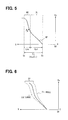
- FIG. 5 is a graph showing a stroke-response characteristic of the oil pressure control device
- FIG. 6 is a graph for explaining variations of the stroke-response characteristic of FIG. 5 ;
- FIG. 7 is another graph for explaining the variations of the stroke-response characteristic of FIG. 5 ;
- FIG. 8 is a graph showing a reference characteristic for a command-response characteristic of the oil pressure control device according to the first embodiment
- FIGS. 9A and 9B are graphs for explaining a relationship between the command-response characteristic of FIG. 8 and a conversion correlation of FIG. 10 , in association with the stroke-response characteristic of FIG. 5 ;
- FIG. 10 is a graph showing characteristics of a difference-force correlation and the conversion correlation of the oil pressure control device
- FIG. 11 is a graph showing characteristics of a thrust-force correlation of the oil pressure control device
- FIG. 12 is a graph showing a characteristic of a restoring-force correlation of the oil pressure control device
- FIG. 13 is a flowchart showing a process for setting the command-response characteristics of the oil pressure control device
- FIG. 14 is a schematic cross sectional view for explaining a process of measuring the thrust-force correlation
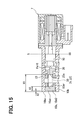
- FIG. 15 is a schematic cross sectional view for explaining a process of measuring the restoring-force correlation
- FIGS. 16A and 16B are graphs, similar to FIGS. 9A and 9B , for explaining a comparing step of a calculation step shown in FIG. 13 ;
- FIGS. 17A, 17B and 17C are characteristic graphs for explaining a deciding step shown in FIG. 13 ;
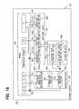
- FIG. 18 is a block diagram showing a control circuit of an oil pressure control device according to a second embodiment of the present disclosure.
- an oil pressure control apparatus 9 according to a first embodiment of the present disclosure is applied to an automatic transmission control system 2 in order to control oil pressure of working oil for an automatic transmission apparatus 1 of a vehicle.
- the automatic transmission apparatus 1 is composed of a combination of multiple friction elements 3 , such as, a clutch member, a brake member and so on (only one friction element 3 is shown in FIG. 1 ).
- a predetermined number of the friction plates 3 b are connected to or disconnected from each other in accordance with the oil pressure of the working oil applied to a piston chamber 3 a , to thereby change a range or a transmission gear ratio of the vehicle.
- the automatic transmission control system 2 is composed of an oil pump 4 , an oil pan 5 , a manual valve 6 , an oil pressure control valve 7 , an electronic control circuit 8 , and so on.
- the oil pump 4 draws the working oil from the oil pan 5 (working as a drain) and pumps out the working oil to the manual valve 6 .
- the manual valve 6 is connected to the oil pump 4 and connected to the oil pressure control valve 7 , which is provided for every three friction elements 3 , although only one friction element 3 is shown in FIG. 1 .
- the manual valve 6 changes a valve position of the respective oil pressure control valves 7 depending on a position of a shift lever 6 a operated by a vehicle driver, wherein the working oil is supplied from the oil pump 4 to each of the oil pressure control valves 7 .
- the oil pressure control valve 7 is an electromagnetically operated spool valve.
- the oil pressure control valve 7 is operated in accordance with a command value “I” of electric power, which is supplied to the oil pressure control valve 7 as an electric current value.
- Each of the oil pressure control valves 7 outputs the working oil to be applied to the respective friction elements 3 , when the working oil is supplied to the oil pressure control valve 7 .
- the oil pressure control valve 7 controls an output oil pressure “Po” depending on the pressure of the working oil from the oil pump 4 via the manual valve 6 .
- the electronic control circuit 8 which is mainly composed of a micro-computer having a memory device 80 , is electrically connected to each of the oil pressure control valves 7 .
- the electronic control circuit 8 controls the electric current supplied to each of the oil pressure control valves 7 in order to change the transmission gear ratio depending on an operating condition of the vehicle.
- the oil pressure control apparatus 9 is composed of multiple oil pressure control valves 7 and one common control circuit 8 , wherein each of the oil pressure control valves 7 has the same structure to the other oil pressure control valves. Therefore, in FIG. 1 , only one of the oil pressure control valves 7 is shown and a further detailed explanation will be made for such one of the oil pressure control valves 7 .
- the oil pressure control valve 7 of the present embodiment is a linear solenoid valve of a normally-closed type.
- the oil pressure control valve 7 is composed of a sleeve 10 , a spool 20 , an elastic member 30 , a stator 40 , a movable shaft 50 , a plunger 60 , a solenoid 70 and so on.
- the sleeve 10 which is made of metal, is formed in a cylindrical shape as a whole.
- a bottom wall 10 a of the sleeve 10 is composed of an adjusting screw 10 as , which is threadably inserted into one axial end of a cylindrical wall 10 b of the sleeve 10 .
- An inlet port 11 , an outlet port 12 , a discharge port 13 , a feedback port 14 and drain ports 15 a and 15 b are respectively formed in the cylindrical wall 10 b , wherein each of the ports passes through the cylindrical wall 10 b in a radial direction.
- the working oil is supplied from the oil pump 4 to the inlet port 11 via the manual valve 6 .
- the outlet port 12 is located at a position of the cylindrical wall 10 b opposite to the inlet port 11 in the radial direction of the sleeve 10 to the solenoid 70 .
- the outlet port 12 is located at the position, which is more separated from the bottom wall 10 a in an axial direction of the sleeve 10 than the inlet port 11 .
- the working oil which is controlled at the output oil pressure “Po”, is outputted from the outlet port 12 and supplied to the corresponding piston chamber 3 a of the automatic transmission apparatus 1 .
- the discharge port 13 is located at a position of the cylindrical wall 10 b opposite to the outlet port 12 in the radial direction of the sleeve 10 .
- the discharge port 13 is located at the position, which is more separated from the bottom wall 10 a in the axial direction to the solenoid 70 than the outlet port 12 .
- a part of the working oil flowing from the inlet port 11 to the outlet port 12 that is, an extra amount of the working oil, is discharged from the discharge port 13 to the oil pan 5 .
- the feedback port 14 is located at a position of the cylindrical wall 10 b , which is on a side of the inlet port 11 closer to the bottom wall 10 a in the axial direction.
- the output oil pressure “Po” of the working oil from the outlet port 12 is feed-backed to the feedback port 14 , as indicated by arrows in FIGS. 3 and 4 .
- the drain port 15 a is located at a position of the cylindrical wall 10 b , which is on a side of the feedback port 14 closer to the bottom wall 10 a in the axial direction.
- the working oil which is leaked into a space between the feedback port 14 and the bottom wall 10 a , is discharged from the drain port 15 a to the oil pan 5 .
- the drain port 15 b is located at a position of the cylindrical wall 10 b , which is on a side of the discharge port 13 opposite to the inlet port 12 in the axial direction.
- the working oil which is leaked into a space between the stator 40 and the discharge port 13 , is discharged from the drain port 15 b to the oil pan 5 .
- an inlet-side inner peripheral portion 16 is formed by a part of an inner peripheral surface of the cylindrical wall 10 b between the inlet port 11 and the outlet port 12 in the axial direction.
- a discharge-side inner peripheral portion 17 is formed by another part of the inner peripheral surface of the cylindrical wall 10 b between the outlet port 12 and the discharge port 13 in the axial direction.
- a feedback-side inner peripheral portion 18 is formed by a further part of the inner peripheral surface of the cylindrical wall 10 b between the inlet port 11 and the feedback port 14 in the axial direction.
- Each of a first and a second drain-side inner peripheral portions 19 a and 19 b is formed by a still further part of the inner peripheral surface of the cylindrical wall 10 b between the feedback port 14 and the drain port 15 a and between the discharge port 13 and the drain port 15 b in the axial direction.
- each of inner diameters for the respective inner peripheral portions 16 , 17 , 18 and 19 b , except for the first drain-side inner peripheral portion 19 a is set at a value ( ⁇ sll), which is substantially identical to one another.
- An inner diameter ( ⁇ sls) of the first drain-side inner peripheral portion 19 a is made smaller than the inner diameter ( ⁇ sll) of the other inner peripheral portions 16 , 17 , 18 and 19 b.
- the spool 20 which is made metal, is formed in a cylindrical shape as a whole, wherein the spool 20 has multiple land portions.
- the spool 20 is coaxially accommodated in the sleeve 10 and movable with respect to the cylindrical wall 10 b in the axial direction in a reciprocating manner.
- a stroke position “S” of the spool 20 is indicated by a moving amount of the spool 20 , which is moved from a reference position “S 0 ”.
- the reference position “S 0 ” corresponds to a moving end of the spool 20 in the axial direction toward the stator 40 .
- the spool 20 has a discharge-side land 21 , an inlet-side land 22 and a feedback-side land 23 in this order in the axial direction from a side of the stator 40 toward the bottom wall 10 a .
- each of outer diameters of the discharge-side land 21 and the inlet-side land 22 is set at a value ( ⁇ spl), which is substantially equal to each other.
- An outer diameter ( ⁇ sps) of the feedback-side land 23 is made smaller than the outer diameter ( ⁇ spl) of the other lands 21 and 22 .
- a right-hand portion of the discharge-side land 21 is always in a sliding contact with the second drain-side inner peripheral portion 19 b on the side of the discharge port 13 .
- a left-hand portion of the discharge-side land 21 is also in a sliding contact with the discharge-side inner peripheral portion 17 .
- a left-hand portion of the inlet-side land 22 is always in a sliding contact with the feedback-side inner peripheral portion 18 .
- a right-hand portion of the inlet-side land 22 is also in a sliding contact with the inlet-side inner peripheral portion 16 ( FIGS. 3 and 4 ).
- the feedback-side land 23 is always in a sliding contact with the first drain-side inner peripheral portion 19 a on the side of the feedback port 14 .
- a feedback-side oil chamber is formed in the cylindrical wall 10 b between the feedback-side land 23 and the inlet-side land 22 . Therefore, the output oil pressure “Po”, which is feed-backed from the outlet port 12 to the feedback port 14 , is applied to the inlet-side land 22 and the feedback-side land 23 at the same time, so that a feedback force “Ffb” is generated in accordance with the output oil pressure “Po”. Since the outer diameter “ ⁇ spl” of the inlet-side land 22 is larger than the outer diameter “ ⁇ sps” of the feedback-side land 23 , a pressure receiving area of the inlet-side land 22 is larger than that of the feedback-side land 23 .
- notched portions 22 a are formed at an outer peripheral portion of the inlet-side land 22 on an axial side thereof facing the discharge-side land 21 (that is, on the right-hand portion of the inlet-side land 22 ).
- Each of the notched portions 22 a is recessed in a radial-inward direction from an outer peripheral surface 22 b of the inlet-side land 22 .
- each of the notched portions 22 a is recessed in the axial direction from an axial end surface 22 c of the inlet-side land 22 .
- a longitudinal length of each notched portion 22 a is smaller than that of the inlet-side land 22 , so that each notched portion 22 a does not reach another axial end surface 22 d of the inlet-side land 22 opposite to the axial end surface 22 c .
- the longitudinal length of each notched portion 22 a corresponds to a longitudinal length “Lnc” of a notch-communication range “NC”, which is formed by the notched portion 22 a when the notched portion 22 a is opened (explained below).
- the elastic member 30 is composed of a coil spring made of metal and formed in a coil shape.
- the elastic member 30 is coaxially accommodated in the sleeve 10 with the spool 20 , so that the elastic member 30 is arranged inside of the cylindrical wall 10 b between the bottom wall 10 a and the feedback-side land 23 of the spool 20 .
- An elastic restoring force “Fel” is generated due to a compressive deformation of the elastic member 30 in accordance with the stroke position “S” of the spool 20 ( FIGS. 3 and 4 ).
- the elastic restoring force “Fel” is applied to the feedback-side land 23 , the spool 20 is biased in the axial direction to the stator 40 .
- the stator 40 made of magnetic material is formed in a cylindrical shape.
- the stator 40 is fixed to the sleeve 10 so as to be coaxial with an opening portion 10 c of the cylindrical wall 10 b .
- the stator 40 has a small-diameter through-hole 41 and a large-diameter through-hole 42 at its center.
- the small-diameter through-hole 41 is formed in the stator 40 on a side to the sleeve 10
- the large-diameter through-hole 42 is formed in the stator 40 on an opposite side to the small-diameter through-hole 41 in the axial direction.
- the movable shaft 50 is made of metal and formed in a small-diameter rod shape.
- the movable shaft 50 is coaxially accommodated in the stator 40 , so that the movable shaft 50 is movable in a reciprocating manner with respect to the small-diameter through-hole 41 in the axial direction.
- the plunger 60 is made of magnetic material and formed in a rod shape having a diameter larger than that of the movable shaft 50 .
- the plunger 60 is arranged in the stator 40 on a side of the movable shaft 50 opposite to the sleeve 10 in the axial direction.
- the plunger 60 is coaxially accommodated in the stator 40 and movable in the reciprocating manner with respect to the large-diameter through-hole 42 in the axial direction.
- the movable shaft 50 is always held in the axial direction between the plunger 60 and the spool 20 , which is biased by the elastic restoring force “Fel”, the plunger 60 is capable of reciprocating together with the spool 20 and the movable shaft 50 .
- the solenoid 70 is composed of a bobbin 71 made of resin and a coil wound on the bobbin 71 .
- the coil is arranged at an outer periphery of the stator 40 via the bobbin 71 .
- the solenoid 70 is electrically connected to the electronic control circuit 8 via a terminal 72 shown in FIGS. 1 and 2 .
- the solenoid 70 is energized when it receives the electric current from the electronic control circuit 8 as the command value “I”. As shown in FIGS. 3 and 4 , the solenoid 70 generates an electromagnetic thrust force “Fsol” in accordance with the command value “I”.
- the electromagnetic thrust force “Fsol” is applied from the plunger 60 to the spool 20 via the movable shaft 50 , so that the spool 20 is biased in the axial direction toward the bottom wall 10 a .
- the spool 20 receives the electromagnetic thrust force “Fsol” in the opposite direction to the elastic restoring force “Fel”.
- the electromagnetic thrust force “Fsol” balances with a sum of the elastic restoring force “Fel” and the feedback force “Ffb”, as indicated by the following equation 2, so that the stroke position “S” of the spool 20 is unambiguously decided.
- an amount of the working oil discharged from the discharge port 13 is adjusted to a value depending on the stroke position “S” of the spool 20 .
- the output oil pressure “Po” outputted from the outlet port 12 is thereby controlled.
- a land-overlap range “OL” is defined as a longitudinal inner peripheral area of the sleeve 10 , in which the entire area of the notched portion 22 a in the axial direction overlaps with the inlet-side inner peripheral portion 16 .
- An inlet-side interfacial surface “Bi” is formed in an inlet-side overlapping area, that is, in an area between the outer peripheral surface of the inlet-side land 22 and the inlet-side inner peripheral portion 16 in the radial direction and between the inlet port 11 and the outlet port 12 in the axial direction of the spool 20 , when the spool 20 is in the land-overlap range “OL”.
- a longitudinal length “Li” of the inlet-side interfacial surface “Bi” becomes larger when the spool 20 is moved in the direction to the stator 40 .
- a discharge-side interfacial surface “Be” is likewise formed in a discharge-side overlapping area, that is, in an area between the outer peripheral surface of the discharge-side land 21 and the discharge-side inner peripheral portion 17 in the radial direction and between the outlet port 12 and the discharge port 13 in the axial direction of the spool 20 , when the spool 20 is in the land-overlap range “OL”.
- a longitudinal length “Le” of the discharge-side interfacial surface “Be” becomes smaller as the spool 20 is more moved in the direction to the stator 40 .
- “Pi” is an input oil pressure of the working oil, which is inputted into the inlet port 11 .
- “ ⁇ L” is a total longitudinal length of the inlet-side and the discharge-side overlapping areas in the interfacial surfaces “Be” and “Bi”. Therefore, “ ⁇ L” is also referred to as “an overlapping length”.
- the notch-communication range “NC” is defined as a longitudinal inner peripheral area of the sleeve 10 , in which a part of the notched portion 22 a in the axial direction overlaps with the inlet-side inner peripheral portion 16 .
- the notch-communication range “NC” is formed next to the land-overlap range “OL”.
- the inlet-side interfacial surface “Bi” is also formed between the outer peripheral surface of the inlet-side land 22 and the inlet-side inner peripheral portion 16 in the radial direction and between the inlet port 11 and the outlet port 12 in the axial direction of the spool 20 , when the spool 20 is moved from the stroke position “S” in the land-overlap range “OL” ( FIG. 3 ) to the stroke position “S” in the notch-communication range “NC” ( FIG. 4 ).
- the longitudinal length “Li” of the inlet-side interfacial surface “Bi” becomes smaller when the spool 20 is moved from the land-overlap range “OL” to the notch-communication range “NC”.
- the discharge-side interfacial surface “Be” is likewise formed between the outer peripheral surface of the discharge-side land 21 and the discharge-side inner peripheral portion 17 in the radial direction and between the outlet port 12 and the discharge port 13 in the axial direction of the spool 20 , when the spool 20 is moved from the land-overlap range “OL” to the notch-communication range “NC”. Therefore, the longitudinal length “Le” of the discharge-side interfacial surface “Be” becomes larger as the spool 20 is moved more in the direction to the bottom wall 10 a.
- the amount of the working oil, which flows from the inlet port 11 to the outlet port 12 via the inlet-side clearance “CLi” of the inlet-side interfacial surface “Bi”, is increased, as the spool 20 is more moved in the direction to the bottom wall 10 a .
- the amount of the working oil, which flows from the inlet port 11 to the discharge port 13 via the discharge-side clearance “CLe” of the discharge-side interfacial surface “Be”, is decreased, as the spool 20 is more moved in the direction to the bottom wall 10 a .
- the output oil pressure “Po” of the working oil outputted from the outlet port 12 is thereby increased.
- ⁇ CL is a physical amount expressed by the equation 6.
- ⁇ CL is a width of the clearances “Cli” and “Cle” in the radial direction (hereinafter, “ ⁇ CL” is also referred to as “a clearance width”).
- the clearance width “ ⁇ CL” of the inlet-side clearance “CLi” is equal to the clearance width “ ⁇ CL” of the discharge-side clearance “CLe”.
- Each of “V 1 ” and “V 2 ” in the above equation 5 is a coefficient, which is respectively expressed by the above equations 7 and 8.
- “Cq”, “An” and “ ⁇ ” in the equation 7 are, respectively, a flow rate coefficient of the working oil, a minimum opening area in each of the notched portions 22 a , and a density of the working oil.
- “ ⁇ ” in the equation 8 is a viscosity of the working oil.
- the stroke-response characteristic “SP” varies depending on the overlapping length “ ⁇ L”, which corresponds to the total longitudinal length of respective overlapping areas in the interfacial surfaces “Bi” and “Be”.
- Each of the interfacial surfaces “Be” and “Bi” is formed between the inlet port 11 and the discharge port 13 in the axial direction, wherein the outlet port 12 is formed between the respective ports 11 and 13 . Therefore, when the overlapping length “ ⁇ L” becomes smaller, the output oil pressure “Po” in the land-overlap range “OL” is increased in accordance with the equation 4.
- a gradient of the stroke-response characteristic “SP” is increased in the land-overlap range “OL”.
- the stroke-response characteristic “SP” further varies depending on the clearance width “ ⁇ CL” for the interfacial surfaces “Bi” and “Be”. More exactly, when the clearance width “ ⁇ CL” becomes smaller, the output oil pressure “Po” is correspondingly increased in the notch-communication range “NC”, in accordance with the equation 5. Therefore, a gradient of the stroke-response characteristic “SP” is increased in the notch-communication range “NC”.
- the command-response characteristic “IP” is so set that the output oil pressure “Po” is obtained corresponding to each command value “I” (In FIG. 8 , the command values “I” are indicated by “I 1 ”, “I 2 ”, . . . “In ⁇ 1” and “In”).
- the command-response characteristic “IP” varies depending on the electromagnetic thrust force “Fsol” and/or the elastic restoring force “Fel”, even when the stroke-response characteristic “SP” is the same.
- a correlation of a difference force “ ⁇ F” with respect to the stroke position “S” for each command value “I” (“I 1 ”, “I 2 ”, . . . “In ⁇ 1” and “In” in FIG. 10 ) is defined as a difference-force correlation “DC”.
- a correlation of the electromagnetic thrust force “Fsol” with respect to the stroke position “S” for each command value “I” is defined as a thrust-force correlation “TC”.
- a correlation of the elastic restoring force “Fel” with respect to the stroke position “S” is defined as a restoring-force correlation “RC”, as shown in FIG. 12 .
- the difference-force correlation “DC” of FIG. 10 is obtained by combining the thrust-force correlation “TC” of FIG. 11 with the restoring-force correlation “RC” of FIG. 12 for each stroke position “S”.
- each value of the difference force “ ⁇ F” of the difference-force correlation “DC” can be converted into the output oil pressure “Po” by use of the equation 3.
- the output oil pressure “Po” converted from the difference-force correlation “DC” (that is, the correlation of the output oil pressure “Po” with respect to the stroke position “S” for each command value “I”) is defined as a conversion correlation “DCc”.
- FIG. 9A shows the conversion correlation “DCc” and the stroke-response characteristic “SP” with respect to the stroke position “S”.
- characteristic curves of the conversion correlation “DCc” are overlapped to the stroke-response characteristic “SP” for the same stroke positions “S”.
- solid lines show the conversion correlation “DCc”, in a case that each of the electromagnetic thrust force “Fsol” and the elastic restoring force “Fel” has a certain value.
- two-dot-chain lines show the conversion correlation “DCc”, in a case that the output oil pressure “Po” depending on the difference force “ ⁇ F” is changed as a result that at least one of the values of the electromagnetic thrust force “Fsol” and the elastic restoring force “Fel” is changed to a different value from the above certain value of the solid line.
- FIG. 9B shows a relationship between the output oil pressure “Po” and the command values “I”. More exactly, FIG. 9B shows the command-response characteristics “IP, IP 0 ” at each command values (“I 1 ”, “I 2 ”, “In ⁇ 1” and “In”), which corresponds to respective intersecting points of the conversion correlation “DCc” and the stroke-response characteristic “SP” in FIG. 9A .
- the process for setting the command-response characteristic “IP” according to the present embodiment is carried out in accordance with a flow-chart shown in FIG. 13 , for example, before the oil pressure control apparatus 9 is installed in the vehicle.
- step S 101 the thrust-force correlation “TC” and the restoring-force correlation “RC” are respectively obtained based on actually measured values. More exactly, at a step S 101 a (a thrust-force correlation measuring step), the thrust-force correlation “TC” is obtained based on the actually measured values of the electromagnetic thrust force “Fsol” for each stroke position “S”.
- the oil pressure control valve 7 is set to a measuring device 90 , as shown in FIG. 14 , in a condition that the adjusting screw 10 as and the elastic member 30 are removed from the sleeve 10 .
- the measuring device 90 is composed of a load cell 91 , a load transmitting member 92 , a range member 93 , a measuring sensor 94 and so on.
- the load cell 91 has a sensing surface 91 a for sensing a load, for example, by a strain gauge.
- the load transmitting member 92 follows a change of the stroke position “S” of the spool 20 , so that the load transmitting member 92 is continuously held between the sensing surface 91 a and a spring receiving surface 23 a of the feedback land 23 (which receives one axial end of the elastic member 30 , as shown in FIG. 2 ).
- a position of the range member 93 perpendicular to the axial direction of the spool 20 is maintained when the range member 93 is moved, in order that a contacting condition of the range member 93 with the sensing surface 91 a is maintained.
- the measuring sensor 94 is composed of, for example, an optical measuring instrument, an acoustic measuring instrument or the like, which measures a distance “ ⁇ D” to the range member 93 . Since the position of the range member 93 corresponds to the stroke position “S”, the stroke position “S” can be calculated based on the distance “ ⁇ D” measured by the measuring sensor 94 .
- the electromagnetic thrust force “Fsol” is measured for each measuring point “I 1 ”, “I 2 ”, . . . “In ⁇ 1” and “In” (the multiple points are set as the command value “I”), while the stroke position “S” is changed. Accordingly, the correlation of the electromagnetic thrust force “Fsol” with respect to the stroke position “S” for each command value “I”, that is, the thrust-force correlation “TC” of FIG. 11 is obtained.
- the restoring-force correlation “RC” is obtained based on actually measured values of longitudinal length “X 1 ”, “X 2 ” and “X 3 ”, when the spool 20 is located in its reference position “S 0 ”, as shown in FIG. 15 .
- the length “X 1 ” is a distance in the axial direction between the spring receiving surface 23 a and an outer axial end surface 10 be of the cylindrical wall 10 b , when the spool 20 is in the reference position “S 0 ”.
- the length “X 2 ” is a distance in the axial direction between an outer axial end surface 10 ae of the adjusting screw 10 as and the outer axial end surface 10 be of the cylindrical wall 10 b , when the spool 20 is in the reference position “S 0 ”.
- the length “X 2 ” corresponds to a screwed amount of the adjusting screw 10 as.
- the length “X 3 ” is a distance in the axial direction between the outer axial end surface 10 ae of the adjusting screw 10 as and a spring receiving surface 10 ar of the adjusting screw 10 as for receiving the other end of the elastic member 30 ( FIG. 2 ).
- the length “X 3 ” corresponds to a thickness of the adjusting screw 10 as (a thickness of the bottom wall 10 a ). Since each of the outer axial end surface 10 ae and the spring receiving surface 10 ar of the adjusting screw 10 as is formed by a flat surface, which is perpendicular to the axial direction of the spool 20 , it is possible to exactly measure the length “X 3 ”.
- the length “X 1 ” and the length “X 3 ” are measured in the condition that the adjusting screw 10 as and the elastic member 30 are removed from the sleeve 10 . Then, the length “X 2 ” is measured, after the elastic member 30 is accommodated in the sleeve 10 and the adjusting screw 10 as is screwed into the sleeve 10 .
- the constant “k” of spring and the natural length “L 0 ” are obtained in advance based on an actual measurement, which is carried out when checking specifications of the elastic member 30 .
- the correlation of the elastic restoring force “Fel” with respect to the stroke position “S”, that is, the restoring-force correlation “RC” of FIG. 12 is estimated based on the spring set load “Fel 0 ”, which is calculated by use of the constant “k” of spring, the natural length “L 0 ” and the equation (9).
- a reference I-P characteristic “IP 0 ” for the command-response characteristic “IP” is measured at a reference oil temperature “To 0 ” (explained below with reference to FIG. 17A ). More exactly, in the oil pressure control valve 7 , in which the elastic member 30 is accommodated in the sleeve 10 and the adjusting screw 10 as is screwed into the sleeve 10 , an ambient air temperature of the oil pressure control valve 7 is maintained at the reference oil temperature “To 0 ”. Then, the output oil pressure “Po” is measured for each measuring point “I 1 ”, “I 2 ”, . . . “In ⁇ 1” and “In” for the command value “I”. Accordingly, the correlation of the output oil pressure “Po” with respect to the command value “I”, that is, the reference I-P characteristic “IP 0 ” of FIG. 8 is obtained.
- a step S 103 (a calculation step) of FIG. 13 , which is carried out after the reference measurement step S 102 .
- the stroke-response characteristic “SP” is calculated. More exactly, in a step S 103 a (a difference-force correlation calculating step), the correlation of the difference force “ ⁇ F” with respect to the stroke position “S” is calculated for each command value “I”, that is, the difference-force correlation “DC” of FIG. 10 is calculated, based on the thrust-force correlation “TC” and the restoring-force correlation “RC” obtained in the correlation measuring step S 101 .
- step S 103 b (a converting step) of the calculation step S 103 , the difference force “ ⁇ F” is converted into the output oil pressure “Po” for each difference-force correlation “DC”. As a result, the conversion correlation “DCc” of FIG. 10 is obtained.
- a step S 103 c (a comparing step) of the calculation step S 103 , the conversion correlation “DCc” obtained in the converting step S 103 b is compared with the reference I-P characteristic “IP 0 ” measured in the reference measurement step S 102 , as shown in FIGS. 16A and 16B . More exactly, a comparing point is picked out on each conversion correlation “DCc” of FIG. 16A , wherein each comparing point corresponds to the output oil pressure “Po” on the reference I-P characteristic “IP 0 ” of FIG. 16B at each measuring point “I 1 ”, “I 2 ”, . . . “In ⁇ 1” and “In” of the command value “I”.
- a characteristic line with respect to the stroke position “S”, which is obtained by connecting the comparing points, that is, the stroke-response characteristic “SP”, is obtained as indicated by a one-dot-chain line in FIG. 16A .
- a step S 104 (an estimation step) of FIG. 13 , which is carried out after the calculation step S 103 , the overlapping length “ ⁇ L” and the clearance width “ ⁇ CL” are respectively estimated based on the stroke-response characteristic “SP”.
- a stroke position “S” at which the output oil pressure “Po” becomes zero on the stroke-response characteristic “SP” (which is obtained in the above calculation step S 103 ) is picked out as a starting position “Ss”, as shown in FIG. 5 .
- another stroke position “S” at which the output oil pressure “Po” substantively moves to its steady state is picked out as an ending position “Se”.
- the output oil pressure “Po” is more increased as the stroke position “S” is more separated from the starting position “Ss”.
- a distance between the starting position “Ss” and the ending position “Se” corresponds to the total longitudinal length (Lol+Lnc), which is substantially equal to the overlapping length “ ⁇ L”. Therefore, in the overlap-length estimating step S 104 a , the distance between the starting position “Ss” and the ending position “Se” of the stroke-response characteristic “SP” is estimated as the overlapping length “ ⁇ L”.
- a step S 104 b (a clearance-width estimating step) of the estimation step S 104 , the notch communication range “NC” is picked out on the stroke-response characteristic “SP” (calculated in the calculation step S 103 ), wherein the stroke-response characteristic “SP” in the notch communication range “NC” has a gradient “ ⁇ ” different from that in the land-overlap range “OL”, as shown in FIG. 5 .
- the gradient “ ⁇ ” of the stroke-response characteristic “SP” in the notch communication range “NC” is calculated.
- the gradient “ ⁇ ” expresses a change rate of the output oil pressure “Po” with respect to the stroke position “S” in the notch communication range “NC”.
- An approximative relation based on the equation 5 is satisfied between the output oil pressure “Po” and the clearance width “ ⁇ CL”.
- the clearance width “ ⁇ CL” is approximately estimated based on the gradient “ ⁇ ” of the stroke-response characteristic “SP” in the notch communication range “NC”.
- a step S 105 (a decision step) of FIG. 13 , which is carried out after the estimation step S 104 , the command-response characteristic “IP” for each oil temperature “To” is decided based on the overlapping length “ ⁇ L” and the clearance width “ ⁇ CL” (both of which are estimated in the above step S 104 ) as well as the reference I-P characteristic “IP 0 ” (actually measured in the above step S 102 ), as shown in FIGS. 17A to 17C .
- a step S 105 a (a reference deciding step) of the decision step S 105 , the reference I-P characteristic “IP 0 ” actually measured in the reference measurement step S 102 is decided as the command-response characteristic at the reference oil temperature “To 0 ”, as indicated by a solid line in FIG. 17A .
- a design characteristic “IPd” which is prepared in advance for the command-response characteristic “IP” is indicated by a one-dot-chain line.
- the design characteristic “IPd” is corrected based on the overlapping length “ ⁇ L” and the clearance width “ ⁇ CL”, which are estimated in the estimation step S 104 .
- the design characteristic “IPd” is prepared by picking out a middle value of a tolerance, which is assumed when designing the oil pressure control apparatus 9 as a whole or designing the oil pressure control valve 7 itself, with respect to the command-response characteristic “IP” for each oil temperature “To” (including the reference I-P characteristic “IP 0 ” at the reference oil temperature “To 0 ”).
- the design characteristic “IPd” for each oil temperature “To” is corrected depending on the overlapping length “ ⁇ L” and the clearance width “ ⁇ CL”, which are specific to the individual oil pressure control valve 7 . Accordingly, a corrected characteristic “IPc” is obtained for each oil temperature “To”, as indicated by a dotted line in FIGS. 17A to 17C .
- a step S 105 c (a second correcting step) of the decision step S 105 , the corrected characteristic “IPc” of the above first correcting step S 105 b (except for the corrected characteristic “IPc” at the reference oil temperature “To 0 ”) is further corrected based on the corrected characteristic “IPc” at the reference oil temperature “To 0 ” and the reference I-P characteristic “IP 0 ” actually measured in the reference measuring step S 102 .
- a deviation “AP” of the output oil pressure “Po” between the corrected characteristic “IPc” at the reference oil temperature “To 0 ” and the reference I-P characteristic “IP 0 ” actually measured in the step S 102 is calculated at first for each command value “I” (“I 1 ”, “I 2 ”, . . . “In ⁇ 1” and “In” in FIG. 17A ). Then, the corrected characteristic “IPc” at a temperature other than the reference oil temperature “To 0 ” (for example, the corrected characteristic “IPc” at a temperature “Tol” as indicated by a dotted line in FIG. 17B , or the corrected characteristic “IPc” at a temperature “Ton” as indicated by a dotted line in FIG.
- the characteristic at the temperature other than the reference oil temperature “To 0 ”, for example, as indicated by a solid line in FIG. 17B or 17C (the characteristic at the temperature “Tol” in case of FIG. 17B , the characteristic at the temperature “Ton” in case of FIG. 17C ) is decided as the command-response characteristic “IP” for the respective oil temperature “To”.
- the command-response characteristic “IP” decided as above for the respective oil temperature “To” is memorized by hand in the memory device 80 of the control circuit 8 ( FIG. 1 ), for example, when the oil pressure control apparatus 9 is installed in the vehicle. Therefore, the control circuit 8 carries out a variable control for the electric current, which is supplied to the oil pressure control valve 7 as the command value “I” in accordance with the command-response characteristic “IP” memorized in the memory device 80 . As a result, the control circuit 8 realizes a desired transmission gear ratio by the output oil pressure “Po” which is controlled depending on an operating condition of the vehicle.
- the command-response characteristic “IP” inevitably differs from an individual product to an individual product. Therefore, for example, a bar-code label is attached to each oil pressure control valve 7 and the command-response characteristic “IP” for the oil pressure control valve 7 is read from the bar-code label before the command-response characteristic “IP” is memorized to the memory device 80 .
- the memory device 80 is composed of, for example, one or multiple memory media, such as, EEPROM or the like.
- the characteristic of the output oil pressure “Po” with respect to the stroke position “S” of the spool 20 that is, the stroke-response characteristic “SP” is calculated based on the reference I-P characteristic “IP 0 ” actually measured at the reference oil temperature “To 0 ”.
- the stroke-response characteristic “SP” is based on not only the thrust-force correlation “TC” (that is, the correlation of the electromagnetic thrust force “Fsol” with respect to the stroke position “S” for each command value “I”) but also the restoring-force correlation “RC” (that is, the correlation of the elastic restoring force “Fel” with respect to the stroke position “S”).
- the stroke-response characteristic “SP” can be calculated, in which the respective tolerances for the electromagnetic thrust force “Fsol” and the elastic restoring force “Fel” are reflected.
- the difference force “ ⁇ F” between the electromagnetic thrust force “Fsol” and the elastic restoring force “Fel” coincides with the feedback force “Ffb”, which balances with the electromagnetic thrust force “Fsol” and the elastic restoring force “Fel” as a result of the feedback of the output oil pressure “Po”.
- the stroke position “S” of the spool 20 in the land-overlap range “OL” when the stroke position “S” of the spool 20 in the land-overlap range “OL”, the notched portions 22 a overlap with the inlet-side inner peripheral portion 16 and the inlet-side land 22 is in the sliding contact with the inlet-side inner peripheral portion 16 , while the discharge-side land 21 is in the sliding contact with the discharge-side inner peripheral portion 17 . Accordingly, in the land-overlap range “OL”, the communication between the outlet port 12 and the inlet port 11 as well as the communication between the outlet port 12 and the discharge port 13 is cut off. As a result, the stroke-response characteristic “SP” varies depending on the overlapping length “ ⁇ L” in the land-overlap range “OL”.
- the stroke-response characteristic “SP” varies depending on the clearance width “ ⁇ CL” of the inlet-side clearance “CLi” and the discharge-side clearance “CLe”. Therefore, it is possible to exactly estimate the clearance width “ ⁇ CL”, when the calculation is made based on the change rate of the output oil pressure “Po” with respect to the stroke position “S” in the notch communication range “NC”, in other words, when the calculation is made based on the gradient “ ⁇ ” of the stroke-response characteristic “SP”.
- each of the thrust-force correlation “TC” and the restoring-force correlation “RC”, which are used for calculating the stroke-response characteristic “SP”, can be obtained based on the respective actually measured values for the electromagnetic thrust force “Fsol” and the elastic restoring force “Fel”, in the similar manner to the reference I-P characteristic “IP 0 ”. Accordingly, it is possible to exactly calculate the stroke-response characteristic “SP” based on the thrust-force correlation “TC” and the restoring-force correlation “RC”. And then, it becomes possible to increase the accuracy for setting the command-response characteristic “IP”, which is obtained based on the estimated values for the overlapping length “ ⁇ L” as well as the clearance width “ ⁇ CL”.
- a second embodiment of the present disclosure is a modification of the first embodiment.
- a method for setting the command-response characteristic “IP”, the thrust-force correlation “TC” and the restoring-force correlation “RC” actually measured in the correlation measurement step S 101 , the reference I-P characteristic “IP 0 ” actually measured in the reference measurement step S 102 , and the design characteristic “IPd” used in the decision step S 105 are memorized in a memory device 280 of a control circuit 208 .
- a process for memorizing the above data into the memory device 280 (also referred to as a reference memory device 280 ) is carried out before an oil pressure control apparatus 209 is installed in the vehicle, in a similar manner to the method of installing the command-response characteristic “IP” for each oil temperature “To” in the first embodiment.
- the memory device 280 is composed of, for example, one or multiple memory media, such as, EEPROM or the like.
- the calculation step S 103 , the estimation step S 104 and the decision step S 105 are carried out by an automatic processing of the control circuit 208 , after the above data (the thrust-force correlation “TC”, the restoring-force correlation “RC”, the reference I-P characteristic “IP 0 ” and the design characteristic “IPd”) are memorized in the memory device 280 , for example, when the oil pressure control apparatus 209 is installed in the vehicle.
- a calculation block 283 for carrying out the calculation step S 103 an estimation block 284 for carrying out the estimation step S 104 and a decision block 285 for carrying out the decision step S 105 are functionally constructed, so that respective processes of the steps S 103 to S 105 are carried out in accordance with a processing program memorized in the memory 280 in advance.
- the calculation block 283 (a calculation portion) is composed of a circuit portion 283 a for obtaining the difference-force correlation “DC”, a circuit portion 283 b for converting the difference-force correlation “DC” into the conversion correlation “DCc” and a circuit portion 283 c for comparing the conversion correlation “DCc” with the reference I-P characteristic “IP 0 ”.
- the circuit portion 283 a works as “a difference-force correlation calculating portion” for carrying out the difference-force correlation calculating step S 103 a . Namely, the circuit portion 283 a calculates the difference-force correlation “DC” based on the thrust-force correlation “TC” and the restoring-force correlation “RC”, which are memorized in the memory device 280 .
- the circuit portion 283 b works as “a converting portion” for carrying out the converting step S 103 b . Namely, the circuit portion 283 b converts the difference-force correlation “DC” calculated by the circuit portion 283 a into the conversion correlation “DCc”.
- the circuit portion 283 c works as “a comparing portion” for carrying out the comparing step S 103 c . Namely, the circuit portion 283 b compares the conversion correlation “DCc” obtained by the circuit portion 283 b with the reference I-P characteristic “IP 0 ” memorized in the memory device 280 . As a result, the circuit portion 283 c calculates the stroke-response characteristic “SP”.
- the estimation block 284 (an estimation portion) is composed of a circuit portion 284 a for estimating the overlapping length “ ⁇ L” and a circuit portion 284 b for estimating the clearance width “ ⁇ CL”.
- the circuit portion 284 a works as “an overlap-length estimating portion” for carrying out the overlap-length estimating step S 104 a . Namely, the circuit portion 284 a estimates the overlapping length “ ⁇ L” based on the stroke-response characteristic “SP” calculated by the circuit portion 283 c.
- the circuit portion 284 b works as “a clearance-width estimating portion” for carrying out the clearance-width estimating step S 104 b . Namely, the circuit portion 284 b estimates the clearance width “ ⁇ CL” based on the stroke-response characteristic “SP” calculated by the circuit portion 283 c.
- the decision block 285 (a decision portion) is composed of a circuit portion 285 a for deciding the reference, a circuit portion 285 b of a first correcting portion and a circuit portion 285 c of a second correcting portion.
- the circuit portion 285 a works as “a reference deciding portion” for carrying out the reference deciding step S 105 a . Namely, the circuit portion 285 a decides the reference I-P characteristic “IP 0 ” memorized in the memory device 280 as the characteristic at the reference oil temperature “TOO”.
- the circuit portion 285 b works as “the first correcting portion” for carrying out the first correcting step S 105 b . Namely, the circuit portion 285 b corrects the design characteristic “IPd” memorized in the memory device 280 for each oil temperature “To” based on the overlapping length “ ⁇ L” and the clearance width “ ⁇ CL”, which are respectively estimated by the circuit portions 284 a and 284 b . Accordingly, the circuit portion 285 b calculates the corrected characteristic “IPc” for each oil temperature “To”.
- the circuit portion 285 c works as “the second correcting portion” for carrying out the second correcting step S 105 c . Namely, the circuit portion 285 c corrects the corrected characteristics “IPc” at the oil temperatures other than the reference oil temperatures “To 0 ”, which are calculated by the first correcting portion 285 b , based on the corrected characteristic “IPc” at the reference oil temperature “To 0 ” calculated by the first correcting portion 285 b and the reference I-P characteristic “IP 0 ” memorized in the memory device 280 . Accordingly, the circuit portion 285 c decides the command-response characteristics “IP” for each oil temperature “To” other than the reference oil temperature “To 0 ”.
- the command-response characteristics “IP” for each oil temperature “To”, as decided above, are automatically memorized by the decision block 285 into the memory device 280 . Since, according to the second embodiment, a part of the steps of the first embodiment is realized by the automatic processing as the function of the control circuit 208 , it is possible to increase productivity for manufacturing the oil pressure control apparatus.
Landscapes
- Engineering & Computer Science (AREA)
- General Engineering & Computer Science (AREA)
- Physics & Mathematics (AREA)
- Mechanical Engineering (AREA)
- Fluid Mechanics (AREA)
- General Physics & Mathematics (AREA)
- Automation & Control Theory (AREA)
- Electromagnetism (AREA)
- Magnetically Actuated Valves (AREA)
- Control Of Transmission Device (AREA)
Abstract
Description
Ffb=Po·ΔAp (1)
Fsol=Ffb+Fel (equation 2)
Fsol=Po·ΔAp+Fel (equation 3)
Po=Pi·S/ΣL (4)
Po={−V1+(V12+4·Pi·V1·ΔCL 6 ·V2/S 2)1/2}/(2·ΔCL 6 ·V2/S 2) (5)
ΔCL=φsll−φspl (6)
V1=2·(Cq·An)2/ρ (7)
V2=(π·φspl/96·μ)2 (8)
Fel0=k·{L0−(X1−X2−X3)} (9)
- (M1) For example, in the first and/or the second embodiments, an order for carrying out the correlation measurement step S101 and an order for carrying out the reference measurement step S102 may be exchanged with each other.
- (M2) In addition, in the correlation measurement step S101 of the first and/or the second embodiments, an order for carrying out the thrust-force correlation measuring step S101 a and an order for carrying out the restoring-force correlation measuring step S101 b may be exchanged with each other.
- (M3) In the first and/or the second embodiments, the thrust-force correlation measuring step S101 a may be eliminated from the correlation measurement step S101. Instead, a thrust-force correlation “TC”, which can be obtained in advance based on a center value of tolerance, for example, when assuming the tolerance in designing, can be used for calculating the stroke-response characteristic “SP”.
- (M4) In addition, in the first and/or the second embodiments, the restoring-force correlation measuring step S101 b may be eliminated from the correlation measurement step S101. Instead, a restoring-force correlation “RC”, which can be obtained in advance based on a center value of tolerance, for example, when assuming the tolerance in designing, can be used for calculating the stroke-response characteristic “SP”.
- (M5) In the restoring-force correlation measuring step S101 b of the correlation measurement step S101 for the first and/or the second embodiments, the restoring-force correlation “RC” may be obtained based on actually measured values of the elastic restoring force “Fel” for each stroke position “S”.
- (M6) In the first and/or the second embodiments, more exactly, in the converting step S103 b of the calculation step S103, the output oil pressure “Po” of the reference I-P characteristic “IP0” actually measured in the reference measurement step S102 may be converted into the difference force “ΔF” in accordance with the equation 3. In this case, the difference-force correlation “DC” obtained by the difference-force correlation calculating step S103 a and the reference I-P characteristic “IP0” obtained by the converting step S103 b are compared with each other in the comparing step S103 c, to thereby calculate the stroke-response characteristic “SP”.
- (M7) In the first and/or the second embodiments, the overlapping length “ΣL” may be estimated based on a physical amount other than the length of the land-overlap range “OL” and the length of the notch communication range “NC” of the stroke-response characteristic “SP”.
- (M8) In addition, in the first and/or the second embodiments, the clearance width “ΔCL” may be estimated based on a physical amount other than the gradient “θ” which is the change rate of the stroke-response characteristic “SP”.
- (M9) A linear solenoid valve of a normally-opened type may be used for the oil
pressure control valve 7 in the first and/or the second embodiments. - (M10) The oil
pressure control apparatus automatic transmission apparatus 1. - (M11) In a case that the present disclosure is applied to the fluid pressure control apparatus 9 (or 209) having the oil
pressure control valve 7 without theelastic member 30, the stroke-response characteristic “SP” may be calculated based on only the thrust-force correlation “TC”. In this case, the electromagnetic thrust force “Fsol” of the thrust-force correlation “TC” may be converted into the output oil pressure “Po”, which is then compared with the reference I-P characteristic “IP0” actually measured, in order to calculate the stroke-response characteristic “SP”.
Claims (7)
Applications Claiming Priority (2)
| Application Number | Priority Date | Filing Date | Title |
|---|---|---|---|
| JP2014-115266 | 2014-06-03 | ||
| JP2014115266A JP5975067B2 (en) | 2014-06-03 | 2014-06-03 | Hydraulic control device and characteristic setting method thereof |
Publications (2)
| Publication Number | Publication Date |
|---|---|
| US20150346738A1 US20150346738A1 (en) | 2015-12-03 |
| US9816640B2 true US9816640B2 (en) | 2017-11-14 |
Family
ID=54701636
Family Applications (1)
| Application Number | Title | Priority Date | Filing Date |
|---|---|---|---|
| US14/728,207 Expired - Fee Related US9816640B2 (en) | 2014-06-03 | 2015-06-02 | Oil pressure control apparatus and method for setting oil-pressure characteristic |
Country Status (2)
| Country | Link |
|---|---|
| US (1) | US9816640B2 (en) |
| JP (1) | JP5975067B2 (en) |
Families Citing this family (2)
| Publication number | Priority date | Publication date | Assignee | Title |
|---|---|---|---|---|
| KR102371233B1 (en) * | 2017-05-15 | 2022-03-04 | 현대자동차 주식회사 | Operation control devide and operation control method of direct control solenoid valve |
| CN113534864B (en) * | 2021-06-04 | 2023-07-14 | 北京控制工程研究所 | Assembling method of micro-new level cold air thruster based on clearance measurement and feedback adjustment |
Citations (2)
| Publication number | Priority date | Publication date | Assignee | Title |
|---|---|---|---|---|
| JP2009257395A (en) | 2008-04-14 | 2009-11-05 | Denso Corp | Hydraulic control device |
| JP2013024406A (en) | 2011-07-26 | 2013-02-04 | Denso Corp | Hydraulic control device |
-
2014
- 2014-06-03 JP JP2014115266A patent/JP5975067B2/en not_active Expired - Fee Related
-
2015
- 2015-06-02 US US14/728,207 patent/US9816640B2/en not_active Expired - Fee Related
Patent Citations (2)
| Publication number | Priority date | Publication date | Assignee | Title |
|---|---|---|---|---|
| JP2009257395A (en) | 2008-04-14 | 2009-11-05 | Denso Corp | Hydraulic control device |
| JP2013024406A (en) | 2011-07-26 | 2013-02-04 | Denso Corp | Hydraulic control device |
Also Published As
| Publication number | Publication date |
|---|---|
| JP5975067B2 (en) | 2016-08-23 |
| JP2015230018A (en) | 2015-12-21 |
| US20150346738A1 (en) | 2015-12-03 |
Similar Documents
| Publication | Publication Date | Title |
|---|---|---|
| EP3276444B1 (en) | Controller auto-tuning method | |
| DK2568179T3 (en) | System for controlling a linear resonant compressor piston, method of controlling a linear resonant compressor piston and linear resonant compressor | |
| US7124047B2 (en) | Mathematical model useful for determining and calibrating output of a linear sensor | |
| EP1582792B1 (en) | Manufacturing method for a normally-closed electromagnetic valve | |
| CN101680543B (en) | A method of controlling the output torque of a converter | |
| RU2549516C2 (en) | Method and device to limit changes of start-up value for electropneumatic controller | |
| EP4092268B1 (en) | Variable displacement metering pump system with multivariate feedback | |
| CN111749936B (en) | System and method for adjusting the position of an adjusting element | |
| US10663983B2 (en) | Pilot control unit, valve arrangement, and method for the regulated provision of a fluid | |
| US9816640B2 (en) | Oil pressure control apparatus and method for setting oil-pressure characteristic | |
| CN114857183A (en) | Pneumatic clutch control method and device | |
| CN105974789A (en) | Method for determining a switching function for a sliding mode controller, and sliding mode controller | |
| CN113007055B (en) | Method for operating a variable speed variable pump | |
| US10968927B2 (en) | Hydraulic valve assembly with automated tuning | |
| JP6234561B2 (en) | Method for controlling the hydraulic pressure of a fluid transmission | |
| CN109642557B (en) | Method of operating a metering device | |
| CN105745443A (en) | Method for improving metering profiles of displacement pumps | |
| KR20180109403A (en) | Electro-Hydraulic Servo System and Control Method thereof | |
| Tang et al. | Dynamic Model and Validation of an Electro-Hydraulic Pressure Control Valve | |
| KR20170110425A (en) | Apparatus for controlling solenoid valve |
Legal Events
| Date | Code | Title | Description |
|---|---|---|---|
| AS | Assignment |
Owner name: DENSO CORPORATION, JAPAN Free format text: ASSIGNMENT OF ASSIGNORS INTEREST;ASSIGNORS:ISHIBASHI, RYO;TAKAGI, AKIRA;REEL/FRAME:035837/0211 Effective date: 20150609 |
|
| STCF | Information on status: patent grant |
Free format text: PATENTED CASE |
|
| FEPP | Fee payment procedure |
Free format text: MAINTENANCE FEE REMINDER MAILED (ORIGINAL EVENT CODE: REM.); ENTITY STATUS OF PATENT OWNER: LARGE ENTITY |
|
| LAPS | Lapse for failure to pay maintenance fees |
Free format text: PATENT EXPIRED FOR FAILURE TO PAY MAINTENANCE FEES (ORIGINAL EVENT CODE: EXP.); ENTITY STATUS OF PATENT OWNER: LARGE ENTITY |
|
| STCH | Information on status: patent discontinuation |
Free format text: PATENT EXPIRED DUE TO NONPAYMENT OF MAINTENANCE FEES UNDER 37 CFR 1.362 |
|
| FP | Lapsed due to failure to pay maintenance fee |
Effective date: 20211114 |