US9816453B2 - Control method of electronic waste gate actuator - Google Patents
Control method of electronic waste gate actuator Download PDFInfo
- Publication number
- US9816453B2 US9816453B2 US14/936,297 US201514936297A US9816453B2 US 9816453 B2 US9816453 B2 US 9816453B2 US 201514936297 A US201514936297 A US 201514936297A US 9816453 B2 US9816453 B2 US 9816453B2
- Authority
- US
- United States
- Prior art keywords
- cold
- hot
- engine
- control step
- reference voltage
- Prior art date
- Legal status (The legal status is an assumption and is not a legal conclusion. Google has not performed a legal analysis and makes no representation as to the accuracy of the status listed.)
- Expired - Fee Related, expires
Links
Images


Classifications
-
- F—MECHANICAL ENGINEERING; LIGHTING; HEATING; WEAPONS; BLASTING
- F02—COMBUSTION ENGINES; HOT-GAS OR COMBUSTION-PRODUCT ENGINE PLANTS
- F02D—CONTROLLING COMBUSTION ENGINES
- F02D41/00—Electrical control of supply of combustible mixture or its constituents
- F02D41/22—Safety or indicating devices for abnormal conditions
- F02D41/221—Safety or indicating devices for abnormal conditions relating to the failure of actuators or electrically driven elements
-
- F—MECHANICAL ENGINEERING; LIGHTING; HEATING; WEAPONS; BLASTING
- F02—COMBUSTION ENGINES; HOT-GAS OR COMBUSTION-PRODUCT ENGINE PLANTS
- F02B—INTERNAL-COMBUSTION PISTON ENGINES; COMBUSTION ENGINES IN GENERAL
- F02B37/00—Engines characterised by provision of pumps driven at least for part of the time by exhaust
- F02B37/12—Control of the pumps
- F02B37/18—Control of the pumps by bypassing exhaust from the inlet to the outlet of turbine or to the atmosphere
- F02B37/183—Arrangements of bypass valves or actuators therefor
- F02B37/186—Arrangements of actuators or linkage for bypass valves
-
- F—MECHANICAL ENGINEERING; LIGHTING; HEATING; WEAPONS; BLASTING
- F02—COMBUSTION ENGINES; HOT-GAS OR COMBUSTION-PRODUCT ENGINE PLANTS
- F02B—INTERNAL-COMBUSTION PISTON ENGINES; COMBUSTION ENGINES IN GENERAL
- F02B39/00—Component parts, details, or accessories relating to, driven charging or scavenging pumps, not provided for in groups F02B33/00 - F02B37/00
- F02B39/16—Other safety measures for, or other control of, pumps
-
- F—MECHANICAL ENGINEERING; LIGHTING; HEATING; WEAPONS; BLASTING
- F02—COMBUSTION ENGINES; HOT-GAS OR COMBUSTION-PRODUCT ENGINE PLANTS
- F02D—CONTROLLING COMBUSTION ENGINES
- F02D41/00—Electrical control of supply of combustible mixture or its constituents
- F02D41/0002—Controlling intake air
- F02D41/0007—Controlling intake air for control of turbo-charged or super-charged engines
-
- F—MECHANICAL ENGINEERING; LIGHTING; HEATING; WEAPONS; BLASTING
- F02—COMBUSTION ENGINES; HOT-GAS OR COMBUSTION-PRODUCT ENGINE PLANTS
- F02D—CONTROLLING COMBUSTION ENGINES
- F02D41/00—Electrical control of supply of combustible mixture or its constituents
- F02D41/24—Electrical control of supply of combustible mixture or its constituents characterised by the use of digital means
- F02D41/2406—Electrical control of supply of combustible mixture or its constituents characterised by the use of digital means using essentially read only memories
- F02D41/2425—Particular ways of programming the data
- F02D41/2429—Methods of calibrating or learning
- F02D41/2441—Methods of calibrating or learning characterised by the learning conditions
- F02D41/2445—Methods of calibrating or learning characterised by the learning conditions characterised by a plurality of learning conditions or ranges
-
- F—MECHANICAL ENGINEERING; LIGHTING; HEATING; WEAPONS; BLASTING
- F02—COMBUSTION ENGINES; HOT-GAS OR COMBUSTION-PRODUCT ENGINE PLANTS
- F02D—CONTROLLING COMBUSTION ENGINES
- F02D41/00—Electrical control of supply of combustible mixture or its constituents
- F02D41/22—Safety or indicating devices for abnormal conditions
- F02D2041/227—Limping Home, i.e. taking specific engine control measures at abnormal conditions
-
- F—MECHANICAL ENGINEERING; LIGHTING; HEATING; WEAPONS; BLASTING
- F02—COMBUSTION ENGINES; HOT-GAS OR COMBUSTION-PRODUCT ENGINE PLANTS
- F02D—CONTROLLING COMBUSTION ENGINES
- F02D2200/00—Input parameters for engine control
- F02D2200/02—Input parameters for engine control the parameters being related to the engine
- F02D2200/021—Engine temperature
-
- F—MECHANICAL ENGINEERING; LIGHTING; HEATING; WEAPONS; BLASTING
- F02—COMBUSTION ENGINES; HOT-GAS OR COMBUSTION-PRODUCT ENGINE PLANTS
- F02D—CONTROLLING COMBUSTION ENGINES
- F02D2200/00—Input parameters for engine control
- F02D2200/02—Input parameters for engine control the parameters being related to the engine
- F02D2200/023—Temperature of lubricating oil or working fluid
-
- F—MECHANICAL ENGINEERING; LIGHTING; HEATING; WEAPONS; BLASTING
- F02—COMBUSTION ENGINES; HOT-GAS OR COMBUSTION-PRODUCT ENGINE PLANTS
- F02D—CONTROLLING COMBUSTION ENGINES
- F02D35/00—Controlling engines, dependent on conditions exterior or interior to engines, not otherwise provided for
- F02D35/02—Controlling engines, dependent on conditions exterior or interior to engines, not otherwise provided for on interior conditions
-
- Y—GENERAL TAGGING OF NEW TECHNOLOGICAL DEVELOPMENTS; GENERAL TAGGING OF CROSS-SECTIONAL TECHNOLOGIES SPANNING OVER SEVERAL SECTIONS OF THE IPC; TECHNICAL SUBJECTS COVERED BY FORMER USPC CROSS-REFERENCE ART COLLECTIONS [XRACs] AND DIGESTS
- Y02—TECHNOLOGIES OR APPLICATIONS FOR MITIGATION OR ADAPTATION AGAINST CLIMATE CHANGE
- Y02T—CLIMATE CHANGE MITIGATION TECHNOLOGIES RELATED TO TRANSPORTATION
- Y02T10/00—Road transport of goods or passengers
- Y02T10/10—Internal combustion engine [ICE] based vehicles
- Y02T10/12—Improving ICE efficiencies
-
- Y—GENERAL TAGGING OF NEW TECHNOLOGICAL DEVELOPMENTS; GENERAL TAGGING OF CROSS-SECTIONAL TECHNOLOGIES SPANNING OVER SEVERAL SECTIONS OF THE IPC; TECHNICAL SUBJECTS COVERED BY FORMER USPC CROSS-REFERENCE ART COLLECTIONS [XRACs] AND DIGESTS
- Y02—TECHNOLOGIES OR APPLICATIONS FOR MITIGATION OR ADAPTATION AGAINST CLIMATE CHANGE
- Y02T—CLIMATE CHANGE MITIGATION TECHNOLOGIES RELATED TO TRANSPORTATION
- Y02T10/00—Road transport of goods or passengers
- Y02T10/10—Internal combustion engine [ICE] based vehicles
- Y02T10/40—Engine management systems
Definitions
- the present disclosure generally relates to a control method of an electronic waste gate actuator (EWGA).
- EWGA electronic waste gate actuator
- the output power may not be increased more than a certain level.
- turbocharger system which is widely used in an engine intake system, recycles exhaust energy and thus may increase intake pressure compared to a natural aspirated (NA) system, it has advantages of improving fuel efficiency and increasing power.
- Boost pressure means static pressure formed by a turbocharger. As the boost pressure increases, the amount of air intake to a cylinder is increased. Also, with an increase in the fuel amount to be burned, the output power is increased and smoke of exhaust gas may be decreased, thus the increase in the boost pressure is advantageous. However, when the boost pressure excessively increases, the turbine speed increases, and thus durability problems may be caused. Accordingly, it is desirable to control the boost pressure under high-speed driving conditions.
- a Waste Gate Turbocharger which decreases boost pressure under high-speed driving conditions and increases the boost pressure under low-speed driving conditions, is used.
- waste gate Actuator Depending on the operation of a Waste Gate Actuator (WGA), exhaust gas may be bypassed to a waste gate, and the boost pressure may be controlled.
- WGA Waste Gate Actuator
- FIG. 1 is a view showing the connection of a general electronic waste gate actuator, a waste gate valve, and a rod.
- the rod 20 connects the EWGA (Electric Waste Gate Actuator) 10 to the waste gate valve 30 in the document of the related art.
- the length of the rod 20 is increased due to thermal expansion at hot operation of an engine, but the length is decreased at cold start or cold operation of the engine.
- the voltage value of the EWGA 10 is changed, thus a warning light of the turbocharger may be lit and poor acceleration in the vehicle may be experienced.
- the present disclosure provides a control method of an electronic waste gate actuator, which classifies the operation of an engine into cold operation and hot operation according to the operation condition of the engine, performs cold operation learning and hot operation learning, and controls the electronic waste gate actuator depending on the cold operation learning and hot operation learning.
- the present disclosure provides a control method for an electronic waste gate actuator system including an electronic waste gate actuator (EWGA) and a waste gate valve, which are connected to each other through a rod, the control method including: an operation condition determination step for determining whether an engine is in cold operation or in hot operation by measuring an engine soak time and an initial temperature of coolant when the engine starts and by respectively comparing the engine soak time and the initial temperature of the coolant with a predetermined reference soak time and a predetermined reference coolant temperature; a cold control step for setting a cold operation reference voltage, for performing cold operation learning, and for applying cold operation learning data to the cold operation reference voltage, when it is determined at the operation condition determination step that the engine is in cold operation; and a hot control step for setting a hot operation reference voltage, for performing hot operation learning, and for applying hot operation learning data to the hot operation reference voltage, when it is determined at the operation condition determination step that the engine is in hot operation.
- EWGA electronic waste gate actuator
- the cold control step may be configured to measure in real time a driving coolant temperature during driving of a vehicle while controlling the EWGA depending on the cold operation reference voltage, and to change to the hot control step when the driving coolant temperature is greater than the reference coolant temperature.
- a cold operation voltage of the EWGA is measured in real time during driving of the vehicle, and the control method may further include a cold limp-home conversion step for converting into a limp-home mode in which rpm of the engine is limited to be equal to or less than 2000 rpm when the cold operation voltage is greater than the cold operation reference voltage after the cold control step.
- a hot operation voltage of the EWGA is measured in real time during driving of the vehicle, and the control method may further include a hot limp-home conversion step for converting into a limp-home mode in which rpm of the engine is limited to be equal to or less than 2000 rpm when the hot operation voltage is greater than the hot operation reference voltage after the hot control step.
- the cold limp-home conversion step and the hot limp-home conversion step may further comprise an alarm step in which an alarm is output to enable a driver to recognize a risk state of the engine.
- the reference soak time is 6 hours and the reference coolant temperature is 20° C.
- FIG. 1 is a view showing the connection of a general electronic waste gate actuator, a waste gate valve, and a rod;
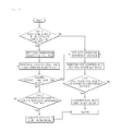
- FIG. 2 is a flowchart illustrating a control method of an electronic waste gate actuator according to one form of the present disclosure.
- FIG. 1 is a view showing the connection of a general electronic waste gate actuator, a waste gate valve, and a rod.
- the waste gate valve 30 which is open or closed by the electronic waste gate actuator 10 , is connected to the electronic waste gate actuator 10 through the rod 20 .
- the rod 20 When the operation mode of an engine corresponds to hot operation, the rod 20 is expanded compared to cold operation, due to heat. In this case, the voltage of the electronic waste gate actuator 10 is lower than that at the cold operation.
- the rod 20 contracts at cold start and at cold operation, compared to the hot operation.
- the voltage exceeds a reference voltage range that is learned at the hot operation. Accordingly, the warning light of a turbocharger may be lit and poor acceleration may be experienced in the vehicle.
- the present disclosure classifies the operation mode of an engine into cold operation and hot operation, and performs a learning step and controls an electronic waste gate actuator 10 according to the classified operation mode, thus reducing an error in signaling the warning light of a turbocharger, and improving vehicle acceleration performance by improving the performance of the turbocharger.
- FIG. 2 is a flowchart illustrating a control method of an electronic waste gate actuator according to one form of the present disclosure.
- the control method of an electronic waste gate actuator includes an operation condition determination step. Also, according to the operation condition of an engine, the control method includes a cold control step and a hot control step.
- the operation condition determination step measures the soak time of an engine and initial temperature of coolant when starting the engine, and determines the engine is in either a cold operation or hot operation by comparing the soak time and the coolant temperature with a reference soak time and reference coolant temperature, which are predetermined by an electronic control system (ECU).
- ECU electronice control system
- the reference soak time is 6 hours, and the reference coolant temperature is 20° C. If the engine soak time is longer than 6 hours for which the engine may be sufficiently cooled and the measured initial temperature of the coolant is lower than 20° C., the engine is in cold operation. If not, it is determined that the engine is in hot operation.
- the cold control step is performed.
- the cold control step sets cold operation reference voltage in the ECU, and performs cold control of the electronic waste gate actuator 10 depending on the reference voltage.
- cold operation learning is performed.
- the cold operation learning applies cold operation learning data, in which voltage information according to the location of the electronic waste gate actuator 10 is collected, to the cold operation reference voltage.
- the hot control step sets hot operation reference voltage in the ECU, and performs hot control of the electronic waste gate actuator.
- hot operation learning is performed, and the hot operation learning collects the hot operation learning data using the same method of the cold control step and applies the data to the hot operation reference voltage.
- the control method of an electronic waste gate actuator according to one form of the present disclosure further includes a cold limp-home conversion step and a hot limp-home conversion step.
- the operation voltage of the electronic waste gate actuator 10 is measured in real time.
- the cold operation voltage collected at the cold control step is compared with the cold operation reference voltage
- the hot operation voltage collected at the hot control step is compared with the hot operation reference voltage, whereby whether abnormal operation occurs is determined.
- the cold operation voltage and the hot operation voltage are respectively greater than the cold operation reference voltage and the hot operation reference voltage, it is determined that an error has occurred in a turbocharger including the electronic waste gate actuator 10 , and the vehicle is changed to a limp-home mode to minimize additional damage to the vehicle.
- the cold limp-home conversion step and the hot limp-home conversion step enable reduced driving by limiting the revolutions per minute (RPM) of the engine to be equal to or less than 2000 RPM.
- RPM revolutions per minute
- the hot control step is carried out.
- the coolant temperature is measured in real time and compared with the reference coolant temperature. Accordingly, when the coolant temperature is greater than the reference coolant temperature, which is 20° C., it is determined that the operation condition is changed from cold operation to hot operation due to the increase in temperature, and the cold control step is converted into the hot control step.
- the reference voltage is categorized into cold operation reference voltage and hot operation reference voltage.
- the electronic waste gate actuator 10 is controlled by the cold operation reference voltage and hot operation reference voltage, whereby errors in signaling the warning light of a turbocharger and poor acceleration in a vehicle may be solved.
Landscapes
- Engineering & Computer Science (AREA)
- Chemical & Material Sciences (AREA)
- Combustion & Propulsion (AREA)
- Mechanical Engineering (AREA)
- General Engineering & Computer Science (AREA)
- Supercharger (AREA)
Abstract
Description
Claims (7)
Applications Claiming Priority (2)
| Application Number | Priority Date | Filing Date | Title |
|---|---|---|---|
| KR1020150096367A KR101745105B1 (en) | 2015-07-07 | 2015-07-07 | Control method of electrical waste gate actuator |
| KR10-2015-0096367 | 2015-07-07 |
Publications (2)
| Publication Number | Publication Date |
|---|---|
| US20170009692A1 US20170009692A1 (en) | 2017-01-12 |
| US9816453B2 true US9816453B2 (en) | 2017-11-14 |
Family
ID=57583783
Family Applications (1)
| Application Number | Title | Priority Date | Filing Date |
|---|---|---|---|
| US14/936,297 Expired - Fee Related US9816453B2 (en) | 2015-07-07 | 2015-11-09 | Control method of electronic waste gate actuator |
Country Status (4)
| Country | Link |
|---|---|
| US (1) | US9816453B2 (en) |
| KR (1) | KR101745105B1 (en) |
| CN (1) | CN106337729B (en) |
| DE (1) | DE102015222327B4 (en) |
Citations (14)
| Publication number | Priority date | Publication date | Assignee | Title |
|---|---|---|---|---|
| US4697421A (en) | 1983-10-13 | 1987-10-06 | Honda Giken Kogyo Kabushiki Kaisha | Supercharging pressure control system for an internal combustion engine with a tubocharger and method of operation |
| JPH0874588A (en) | 1994-09-02 | 1996-03-19 | Daihatsu Motor Co Ltd | Supercharging control method |
| JP2002332880A (en) | 2001-05-08 | 2002-11-22 | Suzuki Motor Corp | Supercharging pressure control device for internal combustion engine |
| KR20030047305A (en) | 2001-12-10 | 2003-06-18 | 현대자동차주식회사 | Turbo-charger system and control method thereof |
| JP2003214246A (en) | 2002-01-18 | 2003-07-30 | Denso Corp | Automotive control device |
| JP2006188989A (en) | 2005-01-06 | 2006-07-20 | Toyota Motor Corp | Supercharging system for internal combustion engines |
| KR20100023582A (en) | 2008-08-22 | 2010-03-04 | 현대자동차주식회사 | Method for controlling vgt solenoid valve |
| KR20120054410A (en) | 2010-11-19 | 2012-05-30 | 주식회사 만도 | Electric waste gate actuator for turbochager |
| KR20120068417A (en) | 2010-12-17 | 2012-06-27 | 콘티넨탈 오토모티브 시스템 주식회사 | Method and apparatus for controlling engine of car |
| JP2012180793A (en) | 2011-03-02 | 2012-09-20 | Toyota Motor Corp | Control device of internal combustion engine |
| US20120240571A1 (en) * | 2010-12-07 | 2012-09-27 | Toyota Jidosha Kabushiki Kaisha | Control device for internal combustion engine |
| US20140047832A1 (en) * | 2012-08-17 | 2014-02-20 | Ford Global Technologies, Llc | Turbocharger system having an air-cooled wastegate actuator |
| US20140341703A1 (en) * | 2013-05-16 | 2014-11-20 | Ford Global Technologies, Llc | Method and system for operating an engine turbocharger waste gate |
| US20150101581A1 (en) * | 2013-10-14 | 2015-04-16 | GM Global Technology Operations LLC | Method of controlling the pressure of a turbocharger |
Family Cites Families (2)
| Publication number | Priority date | Publication date | Assignee | Title |
|---|---|---|---|---|
| KR101254232B1 (en) * | 2010-12-07 | 2013-04-18 | 주식회사 만도 | Electric waste gate actuator for turbochager |
| US9169771B2 (en) * | 2013-09-20 | 2015-10-27 | Ford Global Technologies, Llc | Wastegate valve position correction |
-
2015
- 2015-07-07 KR KR1020150096367A patent/KR101745105B1/en not_active Expired - Fee Related
- 2015-11-09 US US14/936,297 patent/US9816453B2/en not_active Expired - Fee Related
- 2015-11-11 CN CN201510766032.7A patent/CN106337729B/en not_active Expired - Fee Related
- 2015-11-12 DE DE102015222327.2A patent/DE102015222327B4/en not_active Expired - Fee Related
Patent Citations (14)
| Publication number | Priority date | Publication date | Assignee | Title |
|---|---|---|---|---|
| US4697421A (en) | 1983-10-13 | 1987-10-06 | Honda Giken Kogyo Kabushiki Kaisha | Supercharging pressure control system for an internal combustion engine with a tubocharger and method of operation |
| JPH0874588A (en) | 1994-09-02 | 1996-03-19 | Daihatsu Motor Co Ltd | Supercharging control method |
| JP2002332880A (en) | 2001-05-08 | 2002-11-22 | Suzuki Motor Corp | Supercharging pressure control device for internal combustion engine |
| KR20030047305A (en) | 2001-12-10 | 2003-06-18 | 현대자동차주식회사 | Turbo-charger system and control method thereof |
| JP2003214246A (en) | 2002-01-18 | 2003-07-30 | Denso Corp | Automotive control device |
| JP2006188989A (en) | 2005-01-06 | 2006-07-20 | Toyota Motor Corp | Supercharging system for internal combustion engines |
| KR20100023582A (en) | 2008-08-22 | 2010-03-04 | 현대자동차주식회사 | Method for controlling vgt solenoid valve |
| KR20120054410A (en) | 2010-11-19 | 2012-05-30 | 주식회사 만도 | Electric waste gate actuator for turbochager |
| US20120240571A1 (en) * | 2010-12-07 | 2012-09-27 | Toyota Jidosha Kabushiki Kaisha | Control device for internal combustion engine |
| KR20120068417A (en) | 2010-12-17 | 2012-06-27 | 콘티넨탈 오토모티브 시스템 주식회사 | Method and apparatus for controlling engine of car |
| JP2012180793A (en) | 2011-03-02 | 2012-09-20 | Toyota Motor Corp | Control device of internal combustion engine |
| US20140047832A1 (en) * | 2012-08-17 | 2014-02-20 | Ford Global Technologies, Llc | Turbocharger system having an air-cooled wastegate actuator |
| US20140341703A1 (en) * | 2013-05-16 | 2014-11-20 | Ford Global Technologies, Llc | Method and system for operating an engine turbocharger waste gate |
| US20150101581A1 (en) * | 2013-10-14 | 2015-04-16 | GM Global Technology Operations LLC | Method of controlling the pressure of a turbocharger |
Also Published As
| Publication number | Publication date |
|---|---|
| KR101745105B1 (en) | 2017-06-21 |
| US20170009692A1 (en) | 2017-01-12 |
| DE102015222327A1 (en) | 2017-01-12 |
| KR20170006314A (en) | 2017-01-18 |
| CN106337729A (en) | 2017-01-18 |
| CN106337729B (en) | 2019-11-12 |
| DE102015222327B4 (en) | 2021-06-10 |
Similar Documents
| Publication | Publication Date | Title |
|---|---|---|
| EP2165065B1 (en) | Fuel injection control apparatus and fuel injection control method | |
| JP6123707B2 (en) | Control device for internal combustion engine | |
| US20150240707A1 (en) | Wastegate valve seat position determination | |
| US20170159586A1 (en) | Abnormality diagnosis device and abnormality diagnosis method for supercharger | |
| JP5847857B2 (en) | Reference position learning device for a valve of an internal combustion engine | |
| US20110146634A1 (en) | Supercharger control device for an internal combustion engine | |
| CN106560607B (en) | Control method of supercharger | |
| CN112096513A (en) | Electric waste gas bypass valve control method and device, vehicle and storage medium | |
| CN100538057C (en) | Learning-oriented exhaust gas recirculation valve position control | |
| Lüddecke et al. | On mixed flow turbines for automotive turbocharger applications | |
| US8991243B2 (en) | Method and device for diagnosing an actuator for an exhaust-gas-driven supercharger | |
| CN111412062B (en) | A method for diagnosing rationality of engine coolant temperature sensor signal | |
| JP5063388B2 (en) | Supercharging pressure control system | |
| US9816453B2 (en) | Control method of electronic waste gate actuator | |
| CN106246392B (en) | Control device for internal combustion engine | |
| JP2009007940A (en) | Cylinder-charged air quantity calculating apparatus for internal combustion engine | |
| CN106150714B (en) | Control device and control method for internal combustion engine | |
| JP6450015B2 (en) | Control device | |
| CN116816487B (en) | Engine electronic main water pump control method, device and storage medium | |
| US20180094565A1 (en) | Method and device for determining the load condition of an exhaust gas particulate filter | |
| Galindo et al. | Assessment of a sequentially turbocharged diesel engine on real-life driving cycles | |
| US10995684B1 (en) | Smart actuator learn command process | |
| US10982609B2 (en) | Method and device for controlling an internal combustion engine supercharged by an exhaust-gas turbocharger | |
| JP4224697B2 (en) | Optimal ignition timing setting method and optimal ignition timing setting device for internal combustion engine | |
| JP4934084B2 (en) | Warm-up acceleration control device for internal combustion engine |
Legal Events
| Date | Code | Title | Description |
|---|---|---|---|
| AS | Assignment |
Owner name: KIA MOTORS CORPORATION, KOREA, REPUBLIC OF Free format text: ASSIGNMENT OF ASSIGNORS INTEREST;ASSIGNORS:KIM, YOUNG MIN;KIM, HYUN;KIM, DEOK RYOL;REEL/FRAME:037007/0862 Effective date: 20151026 Owner name: HYUNDAI MOTOR COMPANY, KOREA, REPUBLIC OF Free format text: ASSIGNMENT OF ASSIGNORS INTEREST;ASSIGNORS:KIM, YOUNG MIN;KIM, HYUN;KIM, DEOK RYOL;REEL/FRAME:037007/0862 Effective date: 20151026 |
|
| STCF | Information on status: patent grant |
Free format text: PATENTED CASE |
|
| MAFP | Maintenance fee payment |
Free format text: PAYMENT OF MAINTENANCE FEE, 4TH YEAR, LARGE ENTITY (ORIGINAL EVENT CODE: M1551); ENTITY STATUS OF PATENT OWNER: LARGE ENTITY Year of fee payment: 4 |
|
| FEPP | Fee payment procedure |
Free format text: MAINTENANCE FEE REMINDER MAILED (ORIGINAL EVENT CODE: REM.); ENTITY STATUS OF PATENT OWNER: LARGE ENTITY |
|
| LAPS | Lapse for failure to pay maintenance fees |
Free format text: PATENT EXPIRED FOR FAILURE TO PAY MAINTENANCE FEES (ORIGINAL EVENT CODE: EXP.); ENTITY STATUS OF PATENT OWNER: LARGE ENTITY |
|
| STCH | Information on status: patent discontinuation |
Free format text: PATENT EXPIRED DUE TO NONPAYMENT OF MAINTENANCE FEES UNDER 37 CFR 1.362 |
|
| FP | Lapsed due to failure to pay maintenance fee |
Effective date: 20251114 |