US9815128B1 - Extraction tongs with replaceable jaw tips - Google Patents
Extraction tongs with replaceable jaw tips Download PDFInfo
- Publication number
- US9815128B1 US9815128B1 US15/374,046 US201615374046A US9815128B1 US 9815128 B1 US9815128 B1 US 9815128B1 US 201615374046 A US201615374046 A US 201615374046A US 9815128 B1 US9815128 B1 US 9815128B1
- Authority
- US
- United States
- Prior art keywords
- jaw tip
- jaw
- extension
- tong
- slot
- Prior art date
- Legal status (The legal status is an assumption and is not a legal conclusion. Google has not performed a legal analysis and makes no representation as to the accuracy of the status listed.)
- Active
Links
Images


Classifications
-
- B—PERFORMING OPERATIONS; TRANSPORTING
- B25—HAND TOOLS; PORTABLE POWER-DRIVEN TOOLS; MANIPULATORS
- B25J—MANIPULATORS; CHAMBERS PROVIDED WITH MANIPULATION DEVICES
- B25J15/00—Gripping heads and other end effectors
- B25J15/0033—Gripping heads and other end effectors with gripping surfaces having special shapes
-
- B—PERFORMING OPERATIONS; TRANSPORTING
- B23—MACHINE TOOLS; METAL-WORKING NOT OTHERWISE PROVIDED FOR
- B23D—PLANING; SLOTTING; SHEARING; BROACHING; SAWING; FILING; SCRAPING; LIKE OPERATIONS FOR WORKING METAL BY REMOVING MATERIAL, NOT OTHERWISE PROVIDED FOR
- B23D35/00—Tools for shearing machines or shearing devices; Holders or chucks for shearing tools
- B23D35/001—Tools for shearing machines or shearing devices; Holders or chucks for shearing tools cutting members
-
- B—PERFORMING OPERATIONS; TRANSPORTING
- B23—MACHINE TOOLS; METAL-WORKING NOT OTHERWISE PROVIDED FOR
- B23D—PLANING; SLOTTING; SHEARING; BROACHING; SAWING; FILING; SCRAPING; LIKE OPERATIONS FOR WORKING METAL BY REMOVING MATERIAL, NOT OTHERWISE PROVIDED FOR
- B23D31/00—Shearing machines or shearing devices covered by none or more than one of the groups B23D15/00 - B23D29/00; Combinations of shearing machines
- B23D31/008—Cutting-up scrap
-
- B—PERFORMING OPERATIONS; TRANSPORTING
- B23—MACHINE TOOLS; METAL-WORKING NOT OTHERWISE PROVIDED FOR
- B23D—PLANING; SLOTTING; SHEARING; BROACHING; SAWING; FILING; SCRAPING; LIKE OPERATIONS FOR WORKING METAL BY REMOVING MATERIAL, NOT OTHERWISE PROVIDED FOR
- B23D35/00—Tools for shearing machines or shearing devices; Holders or chucks for shearing tools
- B23D35/002—Means for mounting the cutting members
-
- B—PERFORMING OPERATIONS; TRANSPORTING
- B25—HAND TOOLS; PORTABLE POWER-DRIVEN TOOLS; MANIPULATORS
- B25J—MANIPULATORS; CHAMBERS PROVIDED WITH MANIPULATION DEVICES
- B25J15/00—Gripping heads and other end effectors
- B25J15/08—Gripping heads and other end effectors having finger members
-
- B—PERFORMING OPERATIONS; TRANSPORTING
- B66—HOISTING; LIFTING; HAULING
- B66C—CRANES; LOAD-ENGAGING ELEMENTS OR DEVICES FOR CRANES, CAPSTANS, WINCHES, OR TACKLES
- B66C3/00—Load-engaging elements or devices attached to lifting or lowering gear of cranes or adapted for connection therewith and intended primarily for transmitting lifting forces to loose materials; Grabs
-
- E—FIXED CONSTRUCTIONS
- E02—HYDRAULIC ENGINEERING; FOUNDATIONS; SOIL SHIFTING
- E02F—DREDGING; SOIL-SHIFTING
- E02F3/00—Dredgers; Soil-shifting machines
- E02F3/04—Dredgers; Soil-shifting machines mechanically-driven
- E02F3/96—Dredgers; Soil-shifting machines mechanically-driven with arrangements for alternate or simultaneous use of different digging elements
- E02F3/965—Dredgers; Soil-shifting machines mechanically-driven with arrangements for alternate or simultaneous use of different digging elements of metal-cutting or concrete-crushing implements
-
- E—FIXED CONSTRUCTIONS
- E02—HYDRAULIC ENGINEERING; FOUNDATIONS; SOIL SHIFTING
- E02F—DREDGING; SOIL-SHIFTING
- E02F9/00—Component parts of dredgers or soil-shifting machines, not restricted to one of the kinds covered by groups E02F3/00 - E02F7/00
- E02F9/28—Small metalwork for digging elements, e.g. teeth scraper bits
- E02F9/2808—Teeth
- E02F9/2816—Mountings therefor
-
- E—FIXED CONSTRUCTIONS
- E02—HYDRAULIC ENGINEERING; FOUNDATIONS; SOIL SHIFTING
- E02F—DREDGING; SOIL-SHIFTING
- E02F9/00—Component parts of dredgers or soil-shifting machines, not restricted to one of the kinds covered by groups E02F3/00 - E02F7/00
- E02F9/28—Small metalwork for digging elements, e.g. teeth scraper bits
- E02F9/2808—Teeth
- E02F9/2858—Teeth characterised by shape
Definitions
- the present invention relates generally to recycling and more specifically to extraction tongs with replaceable jaw tips, which includes jaw tips with mating gripping projections.
- Extraction tongs are a gripping portion of excavator grapples.
- the excavator grapple may be used to extract objects from an engine bay of a salvaged vehicle.
- the jaw tips at an end of the extraction tongs will wear after a period of time.
- the jaw tips need to be replaceable, but must also be fully secured to the extraction tong.
- U.S. Pat. No. 5,474,242 to Rafn discloses demolition tools with jaws having replaceable working surfaces.
- Patent no. 2013/0068079 to Kimura et al. discloses a demolition cutter.
- U.S. Pat. No. 8,650,759 to Johnson et al. discloses a metal demolition shears with indexable, integrated wear plate/piercing tip.
- U.S. Pat. No. 9,132,490 to Ramun discloses an interlocking tip for demolition and construction equipment.
- Pat. No. D740861 to Aerts discloses a jaw tip.
- the present invention provides extraction tongs with replaceable jaw tips, which include jaw tips with mating gripping projections.
- Each extraction tong includes a tapered body with a plurality of inward extending teeth.
- a thickness of the extraction tong is reduced at a bottom thereof. The thickness is reduced on opposing sides of the extraction tong to form a jaw tip extension.
- a substantially triangular projection extends outward from opposing sides of the jaw tip extension.
- a plurality of extension holes are formed through the thickness of the jaw tip extension.
- Each jaw tip includes a tong slot, which is sized to receive the thickness of the jaw tip extension.
- a substantially triangular slot is formed in opposing walls of the tong slot to receive the two substantially triangular projections.
- a plurality of counterbore holes are formed in opposing sides of the jaw tip.
- the plurality of counterbore holes are concentric with the plurality of extension holes formed through the thickness of the jaw tip extension.
- a first lengthwise projection is formed on a gripping surface of the first jaw tip.
- a pair of second lengthwise projections are formed on a gripping surface of the second jaw tip. The first lengthwise projection fits between the pair of second lengthwise projections.
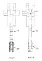
- FIG. 1 is a perspective view of an extraction tong in accordance with the present invention.
- FIG. 2 is a perspective view of a first jaw tip in accordance with the present invention.
- FIG. 3 is a perspective view of a second jaw tip in accordance with the present invention.
- FIG. 4 is a rear perspective view of a first or second jaw tip in accordance with the present invention.
- FIG. 4 a is a rear perspective view of a first or second jaw tip position at a different perspective angle than FIG. 4 in accordance with the present invention.
- FIG. 5 is a perspective view of a first jaw tip attached to an extraction tong in accordance with the present invention.
- FIG. 6 is a rear perspective view of a first or second jaw tip attached to an extraction tong in accordance with the present invention.
- FIG. 7 is a perspective view of a second jaw tip attached to an extraction tong in accordance with the present invention.
- FIG. 8 is a side view of a first or second jaw tip attached to an extraction tong in accordance with the present invention.
- FIG. 9 is a front view of a first jaw tip attached to an extraction tong in accordance with the present invention.
- FIG. 10 is a rear view of a first jaw tip attached to an extraction tong in accordance with the present invention.
- FIG. 11 is a front view of a second jaw tip attached to an extraction tong in accordance with the present invention.
- FIG. 12 is a rear view of a second jaw tip attached to an extraction tong in accordance with the present invention.
- each extraction tong 10 includes a tapered body 14 with a plurality of teeth 16 formed on an inward surface thereof.
- a thickness of the extraction tong 10 is reduced at a bottom thereof. The thickness is reduced on opposing sides of the extraction tong 10 to form a jaw tip extension 18 .
- a planar contact surface 19 is formed on a front of the jaw tip extension 18 .
- a substantially triangular projection 20 extends outward from opposing sides of the jaw tip extension 18 .
- a top edge 21 of the substantially triangular projection 20 is not parallel with a top edge 23 of the jaw tip extension 18 .
- a distance between the top edge 21 and the top edge 23 form a wedge slot 15 .
- a dimension “A” at an entrance of the wedge slot 15 edge 23 is greater than a dimension “B” at an end thereof.
- a plurality of extension holes 22 are formed through the thickness of the jaw tip extension 18 .
- the first jaw tip 12 includes a substantially triangular shaped body 13 and a first tong slot 24 formed in a rear of the first jaw tip 12 to receive the thickness of the jaw tip extension 18 .
- a second jaw tip 26 includes a substantially triangular shaped body 27 and a second tong slot 28 formed in a rear of the second jaw tip 26 to receive the thickness of the jaw tip extension 18 .
- a substantially triangular slot 30 is formed in opposing walls of the first and second tong slots 24 , 28 to receive the two substantially triangular projections 20 .
- the substantially triangular slot 30 includes a top edge 31 .
- a top edge 33 of the first and second jaw tips 12 , 26 is not parallel to top edge 31 of the substantially triangular slot 30 .
- the top edge 31 and the top edge 33 form a wedge projection 17 .
- the wedge projection 17 forms a wedge fit with the wedge slot 15 to retain the jaw tips 12 , 26 on the jaw tip extension 18 .
- a corner relief 25 is preferably formed on a front of the substantially triangular projection 20 to provide clearance for a corner of the substantially triangular slot 30 .
- a plurality of counterbore holes 32 are formed in opposing sides of the first and second jaw tips 12 , 26 .
- the plurality of counterbore holes 32 are concentric with the plurality of extension holes 22 .
- a plurality of bolts 35 and a plurality of hex nuts 37 are used to secure the first and second jaw tips 12 , 26 to the extraction tong 10 .
- the counterbore holes 32 allow the plurality of bolts 35 and hex nuts 37 to be substantially flush with the opposing sides of the first and second jaw tips 12 , 26 .
- a first lengthwise projection 34 is formed on a gripping surface 36 of the first jaw tip 12 .
- a pair of second lengthwise projections 38 are formed on a gripping surface 40 of a second jaw tip 26 .
- the first lengthwise projection 34 fits between the pair of second lengthwise projections 38 .
- the first and second gripping surfaces 38 , 40 are preferably flat or planar.
- a first inner planar contact surface 42 is formed on a bottom of the first tong slot 24 .
- a second inner planar contact surface 44 is formed on a bottom of the second tong slot 28 .
- the first and second inner planar contact surfaces 42 , 44 make physical contact with the planar contact surface 19 of the jaw tip extension 18 , when the first and second jaw tips 12 , 26 are attached to the jaw tip extension 18 .
Landscapes
- Engineering & Computer Science (AREA)
- Mechanical Engineering (AREA)
- Structural Engineering (AREA)
- Mining & Mineral Resources (AREA)
- Civil Engineering (AREA)
- General Engineering & Computer Science (AREA)
- Robotics (AREA)
- Table Equipment (AREA)
Abstract
Description
Claims (19)
Priority Applications (1)
| Application Number | Priority Date | Filing Date | Title |
|---|---|---|---|
| US15/374,046 US9815128B1 (en) | 2016-12-09 | 2016-12-09 | Extraction tongs with replaceable jaw tips |
Applications Claiming Priority (1)
| Application Number | Priority Date | Filing Date | Title |
|---|---|---|---|
| US15/374,046 US9815128B1 (en) | 2016-12-09 | 2016-12-09 | Extraction tongs with replaceable jaw tips |
Publications (1)
| Publication Number | Publication Date |
|---|---|
| US9815128B1 true US9815128B1 (en) | 2017-11-14 |
Family
ID=60256376
Family Applications (1)
| Application Number | Title | Priority Date | Filing Date |
|---|---|---|---|
| US15/374,046 Active US9815128B1 (en) | 2016-12-09 | 2016-12-09 | Extraction tongs with replaceable jaw tips |
Country Status (1)
| Country | Link |
|---|---|
| US (1) | US9815128B1 (en) |
Cited By (5)
| Publication number | Priority date | Publication date | Assignee | Title |
|---|---|---|---|---|
| USD952005S1 (en) * | 2020-09-29 | 2022-05-17 | Gsl Innovations Inc. | Jaw member for tree removal device |
| USD954763S1 (en) * | 2020-01-24 | 2022-06-14 | Nye Manufacturing Ltd. | Grapple shear attachment |
| US11529634B2 (en) * | 2016-09-15 | 2022-12-20 | Caterpillar Work Tools B.V. | Replaceable work part for a demolition tool |
| CN116018936A (en) * | 2023-03-02 | 2023-04-28 | 南京邮电大学 | A light-weight autonomous fruit-picking aerial robot with extendable end of manipulator |
| US20250178103A1 (en) * | 2023-11-30 | 2025-06-05 | Michael Richard Ramun | Jaw Set with Modular Platforms and Interchangeable Segments |
Citations (18)
| Publication number | Priority date | Publication date | Assignee | Title |
|---|---|---|---|---|
| US3063176A (en) * | 1960-10-27 | 1962-11-13 | Caterpillar Tractor Co | Replaceable ripper tip |
| US3623247A (en) * | 1970-01-26 | 1971-11-30 | Caterpillar Tractor Co | High strength digging tooth |
| US3959901A (en) * | 1975-06-30 | 1976-06-01 | Caterpillar Tractor Co. | High strength earth working penetration tooth |
| USD243843S (en) * | 1975-08-13 | 1977-03-29 | Edwards Gerald D | Tooth for power digger |
| US4542929A (en) * | 1983-09-01 | 1985-09-24 | Possinger Warren K | Articulating clam type grapple for a backhoe |
| US4776113A (en) * | 1987-10-27 | 1988-10-11 | Caterpillar Inc. | Corner guard system having a replaceable corner tooth |
| US4848013A (en) * | 1988-10-24 | 1989-07-18 | Caterpillar Inc. | Two pin fastening assembly with interconnecting and retaining means |
| US5474242A (en) | 1994-10-11 | 1995-12-12 | The Stanley Works | Demolition tools with jaws having replaceable working surfaces |
| US6276733B1 (en) * | 1998-06-30 | 2001-08-21 | Phd, Inc. | Jaw tips and jaw tip assemblies for parts grippers |
| US20050235498A1 (en) * | 2004-04-21 | 2005-10-27 | Allied Gator, Inc. | Tip for demolition and construction equipment |
| US20080086920A1 (en) * | 2005-05-24 | 2008-04-17 | Lim Young Ju | Bucket assembly for excavator |
| US20120299321A1 (en) * | 2011-05-24 | 2012-11-29 | Genesis Attachments, Llc | Orange peel grapple |
| US20130068079A1 (en) | 2010-06-01 | 2013-03-21 | Sehiro Kimura | Demolition cutter |
| US8650759B2 (en) | 2003-10-31 | 2014-02-18 | Stanley Black & Decker, Inc. | Metal demolition shears with indexable, integrated wear plate/piercing tip |
| US9132490B2 (en) | 2012-06-11 | 2015-09-15 | John R. Ramun | Interlocking tip for demolition and construction equipment |
| USD740861S1 (en) | 2014-07-30 | 2015-10-13 | Alex M. Aerts | Jaw tip |
| US20150308076A1 (en) * | 2014-04-25 | 2015-10-29 | Exodus Machines, Inc. | Demolition adjustable shimable shear tip |
| USD779565S1 (en) * | 2016-01-12 | 2017-02-21 | S.A.S. Of Luxemburg, Ltd. | Grapple jaws |
-
2016
- 2016-12-09 US US15/374,046 patent/US9815128B1/en active Active
Patent Citations (18)
| Publication number | Priority date | Publication date | Assignee | Title |
|---|---|---|---|---|
| US3063176A (en) * | 1960-10-27 | 1962-11-13 | Caterpillar Tractor Co | Replaceable ripper tip |
| US3623247A (en) * | 1970-01-26 | 1971-11-30 | Caterpillar Tractor Co | High strength digging tooth |
| US3959901A (en) * | 1975-06-30 | 1976-06-01 | Caterpillar Tractor Co. | High strength earth working penetration tooth |
| USD243843S (en) * | 1975-08-13 | 1977-03-29 | Edwards Gerald D | Tooth for power digger |
| US4542929A (en) * | 1983-09-01 | 1985-09-24 | Possinger Warren K | Articulating clam type grapple for a backhoe |
| US4776113A (en) * | 1987-10-27 | 1988-10-11 | Caterpillar Inc. | Corner guard system having a replaceable corner tooth |
| US4848013A (en) * | 1988-10-24 | 1989-07-18 | Caterpillar Inc. | Two pin fastening assembly with interconnecting and retaining means |
| US5474242A (en) | 1994-10-11 | 1995-12-12 | The Stanley Works | Demolition tools with jaws having replaceable working surfaces |
| US6276733B1 (en) * | 1998-06-30 | 2001-08-21 | Phd, Inc. | Jaw tips and jaw tip assemblies for parts grippers |
| US8650759B2 (en) | 2003-10-31 | 2014-02-18 | Stanley Black & Decker, Inc. | Metal demolition shears with indexable, integrated wear plate/piercing tip |
| US20050235498A1 (en) * | 2004-04-21 | 2005-10-27 | Allied Gator, Inc. | Tip for demolition and construction equipment |
| US20080086920A1 (en) * | 2005-05-24 | 2008-04-17 | Lim Young Ju | Bucket assembly for excavator |
| US20130068079A1 (en) | 2010-06-01 | 2013-03-21 | Sehiro Kimura | Demolition cutter |
| US20120299321A1 (en) * | 2011-05-24 | 2012-11-29 | Genesis Attachments, Llc | Orange peel grapple |
| US9132490B2 (en) | 2012-06-11 | 2015-09-15 | John R. Ramun | Interlocking tip for demolition and construction equipment |
| US20150308076A1 (en) * | 2014-04-25 | 2015-10-29 | Exodus Machines, Inc. | Demolition adjustable shimable shear tip |
| USD740861S1 (en) | 2014-07-30 | 2015-10-13 | Alex M. Aerts | Jaw tip |
| USD779565S1 (en) * | 2016-01-12 | 2017-02-21 | S.A.S. Of Luxemburg, Ltd. | Grapple jaws |
Cited By (5)
| Publication number | Priority date | Publication date | Assignee | Title |
|---|---|---|---|---|
| US11529634B2 (en) * | 2016-09-15 | 2022-12-20 | Caterpillar Work Tools B.V. | Replaceable work part for a demolition tool |
| USD954763S1 (en) * | 2020-01-24 | 2022-06-14 | Nye Manufacturing Ltd. | Grapple shear attachment |
| USD952005S1 (en) * | 2020-09-29 | 2022-05-17 | Gsl Innovations Inc. | Jaw member for tree removal device |
| CN116018936A (en) * | 2023-03-02 | 2023-04-28 | 南京邮电大学 | A light-weight autonomous fruit-picking aerial robot with extendable end of manipulator |
| US20250178103A1 (en) * | 2023-11-30 | 2025-06-05 | Michael Richard Ramun | Jaw Set with Modular Platforms and Interchangeable Segments |
Similar Documents
| Publication | Publication Date | Title |
|---|---|---|
| US9815128B1 (en) | Extraction tongs with replaceable jaw tips | |
| US2427651A (en) | Excavating tooth | |
| US2385395A (en) | Excavating tooth | |
| US11027399B2 (en) | Hand tool such as a wire stripper or combination pliers | |
| US10029315B2 (en) | Drill bit | |
| US6886229B1 (en) | Hinge pin remover tool | |
| US9874001B2 (en) | Wedge-based earth-working tooth adapter retention assembly | |
| US20110005086A1 (en) | Pliers as middle cutter or side cutter | |
| EP3121340B1 (en) | Replaceable tip for a demolition tool | |
| WO2015098646A1 (en) | Drill insert and indexable drill | |
| US10486952B2 (en) | Anti-slip head of pry tool | |
| CA2160399C (en) | Shingle removing tool | |
| US4007550A (en) | Replaceable corner tooth assembly | |
| US2874491A (en) | Bucket tooth assembly | |
| US1855971A (en) | Metal cutting tool | |
| CN110062832A (en) | The utensil tip assembly at the tip with belt wear indicator | |
| US2841896A (en) | Excavating tooth with replaceable point | |
| US1561647A (en) | Fireman's ax | |
| JP2013002151A (en) | Lateral pin extraction tool for working machine bucket, and lateral pin extraction tool set | |
| US2885801A (en) | Tooth structure for trenchers and the like | |
| EP3056612B1 (en) | Tooth block for a demolition tool | |
| US20250092645A1 (en) | Attachment of a wear member | |
| CN205636865U (en) | A removable tooth that digs for on mud bucket | |
| US20140264208A1 (en) | Multi-Purpose Hammer | |
| US2285386A (en) | Sheet metal working tool |
Legal Events
| Date | Code | Title | Description |
|---|---|---|---|
| AS | Assignment |
Owner name: S.A.S. OF LUXEMBURG, LTD., WISCONSIN Free format text: ASSIGNMENT OF ASSIGNORS INTEREST;ASSIGNOR:JENSEN, COLTEN D., MR.;REEL/FRAME:040699/0325 Effective date: 20161209 |
|
| STCF | Information on status: patent grant |
Free format text: PATENTED CASE |
|
| MAFP | Maintenance fee payment |
Free format text: PAYMENT OF MAINTENANCE FEE, 4TH YR, SMALL ENTITY (ORIGINAL EVENT CODE: M2551); ENTITY STATUS OF PATENT OWNER: SMALL ENTITY Year of fee payment: 4 |
|
| MAFP | Maintenance fee payment |
Free format text: PAYMENT OF MAINTENANCE FEE, 8TH YR, SMALL ENTITY (ORIGINAL EVENT CODE: M2552); ENTITY STATUS OF PATENT OWNER: SMALL ENTITY Year of fee payment: 8 |