US9815008B2 - Elastic component providing indication of proper installation - Google Patents
Elastic component providing indication of proper installation Download PDFInfo
- Publication number
- US9815008B2 US9815008B2 US15/589,854 US201715589854A US9815008B2 US 9815008 B2 US9815008 B2 US 9815008B2 US 201715589854 A US201715589854 A US 201715589854A US 9815008 B2 US9815008 B2 US 9815008B2
- Authority
- US
- United States
- Prior art keywords
- domed structure
- force
- indication
- indicating
- indication mechanism
- Prior art date
- Legal status (The legal status is an assumption and is not a legal conclusion. Google has not performed a legal analysis and makes no representation as to the accuracy of the status listed.)
- Active
Links
- 238000009434 installation Methods 0.000 title description 2
- 238000000034 method Methods 0.000 claims abstract description 29
- 230000007246 mechanism Effects 0.000 claims description 26
- 239000012530 fluid Substances 0.000 claims description 20
- 230000007423 decrease Effects 0.000 claims description 11
- 239000000463 material Substances 0.000 claims description 11
- 230000000452 restraining effect Effects 0.000 claims 6
- 230000013011 mating Effects 0.000 abstract description 2
- 239000003921 oil Substances 0.000 description 44
- 239000010705 motor oil Substances 0.000 description 23
- 238000001914 filtration Methods 0.000 description 8
- 230000008602 contraction Effects 0.000 description 4
- 239000007789 gas Substances 0.000 description 3
- 229910000831 Steel Inorganic materials 0.000 description 2
- 229910052782 aluminium Inorganic materials 0.000 description 2
- XAGFODPZIPBFFR-UHFFFAOYSA-N aluminium Chemical compound [Al] XAGFODPZIPBFFR-UHFFFAOYSA-N 0.000 description 2
- 239000007788 liquid Substances 0.000 description 2
- 229910052751 metal Inorganic materials 0.000 description 2
- 239000002184 metal Substances 0.000 description 2
- 238000007789 sealing Methods 0.000 description 2
- 239000010959 steel Substances 0.000 description 2
- 230000009286 beneficial effect Effects 0.000 description 1
- 229920002678 cellulose Polymers 0.000 description 1
- 239000001913 cellulose Substances 0.000 description 1
- 238000002485 combustion reaction Methods 0.000 description 1
- 239000003344 environmental pollutant Substances 0.000 description 1
- 239000004744 fabric Substances 0.000 description 1
- 239000000835 fiber Substances 0.000 description 1
- 235000003642 hunger Nutrition 0.000 description 1
- 239000012535 impurity Substances 0.000 description 1
- 238000002347 injection Methods 0.000 description 1
- 239000007924 injection Substances 0.000 description 1
- 230000033001 locomotion Effects 0.000 description 1
- 238000012423 maintenance Methods 0.000 description 1
- 239000000203 mixture Substances 0.000 description 1
- 230000004048 modification Effects 0.000 description 1
- 238000012986 modification Methods 0.000 description 1
- 238000013021 overheating Methods 0.000 description 1
- 239000000123 paper Substances 0.000 description 1
- 239000002245 particle Substances 0.000 description 1
- 230000000737 periodic effect Effects 0.000 description 1
- 231100000719 pollutant Toxicity 0.000 description 1
- 229920000728 polyester Polymers 0.000 description 1
- 239000011148 porous material Substances 0.000 description 1
- 230000037351 starvation Effects 0.000 description 1
- 230000000007 visual effect Effects 0.000 description 1
Images


Classifications
-
- B—PERFORMING OPERATIONS; TRANSPORTING
- B01—PHYSICAL OR CHEMICAL PROCESSES OR APPARATUS IN GENERAL
- B01D—SEPARATION
- B01D27/00—Cartridge filters of the throw-away type
- B01D27/08—Construction of the casing
-
- B—PERFORMING OPERATIONS; TRANSPORTING
- B01—PHYSICAL OR CHEMICAL PROCESSES OR APPARATUS IN GENERAL
- B01D—SEPARATION
- B01D35/00—Filtering devices having features not specifically covered by groups B01D24/00 - B01D33/00, or for applications not specifically covered by groups B01D24/00 - B01D33/00; Auxiliary devices for filtration; Filter housing constructions
- B01D35/14—Safety devices specially adapted for filtration; Devices for indicating clogging
- B01D35/143—Filter condition indicators
-
- B—PERFORMING OPERATIONS; TRANSPORTING
- B01—PHYSICAL OR CHEMICAL PROCESSES OR APPARATUS IN GENERAL
- B01D—SEPARATION
- B01D29/00—Filters with filtering elements stationary during filtration, e.g. pressure or suction filters, not covered by groups B01D24/00 - B01D27/00; Filtering elements therefor
- B01D29/96—Filters with filtering elements stationary during filtration, e.g. pressure or suction filters, not covered by groups B01D24/00 - B01D27/00; Filtering elements therefor in which the filtering elements are moved between filtering operations; Particular measures for removing or replacing the filtering elements; Transport systems for filters
-
- B—PERFORMING OPERATIONS; TRANSPORTING
- B01—PHYSICAL OR CHEMICAL PROCESSES OR APPARATUS IN GENERAL
- B01D—SEPARATION
- B01D35/00—Filtering devices having features not specifically covered by groups B01D24/00 - B01D33/00, or for applications not specifically covered by groups B01D24/00 - B01D33/00; Auxiliary devices for filtration; Filter housing constructions
- B01D35/005—Filters specially adapted for use in internal-combustion engine lubrication or fuel systems
-
- B—PERFORMING OPERATIONS; TRANSPORTING
- B01—PHYSICAL OR CHEMICAL PROCESSES OR APPARATUS IN GENERAL
- B01D—SEPARATION
- B01D35/00—Filtering devices having features not specifically covered by groups B01D24/00 - B01D33/00, or for applications not specifically covered by groups B01D24/00 - B01D33/00; Auxiliary devices for filtration; Filter housing constructions
- B01D35/14—Safety devices specially adapted for filtration; Devices for indicating clogging
-
- B—PERFORMING OPERATIONS; TRANSPORTING
- B01—PHYSICAL OR CHEMICAL PROCESSES OR APPARATUS IN GENERAL
- B01D—SEPARATION
- B01D35/00—Filtering devices having features not specifically covered by groups B01D24/00 - B01D33/00, or for applications not specifically covered by groups B01D24/00 - B01D33/00; Auxiliary devices for filtration; Filter housing constructions
- B01D35/30—Filter housing constructions
- B01D35/306—Filter mounting adapter
-
- F—MECHANICAL ENGINEERING; LIGHTING; HEATING; WEAPONS; BLASTING
- F01—MACHINES OR ENGINES IN GENERAL; ENGINE PLANTS IN GENERAL; STEAM ENGINES
- F01M—LUBRICATING OF MACHINES OR ENGINES IN GENERAL; LUBRICATING INTERNAL COMBUSTION ENGINES; CRANKCASE VENTILATING
- F01M11/00—Component parts, details or accessories, not provided for in, or of interest apart from, groups F01M1/00 - F01M9/00
- F01M11/03—Mounting or connecting of lubricant purifying means relative to the machine or engine; Details of lubricant purifying means
-
- G—PHYSICS
- G01—MEASURING; TESTING
- G01L—MEASURING FORCE, STRESS, TORQUE, WORK, MECHANICAL POWER, MECHANICAL EFFICIENCY, OR FLUID PRESSURE
- G01L3/00—Measuring torque, work, mechanical power, or mechanical efficiency, in general
-
- G—PHYSICS
- G01—MEASURING; TESTING
- G01L—MEASURING FORCE, STRESS, TORQUE, WORK, MECHANICAL POWER, MECHANICAL EFFICIENCY, OR FLUID PRESSURE
- G01L5/00—Apparatus for, or methods of, measuring force, work, mechanical power, or torque, specially adapted for specific purposes
- G01L5/24—Apparatus for, or methods of, measuring force, work, mechanical power, or torque, specially adapted for specific purposes for determining value of torque or twisting moment for tightening a nut or other member which is similarly stressed
-
- G—PHYSICS
- G01—MEASURING; TESTING
- G01L—MEASURING FORCE, STRESS, TORQUE, WORK, MECHANICAL POWER, MECHANICAL EFFICIENCY, OR FLUID PRESSURE
- G01L7/00—Measuring the steady or quasi-steady pressure of a fluid or a fluent solid material by mechanical or fluid pressure-sensitive elements
- G01L7/02—Measuring the steady or quasi-steady pressure of a fluid or a fluent solid material by mechanical or fluid pressure-sensitive elements in the form of elastically-deformable gauges
- G01L7/08—Measuring the steady or quasi-steady pressure of a fluid or a fluent solid material by mechanical or fluid pressure-sensitive elements in the form of elastically-deformable gauges of the flexible-diaphragm type
- G01L7/084—Measuring the steady or quasi-steady pressure of a fluid or a fluent solid material by mechanical or fluid pressure-sensitive elements in the form of elastically-deformable gauges of the flexible-diaphragm type with mechanical transmitting or indicating means
-
- B—PERFORMING OPERATIONS; TRANSPORTING
- B01—PHYSICAL OR CHEMICAL PROCESSES OR APPARATUS IN GENERAL
- B01D—SEPARATION
- B01D2201/00—Details relating to filtering apparatus
- B01D2201/24—Tools used for the removal of filters
-
- B—PERFORMING OPERATIONS; TRANSPORTING
- B01—PHYSICAL OR CHEMICAL PROCESSES OR APPARATUS IN GENERAL
- B01D—SEPARATION
- B01D2201/00—Details relating to filtering apparatus
- B01D2201/30—Filter housing constructions
- B01D2201/301—Details of removable closures, lids, caps, filter heads
-
- B—PERFORMING OPERATIONS; TRANSPORTING
- B01—PHYSICAL OR CHEMICAL PROCESSES OR APPARATUS IN GENERAL
- B01D—SEPARATION
- B01D2201/00—Details relating to filtering apparatus
- B01D2201/30—Filter housing constructions
- B01D2201/301—Details of removable closures, lids, caps, filter heads
- B01D2201/304—Seals or gaskets
-
- B—PERFORMING OPERATIONS; TRANSPORTING
- B01—PHYSICAL OR CHEMICAL PROCESSES OR APPARATUS IN GENERAL
- B01D—SEPARATION
- B01D2201/00—Details relating to filtering apparatus
- B01D2201/30—Filter housing constructions
- B01D2201/301—Details of removable closures, lids, caps, filter heads
- B01D2201/305—Snap, latch or clip connecting means
-
- B—PERFORMING OPERATIONS; TRANSPORTING
- B01—PHYSICAL OR CHEMICAL PROCESSES OR APPARATUS IN GENERAL
- B01D—SEPARATION
- B01D2201/00—Details relating to filtering apparatus
- B01D2201/40—Special measures for connecting different parts of the filter
-
- B—PERFORMING OPERATIONS; TRANSPORTING
- B01—PHYSICAL OR CHEMICAL PROCESSES OR APPARATUS IN GENERAL
- B01D—SEPARATION
- B01D2201/00—Details relating to filtering apparatus
- B01D2201/40—Special measures for connecting different parts of the filter
- B01D2201/4023—Means for connecting filter housings to supports
-
- B—PERFORMING OPERATIONS; TRANSPORTING
- B01—PHYSICAL OR CHEMICAL PROCESSES OR APPARATUS IN GENERAL
- B01D—SEPARATION
- B01D2201/00—Details relating to filtering apparatus
- B01D2201/40—Special measures for connecting different parts of the filter
- B01D2201/4076—Anti-rotational means
-
- B—PERFORMING OPERATIONS; TRANSPORTING
- B01—PHYSICAL OR CHEMICAL PROCESSES OR APPARATUS IN GENERAL
- B01D—SEPARATION
- B01D2201/00—Details relating to filtering apparatus
- B01D2201/40—Special measures for connecting different parts of the filter
- B01D2201/4084—Snap or Seeger ring connecting means
-
- B—PERFORMING OPERATIONS; TRANSPORTING
- B01—PHYSICAL OR CHEMICAL PROCESSES OR APPARATUS IN GENERAL
- B01D—SEPARATION
- B01D2201/00—Details relating to filtering apparatus
- B01D2201/40—Special measures for connecting different parts of the filter
- B01D2201/4092—Threaded sections, e.g. screw
-
- B—PERFORMING OPERATIONS; TRANSPORTING
- B01—PHYSICAL OR CHEMICAL PROCESSES OR APPARATUS IN GENERAL
- B01D—SEPARATION
- B01D35/00—Filtering devices having features not specifically covered by groups B01D24/00 - B01D33/00, or for applications not specifically covered by groups B01D24/00 - B01D33/00; Auxiliary devices for filtration; Filter housing constructions
- B01D35/30—Filter housing constructions
-
- F—MECHANICAL ENGINEERING; LIGHTING; HEATING; WEAPONS; BLASTING
- F01—MACHINES OR ENGINES IN GENERAL; ENGINE PLANTS IN GENERAL; STEAM ENGINES
- F01M—LUBRICATING OF MACHINES OR ENGINES IN GENERAL; LUBRICATING INTERNAL COMBUSTION ENGINES; CRANKCASE VENTILATING
- F01M11/00—Component parts, details or accessories, not provided for in, or of interest apart from, groups F01M1/00 - F01M9/00
- F01M11/03—Mounting or connecting of lubricant purifying means relative to the machine or engine; Details of lubricant purifying means
- F01M2011/031—Mounting or connecting of lubricant purifying means relative to the machine or engine; Details of lubricant purifying means characterised by mounting means
Definitions
- Oil filters play a central role in protecting the engine within all automotive vehicles.
- a filter ensures optimum oil supply, especially during cold starts when oil viscosity is at its greatest. Over time the engine oil circuit becomes contaminated by combustion residue, metal shavings and other particles.
- engine oil is pumped into the oil filter where it is then passed through a pleated filtering medium designed to remove impurities down to the micron level. Once the engine oil is filtered through the pleated filtering medium, it then flows back into the oil pump where it is then sent to the engine.
- Oil filters are intended to be changed periodically, as the pleated filtering medium accumulates particulate debris suspended in the engine oil over time due to normal usage.
- the method described herein consists of a diaphragm, or other surface, which has material elasticity and bi-stability. Materials engineered in this fashion and may bend and or emit a sound or vibration when a predetermined amount of torque or force is applied (hereafter, indication). This indication denotes the required torque has been applied signifying the widget is installed properly.
- the surface displaced by the torque being applied can be of different configurations. This surface may be convex, concave, flat with a central or distal portion shaped in the needed fashion to cause it to emit an indication that a predetermined torque has been applied.
- the mechanism by which the surface emitting the indication is referred to as snap-through buckling.
- torque wrenches like the click, electronic or mechatronic types, require recalibration as part of their periodic maintenance. Further, when not in use, some types require a certain amount of tension while in storage to preserve the calibration of their internal components.
- the application described herein demonstrates the usefulness of the method in a setting where tight or confined spaces make the use of a torque wrench very difficult. In this instance, we refer to the modification of oil filters, used in a myriad of motive applications, so that properly consistent installation can be achieved without requiring the use of torque measuring devices.
- FIG. 1 is a perspective view of an Oil Filter according to a system and method of the present disclosure.
- FIG. 2 is a vertical cross section of an Oil Filter showing the direction and flow of oil according to a system and method of present disclosure.
- FIG. 3 is a vertical cross section of an Oil Filter prior to being coupled to an Engine Block according to a system and method of present disclosure.
- FIG. 4 is a vertical cross section of an Oil Filter coupled to an Engine Block according to a system and method of present disclosure.
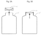
- FIG. 5A is a cross section of a bottle cap prior to being sealed onto a bottle according to a system and method of the present disclosure.
- FIG. 5B is a cross section of a bottle cap sealed onto a bottle according to a system and method of the present disclosure.
- FIG. 1 is a perspective view of an Oil Filter according to one aspect of the present invention.
- the center surface of Bottom Assembly 6 may have a female thread 20 for threading the Oil Filter 2 to Mounting Base 1 which female thread 20 is defined as an Outflow Hole 3 for passage of filtered engine oil back into the engine.
- the center surface 21 of Bottom Assembly 6 may displace pressure through mechanical hoop strength. Hoop strength is a mechanical property that may apply to flattened surfaces. It may appear on said surface in the form of a ring 22 . This ring contains and directs all applied force to the edges of the ring.
- Bi-stability allows the Bottom Assembly 6 to live in two stable “minima” states which are stable due to minimal pressure applied to the component. Bi-stable components also have a third state, called the “maximum” state. The maximum state lies in between the two minima states and is a direct result of the pressure applied while threading Oil Filter 2 onto Mounting Base 1 . When enough pressure is applied, Bottom Assembly 6 will go from one minima state, through the maximum state and regain stability in the other minima state.
- Oil Filter 2 consists of Filter Housing 5 , Bottom Assembly 6 , Sealing Ring 7 , Anti-Drain Valve (not shown), Pleated Filtering Medium 9 , Center Tube 10 , Outflow Hole 3 , Inflow Hole 4 , Bypass Valve 11 , and Relief Spring 12 .
- Filter Housing 5 may be may stamped, die cast or injection molded out of plastic, steel, aluminum or any rigid medium capable of enclosing the components within Filter Housing 5 .
- Filter Housing 5 may contain Pleated Filtering Medium 9 , which has two main functions; removing particulate residue from the engine oil and trapping particulate residue within the medium.
- Pleated Filtering Medium 9 may be a fabricated mixture of cellulose, cloth, paper, polyester fiber or any porous material that may possess the ability to trap and contain dirt and other residual material inside of it.
- FIG. 2 is a vertical section view of Oil Filter 2 showing the direction and flow of engine oil (shown as Arrow A, B and C) according to a system and method of present disclosure.
- direction of Arrow A may display how engine oil is pumped into Oil Filter 2 through Inflow Holes 4 .
- the engine oil enters into Oil Filter 2 through Inflow Holes 4 and then may pass through Pleated Filtering Medium 9 , as displayed in the direction of Arrow B.
- Filtered engine oil is then collected in Center Tube 10 and pumped back into the engine through Outflow Hole 3 , as displayed in the direction of Arrow C.
- Anti-Drain Valve (not shown) may be a one way check valve that allows filtered engine oil to flow from Oil Pump into Oil Filter 2 while the engine is running.
- Anti-Drain Valve may be open to allow for engine oil to flow when the engine is running. Anti-Drain Valve (not shown) may close to keep the engine and Oil Filter 2 passages lubricated when the engine is shut off.
- Bypass Valve 11 may be fitted beneath of Center Tube 10 within Oil Filter 2 .
- Bypass Valve 11 may be utilized to increase engine oil flow and engine oil pressure when the temperature of the engine oil falls below its standard operating temperature. In this aspect the viscosity of the engine oil may increase, which decreases the engine oil's ability to flow freely through the engine and Oil Filter 2 . If the engine oil falls below its standard operating temperature, Bypass Valve 11 may open and increase engine oil flow. As the engine and engine oil warms up, Bypass Valve 11 may close to regulate the engine oil pressure inside Oil Filter 2 . When Oil Filter 2 reaches its full capacity it may lose its ability to distribute engine oil through Pleated Filtering Medium 9 , in this aspect Bypass Valve 11 opens to regulate oil flow and oil pressure.
- FIG. 3 is a vertical section view of Oil Filter 2 in the expanded position according to a system and method of the present disclosure.
- Bottom Assembly 6 connected to the bottom of Oil Filter 2 , may be constructed of forged metal, steel, aluminum, plastic or any material that may easily be shaped into a hollow dome with bi-stability and material elasticity.
- Bottom Assembly 6 may be in the expanded position.
- Bottom Assembly 6 is expanded because there is no pressure or force being applied.
- Bottom Assembly 6 may replicate the motions exhibited in a diaphragm, expanding when no pressure is applied, and contracting when enough pressure is applied.
- Bottom Assembly 6 may contract, indicating Bottom Assembly 6 was properly connected to Mounting Base 1 .
- Oil Filter 2 may be threaded 23 on to Mounting Base 1 as shown in the direction of Arrow A.
- FIG. 4 is a section view of Oil Filter 2 in the contracted position according to a system and method of the present disclosure.
- Bottom Assembly 6 may be in a contracted position after being coupled to Mounting Base 1 . Once enough pressure is exerted on Bottom Assembly 6 through an appropriate torque value, Bottom Assembly 6 may contract, indicating Bottom Assembly 6 was properly connected to Mounting Base 1 .
- Bottom Assembly 6 When Bottom Assembly 6 is contracted, User (not shown) may be able to visually identify that Oil Filter 2 has been properly coupled to Mounting Base 1 .
- the contraction of Bottom Assembly 6 may also be identified by an audible sound and or a physical vibration known as snap-through buckling. This is a phenomenon that occurs on loading of a surface 21 , when the surface resistance suddenly decreases with increasing imposed deflection. In some instances, the drop-in load is accompanied by an audible “click” or “pop.”
- FIG. 5A and FIG. 5B are section views displaying a bottle cap being screwed onto a threaded bottle.
- the mechanisms involved in the expansion and contraction of Bottom Assembly 6 may be applied to objects other than oil filters, thus indicating an appropriate torque value was used to couple one object onto another object.
- Bottle Cap 14 could utilize the mechanisms explained herein to ensure the Bottle Cap 14 is tightly secured to the rim of a Bottle 15 .
- the Bottle Cap 14 may contract from the expanded position as a result of a force applied on the Bottle Cap 14 from the rim of the Bottle 15 as shown in the direction of Arrow B.
- an audible popping noise may be emitted and indicate to the user that an appropriate torque value has been applied to the Bottle 15 .
- the Bottle 15 could potentially leak fluid if the Bottle Cap 14 stays in the expanded position.
- a diaphragm on a tire rim may contract in the same fashion when being mounted on a vehicle.
- the constant force applied to a nut or bolt, locking a tire rim into place may cause the diaphragm contract, emit an audible pop and indicate to the user that an appropriate torque value has been applied and the tire is properly installed.
- This mechanism may be applied to any cylindrical container that requires a cylindrical lid.
- the pressure needed to activate the expansion or contraction of a component such as Bottom Assembly 6 may be caused by forces other than those manually applied by a user applying force or torque.
- some gases or fluids may create pressure within a bottle or container based on various factors such as but not limited to exposure to heat, cold, sunlight and additional liquids and gases.
- Bottle Cap 14 could indicate to a user that the liquid or gas within Bottle 15 is no longer edible, drinkable or usable based on the expansion or contraction of said bottle cap when sealed on a bottle.
Abstract
An apparatus having a bottom assembly with a fitting for interfacing to connect the bottom assembly to a second structure, having an elastic element that, when sufficient force is applied via the process of mating the bottom assembly to the second structure, and at an appropriate pressure value, passes from a first stable position, through a threshold, and to a second position, creating a tactile or audible indication that the apparatus has been properly installed.
Description
The present application claims priority to U.S. patent application Ser. No. 15/251,927, filed Aug. 30, 2016, to U.S. patent application Ser. No. 14/977,527, filed Dec. 21, 2015, now U.S. Pat. No. 9,463,401 B2, and, through that application, to U.S. patent application Ser. No. 14/271,721, filed May 7, 2014 (now abandoned), and those applications are incorporated by reference in their entirety.
Oil filters play a central role in protecting the engine within all automotive vehicles. A filter ensures optimum oil supply, especially during cold starts when oil viscosity is at its greatest. Over time the engine oil circuit becomes contaminated by combustion residue, metal shavings and other particles. To remove these pollutants engine oil is pumped into the oil filter where it is then passed through a pleated filtering medium designed to remove impurities down to the micron level. Once the engine oil is filtered through the pleated filtering medium, it then flows back into the oil pump where it is then sent to the engine. Oil filters are intended to be changed periodically, as the pleated filtering medium accumulates particulate debris suspended in the engine oil over time due to normal usage. While tightening an oil filter on a mounting base, one may be uncertain about the exact amount of torque required to securely tighten the oil filter to the mounting base of an engine block. Tightening it too much may cause damage to the oil filter, specifically the sealing ring, which may deform and allow pressurized oil to leak out. Not tightening it enough may also result in leaks, which may cause extensive damage to the engine due to oil starvation and subsequent overheating. Accordingly, it would be beneficial in the art if there were a tangible (e.g., audible) indication to the person installing the filter that the right amount of torque has been used and that the filter is properly secured and neither too tightly nor too loosely attached. Furthermore, visual, tactile, and/or audible indicators of sufficient levels of torque could be useful outside the context of an oil filter, such as in tire lug nuts or other nonautomotive applications such as bottle caps which change shape when the contents is spoiled.
The method described herein consists of a diaphragm, or other surface, which has material elasticity and bi-stability. Materials engineered in this fashion and may bend and or emit a sound or vibration when a predetermined amount of torque or force is applied (hereafter, indication). This indication denotes the required torque has been applied signifying the widget is installed properly. The surface displaced by the torque being applied can be of different configurations. This surface may be convex, concave, flat with a central or distal portion shaped in the needed fashion to cause it to emit an indication that a predetermined torque has been applied. The mechanism by which the surface emitting the indication is referred to as snap-through buckling. This is a phenomenon that occurs on loading of a panel, when the panel resistance suddenly decreases with increasing imposed deflection. In some instances, the drop-in load is accompanied by the release of a sound. Once the surface has been engineered to displace at a predetermined load, the end user, be it a manufacturer or DIY person at home, can be assured of consistent torque between two mating surfaces without having to use devices, which require proper use and calibration. Prior to this method, the most common tools for torqueing are torque wrenches, which are available in several types. Some of these types are slipper, beam, deflecting beam, click, electronic and mechatronic. Regardless of the type of torque wrench used they all need a certain amount of knowledge and proper use by the operator to yield a consistent and valid torque onto whatever is being installed. For instance, torque wrenches, like the click, electronic or mechatronic types, require recalibration as part of their periodic maintenance. Further, when not in use, some types require a certain amount of tension while in storage to preserve the calibration of their internal components. As one example of the use of the method, the application described herein demonstrates the usefulness of the method in a setting where tight or confined spaces make the use of a torque wrench very difficult. In this instance, we refer to the modification of oil filters, used in a myriad of motive applications, so that properly consistent installation can be achieved without requiring the use of torque measuring devices.
An oil filter having a mechanism for delivering a physical (e.g., audible or tactile) indication to the user that the filter is tightly secured and should not be further tightened, is disclosed. Turning now to the figures, where like numerals refer to like elements.
According to FIG. 2 , Oil Filter 2 consists of Filter Housing 5, Bottom Assembly 6, Sealing Ring 7, Anti-Drain Valve (not shown), Pleated Filtering Medium 9, Center Tube 10, Outflow Hole 3, Inflow Hole 4, Bypass Valve 11, and Relief Spring 12. Filter Housing 5 may be may stamped, die cast or injection molded out of plastic, steel, aluminum or any rigid medium capable of enclosing the components within Filter Housing 5. As shown in FIG. 2 , Filter Housing 5 may contain Pleated Filtering Medium 9, which has two main functions; removing particulate residue from the engine oil and trapping particulate residue within the medium. Pleated Filtering Medium 9 may be a fabricated mixture of cellulose, cloth, paper, polyester fiber or any porous material that may possess the ability to trap and contain dirt and other residual material inside of it.
Also shown in FIG. 2 , Bypass Valve 11 may be fitted beneath of Center Tube 10 within Oil Filter 2. Bypass Valve 11 may be utilized to increase engine oil flow and engine oil pressure when the temperature of the engine oil falls below its standard operating temperature. In this aspect the viscosity of the engine oil may increase, which decreases the engine oil's ability to flow freely through the engine and Oil Filter 2. If the engine oil falls below its standard operating temperature, Bypass Valve 11 may open and increase engine oil flow. As the engine and engine oil warms up, Bypass Valve 11 may close to regulate the engine oil pressure inside Oil Filter 2. When Oil Filter 2 reaches its full capacity it may lose its ability to distribute engine oil through Pleated Filtering Medium 9, in this aspect Bypass Valve 11 opens to regulate oil flow and oil pressure.
There are numerous applications for which the mechanisms described herein may be utilized so long as a constant force is applied to the component that expands and contracts. This constant force will cause the mechanism to reach a threshold, thus causing the material to go from an expanded to contracted position. In one non-limiting example, a diaphragm on a tire rim may contract in the same fashion when being mounted on a vehicle. The constant force applied to a nut or bolt, locking a tire rim into place may cause the diaphragm contract, emit an audible pop and indicate to the user that an appropriate torque value has been applied and the tire is properly installed. This mechanism may be applied to any cylindrical container that requires a cylindrical lid.
The pressure needed to activate the expansion or contraction of a component such as Bottom Assembly 6 may be caused by forces other than those manually applied by a user applying force or torque. For example, some gases or fluids may create pressure within a bottle or container based on various factors such as but not limited to exposure to heat, cold, sunlight and additional liquids and gases. For example, Bottle Cap 14 could indicate to a user that the liquid or gas within Bottle 15 is no longer edible, drinkable or usable based on the expansion or contraction of said bottle cap when sealed on a bottle.
Claims (30)
1. A force indication mechanism for a fluid connection between fluid devices, comprising:
a domed structure having
material elasticity;
a first stable position;
a second position;
a threshold between said positions; and
an outer ring;
said domed structure creating an indication that a desired force exists between said fluid devices while crossing said threshold; and
said outer ring mechanically restraining said domed structure.
2. The force indication mechanism of claim 1 ,
said desired force still existing when said domed structure is in said second position.
3. The force indication mechanism of claim 1 ,
said indication being accompanied by a sudden decrease in resistance of said domed structure to imposed deflection.
4. The force indication mechanism of claim 1 ,
each of said positions comprising a distinct shape assumed by said domed structure.
5. The force indication mechanism of claim 1 ,
said first stable position comprising a first shape assumed by said domed structure;
said second position comprising a second shape assumed by said domed structure;
said first and second shapes being distinct from one another.
6. The force indication mechanism of claim 5 ,
said first shape being substantially convex.
7. The force indication mechanism of claim 1 , further comprising at least one connection for connecting the force indication mechanism to one of said fluid devices.
8. The force indication mechanism of claim 1 ,
said ring mechanically restraining said domed structure by resisting axial compressive force immediately following said domed structure crossing said threshold.
9. The force indication mechanism of claim 8 ,
said indication being accompanied by a sudden decrease in resistance of said domed structure to imposed deflection; and
said desired force still existing when said domed structure is in said second position.
10. The force indication mechanism of claim 1 ,
said indication being audible.
11. A force indication mechanism for a fluid connection between fluid devices, comprising:
a domed structure having
material elasticity;
a first stable position;
a second position; and
a threshold between said positions;
said domed structure creating an indication that a desired force exists between said fluid devices while crossing said threshold;
wherein said fluid devices are a vehicle fluid filter and an engine mounting base; and
said domed structure creating an indication that a desired force exists between a seal of said vehicle fluid filter and the said engine mounting base.
12. The force indication mechanism of claim 11 ,
said desired force still existing when said domed structure is in said second position; and
said indication being audible.
13. The force indication mechanism of claim 11 ,
said indication being accompanied by a sudden decrease in resistance of said domed structure to imposed deflection.
14. The force indication mechanism of claim 11 ,
said domed structure further comprising an outer ring;
said ring mechanically restraining said domed structure by resisting axial compressive force immediately following said domed structure crossing said threshold.
15. The force indication mechanism of claim 14 ,
said indication being accompanied by a sudden decrease in resistance of said domed structure to imposed deflection; and
said desired force still existing when said domed structure is in said second position.
16. A method of indicating the force in a fluid connection between fluid devices, comprising:
operating a force indication mechanism comprising a domed structure,
said domed structure having
material elasticity;
a first stable position;
a second position;
a threshold between said positions; and
an outer ring;
said operating step comprising creating an indication that a desired force exists between said fluid devices;
said creating step comprising causing the domed structure to cross the threshold; and
said outer ring mechanically restraining said domed structure.
17. The method of indicating of claim 16 ,
said desired force still existing when said domed structure is in said second position.
18. The method of indicating of claim 16 ,
said operating step further comprising a sudden decrease in resistance of said domed structure to imposed deflection.
19. The method of indicating of claim 16 ,
each of said positions comprising a distinct shape assumed by said domed structure.
20. The method of indicating of claim 16 ,
said first stable position comprising a first shape assumed by said domed structure;
said second position comprising a second shape assumed by said domed structure;
said first and second shapes being distinct from one another.
21. The method of indicating of claim 20 ,
said first shape being substantially convex.
22. The method of indicating of claim 16 ,
said creating step further comprising applying sufficient force to said force indication mechanism to cause said domed structure to pass through said threshold between said first stable position and said second position.
23. The method of indicating of claim 16 ,
said ring mechanically restraining said domed structure by resisting axial compressive force immediately following said domed structure crossing said threshold.
24. The method of indicating of claim 23 ,
said operating step further comprising a sudden decrease in resistance of said domed structure to imposed deflection; and
said desired force still existing when said domed structure is in said second position.
25. The method of indicating of claim 16 ,
said operating step further comprising said indication being audible.
26. A method of indicating the force in a fluid connection between fluid devices, comprising:
operating a force indication mechanism comprising a domed structure,
said domed structure having
material elasticity;
a first stable position;
a second position; and
a threshold between said positions;
said operating step comprising creating an indication that a desired force exists between said fluid devices; and
said creating step comprising causing the domed structure to cross the threshold;
wherein said fluid devices are a vehicle fluid filter and an engine mounting base; and
said operating step further comprising said contacting said domed structure to said engine mounting base and to said vehicle oil filter.
27. The method of indicating of claim 26 ,
said desired force still existing when said domed structure is in said second position; and
said indication being audible.
28. The method of indicating of claim 26 ,
said operating step further comprising a sudden decrease in resistance of said domed structure to imposed deflection.
29. The method of indicating of claim 26 ,
said domed structure further comprising an outer ring;
said ring mechanically restraining said domed structure by resisting axial compressive force immediately following said domed structure crossing said threshold.
30. The method of indicating of claim 29 ,
said operating step further comprising a sudden decrease in resistance of said domed structure to imposed deflection; and
said desired force still existing when said domed structure is in said second position.
Priority Applications (1)
| Application Number | Priority Date | Filing Date | Title |
|---|---|---|---|
| US15/589,854 US9815008B2 (en) | 2014-05-07 | 2017-05-08 | Elastic component providing indication of proper installation |
Applications Claiming Priority (4)
| Application Number | Priority Date | Filing Date | Title |
|---|---|---|---|
| US14/271,721 US20150323401A1 (en) | 2014-05-07 | 2014-05-07 | Method for Installing an Apparatus to the Correct Torque Setting Without the Use of Torque Measuring Tools |
| US14/977,527 US9463401B2 (en) | 2014-05-07 | 2015-12-21 | Bi-stable component providing indication of proper installation |
| US15/251,927 US9643114B2 (en) | 2014-05-07 | 2016-08-30 | Elastic component providing indication of proper installation |
| US15/589,854 US9815008B2 (en) | 2014-05-07 | 2017-05-08 | Elastic component providing indication of proper installation |
Related Parent Applications (1)
| Application Number | Title | Priority Date | Filing Date |
|---|---|---|---|
| US15/251,927 Continuation US9643114B2 (en) | 2014-05-07 | 2016-08-30 | Elastic component providing indication of proper installation |
Publications (2)
| Publication Number | Publication Date |
|---|---|
| US20170239598A1 US20170239598A1 (en) | 2017-08-24 |
| US9815008B2 true US9815008B2 (en) | 2017-11-14 |
Family
ID=54367600
Family Applications (4)
| Application Number | Title | Priority Date | Filing Date |
|---|---|---|---|
| US14/271,721 Abandoned US20150323401A1 (en) | 2014-05-07 | 2014-05-07 | Method for Installing an Apparatus to the Correct Torque Setting Without the Use of Torque Measuring Tools |
| US14/977,527 Active US9463401B2 (en) | 2014-05-07 | 2015-12-21 | Bi-stable component providing indication of proper installation |
| US15/251,927 Active US9643114B2 (en) | 2014-05-07 | 2016-08-30 | Elastic component providing indication of proper installation |
| US15/589,854 Active US9815008B2 (en) | 2014-05-07 | 2017-05-08 | Elastic component providing indication of proper installation |
Family Applications Before (3)
| Application Number | Title | Priority Date | Filing Date |
|---|---|---|---|
| US14/271,721 Abandoned US20150323401A1 (en) | 2014-05-07 | 2014-05-07 | Method for Installing an Apparatus to the Correct Torque Setting Without the Use of Torque Measuring Tools |
| US14/977,527 Active US9463401B2 (en) | 2014-05-07 | 2015-12-21 | Bi-stable component providing indication of proper installation |
| US15/251,927 Active US9643114B2 (en) | 2014-05-07 | 2016-08-30 | Elastic component providing indication of proper installation |
Country Status (1)
| Country | Link |
|---|---|
| US (4) | US20150323401A1 (en) |
Cited By (1)
| Publication number | Priority date | Publication date | Assignee | Title |
|---|---|---|---|---|
| US20180071665A1 (en) * | 2014-05-07 | 2018-03-15 | Dv Industries, Llc | Elastically Deformable Component Providing Indication of Proper Fluid Filter Installation and Related Methods |
Families Citing this family (5)
| Publication number | Priority date | Publication date | Assignee | Title |
|---|---|---|---|---|
| JP2019500201A (en) * | 2015-11-11 | 2019-01-10 | ディーブイ インダストリーズ,エルエルシー | Elastically deformable components and associated methods providing indication of proper fluid filter attachment |
| US9707502B1 (en) * | 2016-09-26 | 2017-07-18 | 3M Innovative Properties Company | Conductive loop detection member |
| CN108757093B (en) * | 2018-05-29 | 2020-01-21 | 芜湖澳奔玛汽车部件有限公司 | Oil cleaner with sectional type prefilter structure |
| CN110887600A (en) * | 2019-12-09 | 2020-03-17 | 郑州广众科技发展股份有限公司 | Pressure acquisition device of oil filter |
| CN112796850B (en) * | 2021-01-21 | 2021-12-24 | 温州市凯斯齐车辆部件有限公司 | Oil filter |
Citations (26)
| Publication number | Priority date | Publication date | Assignee | Title |
|---|---|---|---|---|
| US2850937A (en) | 1955-04-28 | 1958-09-09 | Eldon K Ralston | Snap type bolt tension indicator |
| US3224585A (en) | 1961-08-24 | 1965-12-21 | Purolator Products Inc | Throwaway filter arrangement |
| US3276586A (en) | 1963-08-30 | 1966-10-04 | Rosaen Filter Co | Indicating means for fluid filters |
| US3474701A (en) | 1968-05-24 | 1969-10-28 | Heli Coil Corp | Preload indicating devices for fasteners |
| US3691897A (en) * | 1971-03-31 | 1972-09-19 | Illinois Tool Works | Torque limiting nut |
| US4020734A (en) * | 1975-11-26 | 1977-05-03 | Star Expansion Industries Corporation | Tension indicator for fastener means |
| US4366717A (en) | 1979-09-04 | 1983-01-04 | Parker-Hannifin Corporation | Fluid filter and indicator |
| US4751773A (en) * | 1985-04-25 | 1988-06-21 | William Prym-Werke Gmbh. & Co. Kg. | Snap fastener |
| US4764275A (en) | 1985-10-25 | 1988-08-16 | Robichaud Arthur W | Fluid filter and method for attaching same in sealing relation to a filter mount |
| US5280967A (en) * | 1992-03-27 | 1994-01-25 | Donald Travis | Device for indicating the proper installation of fittings |
| US5870806A (en) * | 1998-03-18 | 1999-02-16 | Black, Jr.; Robert P. | Bistable member for ejecting snap fastener and spring latch assemblies |
| US20020023504A1 (en) * | 2000-07-21 | 2002-02-28 | John Austin | Torque indication device |
| US6356007B1 (en) * | 2000-05-30 | 2002-03-12 | Young & Franklin, Inc. | Bi-stable snap over actuator |
| US20020076296A1 (en) * | 2000-08-25 | 2002-06-20 | Dunfee Matthew J. | Torque lock |
| US6409222B1 (en) | 2000-06-08 | 2002-06-25 | Fluroware, Inc. | Torque confirmation fitting |
| US6747218B2 (en) * | 2002-09-20 | 2004-06-08 | Sherwood Services Ag | Electrosurgical haptic switch including snap dome and printed circuit stepped contact array |
| US6794589B2 (en) * | 2002-05-30 | 2004-09-21 | Itt Manufacturing Enterprises, Inc. | Multiple electrical switch arrangement |
| US20070034631A1 (en) * | 2005-08-09 | 2007-02-15 | Honda Motor Co., Ltd. | Container having a detachable lid |
| US20080041169A1 (en) * | 2006-08-18 | 2008-02-21 | Walczyk Daniel F | Device for mechanical weight bearing indication with load range capability |
| US20110308062A1 (en) * | 2006-01-20 | 2011-12-22 | Robert Daniel Tharp | Modular ratchet cap |
| US8177967B2 (en) | 2004-02-16 | 2012-05-15 | Cummins Filtration Ip, Inc. | Spin-on filter with performance enhancement features |
| US20120261323A1 (en) * | 2011-04-12 | 2012-10-18 | Cummins Filtration Ip, Inc. | Filter apparatus with torque limiting mechanism |
| US20130081990A1 (en) | 2011-10-04 | 2013-04-04 | Mann+Hummel Gmbh | Filter for Filtering Fluids, Filter Cup and Filter Head |
| US20130233053A1 (en) * | 2012-03-12 | 2013-09-12 | Idex Health & Science Llc | Torque Limited Fitting |
| US8685243B2 (en) * | 2011-06-21 | 2014-04-01 | Fram Group Ip Llc | Fluid filter |
| US20140183119A1 (en) * | 2014-01-21 | 2014-07-03 | Scott D. Brown | Overtightening Protected Fluids Filter |
Family Cites Families (3)
| Publication number | Priority date | Publication date | Assignee | Title |
|---|---|---|---|---|
| US3445023A (en) * | 1967-04-12 | 1969-05-20 | Ball Brothers Co Inc | Container lid |
| US5061379A (en) * | 1990-10-09 | 1991-10-29 | White Dennis J | Rotation indicator for oil filter mounting in engine block |
| US8815087B2 (en) * | 2011-11-28 | 2014-08-26 | Fram Group IP, LLC | Fluid filter |
-
2014
- 2014-05-07 US US14/271,721 patent/US20150323401A1/en not_active Abandoned
-
2015
- 2015-12-21 US US14/977,527 patent/US9463401B2/en active Active
-
2016
- 2016-08-30 US US15/251,927 patent/US9643114B2/en active Active
-
2017
- 2017-05-08 US US15/589,854 patent/US9815008B2/en active Active
Patent Citations (29)
| Publication number | Priority date | Publication date | Assignee | Title |
|---|---|---|---|---|
| US2850937A (en) | 1955-04-28 | 1958-09-09 | Eldon K Ralston | Snap type bolt tension indicator |
| US3224585A (en) | 1961-08-24 | 1965-12-21 | Purolator Products Inc | Throwaway filter arrangement |
| US3276586A (en) | 1963-08-30 | 1966-10-04 | Rosaen Filter Co | Indicating means for fluid filters |
| US3474701A (en) | 1968-05-24 | 1969-10-28 | Heli Coil Corp | Preload indicating devices for fasteners |
| US3691897A (en) * | 1971-03-31 | 1972-09-19 | Illinois Tool Works | Torque limiting nut |
| US4020734A (en) * | 1975-11-26 | 1977-05-03 | Star Expansion Industries Corporation | Tension indicator for fastener means |
| US4366717A (en) | 1979-09-04 | 1983-01-04 | Parker-Hannifin Corporation | Fluid filter and indicator |
| US4751773A (en) * | 1985-04-25 | 1988-06-21 | William Prym-Werke Gmbh. & Co. Kg. | Snap fastener |
| US4764275A (en) | 1985-10-25 | 1988-08-16 | Robichaud Arthur W | Fluid filter and method for attaching same in sealing relation to a filter mount |
| US5280967A (en) * | 1992-03-27 | 1994-01-25 | Donald Travis | Device for indicating the proper installation of fittings |
| US5870806A (en) * | 1998-03-18 | 1999-02-16 | Black, Jr.; Robert P. | Bistable member for ejecting snap fastener and spring latch assemblies |
| US6356007B1 (en) * | 2000-05-30 | 2002-03-12 | Young & Franklin, Inc. | Bi-stable snap over actuator |
| US6409222B1 (en) | 2000-06-08 | 2002-06-25 | Fluroware, Inc. | Torque confirmation fitting |
| US20020023504A1 (en) * | 2000-07-21 | 2002-02-28 | John Austin | Torque indication device |
| US6694827B2 (en) * | 2000-07-21 | 2004-02-24 | Crane-Resistoflex Company | Fluid coupling with a torque indication device |
| US20020076296A1 (en) * | 2000-08-25 | 2002-06-20 | Dunfee Matthew J. | Torque lock |
| US6794589B2 (en) * | 2002-05-30 | 2004-09-21 | Itt Manufacturing Enterprises, Inc. | Multiple electrical switch arrangement |
| US6747218B2 (en) * | 2002-09-20 | 2004-06-08 | Sherwood Services Ag | Electrosurgical haptic switch including snap dome and printed circuit stepped contact array |
| US8177967B2 (en) | 2004-02-16 | 2012-05-15 | Cummins Filtration Ip, Inc. | Spin-on filter with performance enhancement features |
| US7934617B2 (en) * | 2005-08-09 | 2011-05-03 | Honda Motor Co., Ltd. | Container having a detachable lid |
| US20070034631A1 (en) * | 2005-08-09 | 2007-02-15 | Honda Motor Co., Ltd. | Container having a detachable lid |
| US20110308062A1 (en) * | 2006-01-20 | 2011-12-22 | Robert Daniel Tharp | Modular ratchet cap |
| US7493810B2 (en) * | 2006-08-18 | 2009-02-24 | Rensselaer Polytechnic Institute | Device for mechanical weight bearing indication with load range capability |
| US20080041169A1 (en) * | 2006-08-18 | 2008-02-21 | Walczyk Daniel F | Device for mechanical weight bearing indication with load range capability |
| US20120261323A1 (en) * | 2011-04-12 | 2012-10-18 | Cummins Filtration Ip, Inc. | Filter apparatus with torque limiting mechanism |
| US8685243B2 (en) * | 2011-06-21 | 2014-04-01 | Fram Group Ip Llc | Fluid filter |
| US20130081990A1 (en) | 2011-10-04 | 2013-04-04 | Mann+Hummel Gmbh | Filter for Filtering Fluids, Filter Cup and Filter Head |
| US20130233053A1 (en) * | 2012-03-12 | 2013-09-12 | Idex Health & Science Llc | Torque Limited Fitting |
| US20140183119A1 (en) * | 2014-01-21 | 2014-07-03 | Scott D. Brown | Overtightening Protected Fluids Filter |
Non-Patent Citations (2)
| Title |
|---|
| DV Industries, LLC; PCT/US2016/061422 (filed Nov. 10, 2016); International Search Report (PCT/ISA/210) (dated Feb. 21, 2017), 3 pp. |
| DV Industries, LLC; PCT/US2016/061422 (filed Nov. 10, 2016); Written Opinion of the International Search Authority (PCT/ISA/237) (dated Feb. 21, 2017), 5 pp. |
Cited By (2)
| Publication number | Priority date | Publication date | Assignee | Title |
|---|---|---|---|---|
| US20180071665A1 (en) * | 2014-05-07 | 2018-03-15 | Dv Industries, Llc | Elastically Deformable Component Providing Indication of Proper Fluid Filter Installation and Related Methods |
| US10737204B2 (en) * | 2014-05-07 | 2020-08-11 | Dv Industries, Llc | Elastically deformable component providing indication of proper fluid filter installation and related methods |
Also Published As
| Publication number | Publication date |
|---|---|
| US20160375381A1 (en) | 2016-12-29 |
| US20170239598A1 (en) | 2017-08-24 |
| US9463401B2 (en) | 2016-10-11 |
| US20150323401A1 (en) | 2015-11-12 |
| US9643114B2 (en) | 2017-05-09 |
| US20160107112A1 (en) | 2016-04-21 |
Similar Documents
| Publication | Publication Date | Title |
|---|---|---|
| US9815008B2 (en) | Elastic component providing indication of proper installation | |
| US10737204B2 (en) | Elastically deformable component providing indication of proper fluid filter installation and related methods | |
| US3333703A (en) | Filter housing | |
| CN103732303B (en) | Air filtering system, air filter element and the method for changing air filter element | |
| KR100201795B1 (en) | Liquid filter | |
| US5053129A (en) | Filter device | |
| US10010818B2 (en) | Filter element | |
| US20120006731A1 (en) | Filter with reusable bypass valve and inner assembly | |
| US20090145487A1 (en) | Sanitary valve assembly | |
| US11027591B2 (en) | Service port cap with click lock | |
| JP2008509363A (en) | Rupture disc assembly | |
| US3069015A (en) | Oil filter | |
| US20120006740A1 (en) | Filter assembly with reusable bypass valve | |
| US20060042392A1 (en) | Filter change indicator | |
| WO2017083578A1 (en) | Elastically deformable component providing indication of proper fluid filter installation and related methods | |
| CN113226515B (en) | Integrated multifunctional end cover sealing member | |
| US9707840B2 (en) | Vented valve cap | |
| CN103657234B (en) | There is the filter housing of individual pen threaded port | |
| CN108290090B (en) | Elastically deformable component providing indication of correct installation of fluid filter and related method | |
| US11491427B2 (en) | Adaptor plug for a spin-on filter | |
| US2846075A (en) | Filters | |
| US20040140258A1 (en) | Valve in a filter | |
| US20030146143A1 (en) | High strength, spin-on filter | |
| US20160082371A1 (en) | Oil filter construction for internal combustion engines and for machines including oleodynamic circuits | |
| US11333117B2 (en) | Fuel filter assembly |
Legal Events
| Date | Code | Title | Description |
|---|---|---|---|
| AS | Assignment |
Owner name: DV INDUSTRIES, TEXAS Free format text: ASSIGNMENT OF ASSIGNORS INTEREST;ASSIGNOR:NARVAEZ, JORGE A;REEL/FRAME:043633/0878 Effective date: 20150904 |
|
| STCF | Information on status: patent grant |
Free format text: PATENTED CASE |
|
| MAFP | Maintenance fee payment |
Free format text: PAYMENT OF MAINTENANCE FEE, 4TH YR, SMALL ENTITY (ORIGINAL EVENT CODE: M2551); ENTITY STATUS OF PATENT OWNER: SMALL ENTITY Year of fee payment: 4 |