US9810426B2 - Smart candle platform and system - Google Patents
Smart candle platform and system Download PDFInfo
- Publication number
- US9810426B2 US9810426B2 US15/452,704 US201715452704A US9810426B2 US 9810426 B2 US9810426 B2 US 9810426B2 US 201715452704 A US201715452704 A US 201715452704A US 9810426 B2 US9810426 B2 US 9810426B2
- Authority
- US
- United States
- Prior art keywords
- candle
- aperture
- emulate
- inner cover
- top cover
- Prior art date
- Legal status (The legal status is an assumption and is not a legal conclusion. Google has not performed a legal analysis and makes no representation as to the accuracy of the status listed.)
- Active
Links
- 239000000446 fuel Substances 0.000 claims abstract description 74
- 239000007788 liquid Substances 0.000 claims abstract description 7
- 239000001993 wax Substances 0.000 claims description 39
- 238000004891 communication Methods 0.000 claims description 29
- 239000007787 solid Substances 0.000 claims description 12
- 239000000341 volatile oil Substances 0.000 claims description 5
- 239000012188 paraffin wax Substances 0.000 claims description 4
- 230000001413 cellular effect Effects 0.000 claims description 3
- 238000009826 distribution Methods 0.000 claims description 3
- 238000003860 storage Methods 0.000 claims description 3
- 230000000007 visual effect Effects 0.000 claims description 3
- 235000014113 dietary fatty acids Nutrition 0.000 claims description 2
- 239000000194 fatty acid Substances 0.000 claims description 2
- 229930195729 fatty acid Natural products 0.000 claims description 2
- 150000004665 fatty acids Chemical class 0.000 claims description 2
- 238000004519 manufacturing process Methods 0.000 abstract description 4
- 230000002452 interceptive effect Effects 0.000 abstract 1
- 230000001932 seasonal effect Effects 0.000 abstract 1
- 230000035943 smell Effects 0.000 abstract 1
- 239000000463 material Substances 0.000 description 16
- 238000000034 method Methods 0.000 description 10
- 238000010276 construction Methods 0.000 description 9
- 239000004033 plastic Substances 0.000 description 7
- 229920003023 plastic Polymers 0.000 description 7
- 229910000831 Steel Inorganic materials 0.000 description 6
- 239000010959 steel Substances 0.000 description 6
- 229910052782 aluminium Inorganic materials 0.000 description 4
- XAGFODPZIPBFFR-UHFFFAOYSA-N aluminium Chemical compound [Al] XAGFODPZIPBFFR-UHFFFAOYSA-N 0.000 description 4
- 230000000712 assembly Effects 0.000 description 4
- 238000000429 assembly Methods 0.000 description 4
- 229920001971 elastomer Polymers 0.000 description 4
- 229910052751 metal Inorganic materials 0.000 description 4
- 239000002184 metal Substances 0.000 description 4
- 238000012986 modification Methods 0.000 description 4
- 230000004048 modification Effects 0.000 description 4
- 239000003921 oil Substances 0.000 description 4
- 230000000284 resting effect Effects 0.000 description 4
- OKTJSMMVPCPJKN-UHFFFAOYSA-N Carbon Chemical compound [C] OKTJSMMVPCPJKN-UHFFFAOYSA-N 0.000 description 3
- 230000005540 biological transmission Effects 0.000 description 3
- 229910052799 carbon Inorganic materials 0.000 description 3
- 239000000919 ceramic Substances 0.000 description 3
- 239000003205 fragrance Substances 0.000 description 3
- 239000011521 glass Substances 0.000 description 3
- 150000002739 metals Chemical class 0.000 description 3
- 229920000642 polymer Polymers 0.000 description 3
- 229910000906 Bronze Inorganic materials 0.000 description 2
- 229920000049 Carbon (fiber) Polymers 0.000 description 2
- -1 Kevlar® Chemical compound 0.000 description 2
- ATUOYWHBWRKTHZ-UHFFFAOYSA-N Propane Chemical compound CCC ATUOYWHBWRKTHZ-UHFFFAOYSA-N 0.000 description 2
- 229920006397 acrylic thermoplastic Polymers 0.000 description 2
- 230000004075 alteration Effects 0.000 description 2
- 239000004411 aluminium Substances 0.000 description 2
- 235000013871 bee wax Nutrition 0.000 description 2
- 239000012166 beeswax Substances 0.000 description 2
- 239000010974 bronze Substances 0.000 description 2
- 239000004917 carbon fiber Substances 0.000 description 2
- KUNSUQLRTQLHQQ-UHFFFAOYSA-N copper tin Chemical compound [Cu].[Sn] KUNSUQLRTQLHQQ-UHFFFAOYSA-N 0.000 description 2
- 238000001514 detection method Methods 0.000 description 2
- VNWKTOKETHGBQD-UHFFFAOYSA-N methane Chemical compound C VNWKTOKETHGBQD-UHFFFAOYSA-N 0.000 description 2
- 238000012544 monitoring process Methods 0.000 description 2
- 229920003229 poly(methyl methacrylate) Polymers 0.000 description 2
- ISXSCDLOGDJUNJ-UHFFFAOYSA-N tert-butyl prop-2-enoate Chemical compound CC(C)(C)OC(=O)C=C ISXSCDLOGDJUNJ-UHFFFAOYSA-N 0.000 description 2
- 239000011800 void material Substances 0.000 description 2
- BSFZSQRJGZHMMV-UHFFFAOYSA-N 1,2,3-trichloro-5-phenylbenzene Chemical compound ClC1=C(Cl)C(Cl)=CC(C=2C=CC=CC=2)=C1 BSFZSQRJGZHMMV-UHFFFAOYSA-N 0.000 description 1
- SYSBNFJJSJLZMM-UHFFFAOYSA-N 1,3-dichloro-5-(4-chlorophenyl)benzene Chemical compound C1=CC(Cl)=CC=C1C1=CC(Cl)=CC(Cl)=C1 SYSBNFJJSJLZMM-UHFFFAOYSA-N 0.000 description 1
- 240000003604 Dillenia indica Species 0.000 description 1
- 229920000271 Kevlar® Polymers 0.000 description 1
- 239000004433 Thermoplastic polyurethane Substances 0.000 description 1
- 238000009825 accumulation Methods 0.000 description 1
- NIXOWILDQLNWCW-UHFFFAOYSA-N acrylic acid group Chemical group C(C=C)(=O)O NIXOWILDQLNWCW-UHFFFAOYSA-N 0.000 description 1
- 239000000853 adhesive Substances 0.000 description 1
- 230000001070 adhesive effect Effects 0.000 description 1
- 238000013475 authorization Methods 0.000 description 1
- 230000004888 barrier function Effects 0.000 description 1
- 230000003796 beauty Effects 0.000 description 1
- 230000015572 biosynthetic process Effects 0.000 description 1
- DQXBYHZEEUGOBF-UHFFFAOYSA-N but-3-enoic acid;ethene Chemical compound C=C.OC(=O)CC=C DQXBYHZEEUGOBF-UHFFFAOYSA-N 0.000 description 1
- 239000001273 butane Substances 0.000 description 1
- 235000019504 cigarettes Nutrition 0.000 description 1
- 238000002485 combustion reaction Methods 0.000 description 1
- 239000002131 composite material Substances 0.000 description 1
- 238000004590 computer program Methods 0.000 description 1
- 239000002537 cosmetic Substances 0.000 description 1
- 238000005034 decoration Methods 0.000 description 1
- 238000013461 design Methods 0.000 description 1
- 238000011161 development Methods 0.000 description 1
- 239000000806 elastomer Substances 0.000 description 1
- 238000005516 engineering process Methods 0.000 description 1
- 239000005038 ethylene vinyl acetate Substances 0.000 description 1
- 239000012530 fluid Substances 0.000 description 1
- 239000003292 glue Substances 0.000 description 1
- 238000002347 injection Methods 0.000 description 1
- 239000007924 injection Substances 0.000 description 1
- 239000012212 insulator Substances 0.000 description 1
- 230000003993 interaction Effects 0.000 description 1
- 239000010985 leather Substances 0.000 description 1
- 230000005012 migration Effects 0.000 description 1
- 238000013508 migration Methods 0.000 description 1
- IJDNQMDRQITEOD-UHFFFAOYSA-N n-butane Chemical compound CCCC IJDNQMDRQITEOD-UHFFFAOYSA-N 0.000 description 1
- OFBQJSOFQDEBGM-UHFFFAOYSA-N n-pentane Natural products CCCCC OFBQJSOFQDEBGM-UHFFFAOYSA-N 0.000 description 1
- 230000003287 optical effect Effects 0.000 description 1
- 230000008520 organization Effects 0.000 description 1
- 239000008188 pellet Substances 0.000 description 1
- 229920001200 poly(ethylene-vinyl acetate) Polymers 0.000 description 1
- 229920002635 polyurethane Polymers 0.000 description 1
- 239000004814 polyurethane Substances 0.000 description 1
- 239000001294 propane Substances 0.000 description 1
- 230000001105 regulatory effect Effects 0.000 description 1
- 238000011160 research Methods 0.000 description 1
- 239000000779 smoke Substances 0.000 description 1
- 238000001228 spectrum Methods 0.000 description 1
- 239000000126 substance Substances 0.000 description 1
- 230000009469 supplementation Effects 0.000 description 1
- 229920002994 synthetic fiber Polymers 0.000 description 1
- 229920001169 thermoplastic Polymers 0.000 description 1
- 229920002803 thermoplastic polyurethane Polymers 0.000 description 1
- 239000004416 thermosoftening plastic Substances 0.000 description 1
- 230000007306 turnover Effects 0.000 description 1
Images


Classifications
-
- F—MECHANICAL ENGINEERING; LIGHTING; HEATING; WEAPONS; BLASTING
- F23—COMBUSTION APPARATUS; COMBUSTION PROCESSES
- F23D—BURNERS
- F23D3/00—Burners using capillary action
- F23D3/02—Wick burners
-
- F—MECHANICAL ENGINEERING; LIGHTING; HEATING; WEAPONS; BLASTING
- F21—LIGHTING
- F21V—FUNCTIONAL FEATURES OR DETAILS OF LIGHTING DEVICES OR SYSTEMS THEREOF; STRUCTURAL COMBINATIONS OF LIGHTING DEVICES WITH OTHER ARTICLES, NOT OTHERWISE PROVIDED FOR
- F21V35/00—Candle holders
- F21V35/003—Special means for attaching the candle to the candle holder
-
- F—MECHANICAL ENGINEERING; LIGHTING; HEATING; WEAPONS; BLASTING
- F23—COMBUSTION APPARATUS; COMBUSTION PROCESSES
- F23D—BURNERS
- F23D3/00—Burners using capillary action
- F23D3/02—Wick burners
- F23D3/16—Wick burners using candles
-
- F—MECHANICAL ENGINEERING; LIGHTING; HEATING; WEAPONS; BLASTING
- F23—COMBUSTION APPARATUS; COMBUSTION PROCESSES
- F23D—BURNERS
- F23D3/00—Burners using capillary action
- F23D3/02—Wick burners
- F23D3/18—Details of wick burners
- F23D3/24—Carriers for wicks
- F23D3/26—Safety devices thereon
-
- F—MECHANICAL ENGINEERING; LIGHTING; HEATING; WEAPONS; BLASTING
- F23—COMBUSTION APPARATUS; COMBUSTION PROCESSES
- F23N—REGULATING OR CONTROLLING COMBUSTION
- F23N1/00—Regulating fuel supply
- F23N1/005—Regulating fuel supply using electrical or electromechanical means
-
- F—MECHANICAL ENGINEERING; LIGHTING; HEATING; WEAPONS; BLASTING
- F23—COMBUSTION APPARATUS; COMBUSTION PROCESSES
- F23N—REGULATING OR CONTROLLING COMBUSTION
- F23N5/00—Systems for controlling combustion
- F23N5/26—Details
- F23N5/265—Details using electronic means
-
- F—MECHANICAL ENGINEERING; LIGHTING; HEATING; WEAPONS; BLASTING
- F23—COMBUSTION APPARATUS; COMBUSTION PROCESSES
- F23Q—IGNITION; EXTINGUISHING-DEVICES
- F23Q23/00—Testing of ignition installations
- F23Q23/08—Testing of components
- F23Q23/10—Testing of components electrically
-
- F—MECHANICAL ENGINEERING; LIGHTING; HEATING; WEAPONS; BLASTING
- F23—COMBUSTION APPARATUS; COMBUSTION PROCESSES
- F23Q—IGNITION; EXTINGUISHING-DEVICES
- F23Q3/00—Igniters using electrically-produced sparks
-
- H—ELECTRICITY
- H04—ELECTRIC COMMUNICATION TECHNIQUE
- H04L—TRANSMISSION OF DIGITAL INFORMATION, e.g. TELEGRAPHIC COMMUNICATION
- H04L12/00—Data switching networks
- H04L12/28—Data switching networks characterised by path configuration, e.g. LAN [Local Area Networks] or WAN [Wide Area Networks]
- H04L12/2803—Home automation networks
- H04L12/2816—Controlling appliance services of a home automation network by calling their functionalities
- H04L12/282—Controlling appliance services of a home automation network by calling their functionalities based on user interaction within the home
-
- H—ELECTRICITY
- H04—ELECTRIC COMMUNICATION TECHNIQUE
- H04L—TRANSMISSION OF DIGITAL INFORMATION, e.g. TELEGRAPHIC COMMUNICATION
- H04L12/00—Data switching networks
- H04L12/28—Data switching networks characterised by path configuration, e.g. LAN [Local Area Networks] or WAN [Wide Area Networks]
- H04L12/40—Bus networks
- H04L12/40052—High-speed IEEE 1394 serial bus
- H04L12/40091—Bus bridging
-
- F—MECHANICAL ENGINEERING; LIGHTING; HEATING; WEAPONS; BLASTING
- F23—COMBUSTION APPARATUS; COMBUSTION PROCESSES
- F23D—BURNERS
- F23D2200/00—Burners for fluid fuel
-
- H01L35/32—
-
- H—ELECTRICITY
- H04—ELECTRIC COMMUNICATION TECHNIQUE
- H04L—TRANSMISSION OF DIGITAL INFORMATION, e.g. TELEGRAPHIC COMMUNICATION
- H04L12/00—Data switching networks
- H04L12/28—Data switching networks characterised by path configuration, e.g. LAN [Local Area Networks] or WAN [Wide Area Networks]
- H04L12/2803—Home automation networks
- H04L2012/284—Home automation networks characterised by the type of medium used
- H04L2012/2841—Wireless
-
- H—ELECTRICITY
- H10—SEMICONDUCTOR DEVICES; ELECTRIC SOLID-STATE DEVICES NOT OTHERWISE PROVIDED FOR
- H10N—ELECTRIC SOLID-STATE DEVICES NOT OTHERWISE PROVIDED FOR
- H10N10/00—Thermoelectric devices comprising a junction of dissimilar materials, i.e. devices exhibiting Seebeck or Peltier effects
- H10N10/10—Thermoelectric devices comprising a junction of dissimilar materials, i.e. devices exhibiting Seebeck or Peltier effects operating with only the Peltier or Seebeck effects
- H10N10/17—Thermoelectric devices comprising a junction of dissimilar materials, i.e. devices exhibiting Seebeck or Peltier effects operating with only the Peltier or Seebeck effects characterised by the structure or configuration of the cell or thermocouple forming the device
Definitions
- the Smart Candle Platform and System is a lighting device and system using natural fuel such as oil or wax providing a structure for an improved lighting experience.
- the interiorly positioned candle assembly allows for a replaceable outer shell and offers improvements in safety via the spring-loaded bottom feed of the candle assembly.
- ignition, control and communication systems may be added to the Smart Candle Platform and System for electrical or electronic control for enhanced safety and enjoyment during operation.
- Candle light is desirable and consumers enjoy it as a “romantic” or “natural” light source.
- traditional candles and their operation are generally less than desirable because of operating and safety concerns.
- the Smart Candle Platform and System as disclosed overcomes many common operating and safety issues of using a living flame “candle”, subject to a particular configuration.
- lit candles are a common cause of fires, particularly from accidents involving tipping or falling. For example, when something falls on top of or is too close to the candle flame it can cause a fire. Also, for example, if a candle is not assembled properly then an incidental fire can result and/or accumulation and spillage of hot wax resulting in a mess and annoyance.
- typical candles are manually operated and require direct user contact wherein the user has to go to each candle and light/extinguish it manually and individually. This also limits candle placement options.
- the Simple Candle may be also incorporate scents via direct injection or via a scent infused ring proximate the live flame. See FIG. 3E herein illustrating a simplified view of a possible scent ring 47 useful with the present disclosure positioned adjacent to a sensor pcb 39 and ignitor ring 36 .
- the Simple Candle may also incorporate the improved safety allowed by a candle or fuel assembly which feeds from the bottom versus the top. The basic structure of the bottom versus the top.
- the Smart Candle Platform and System may also be configured with at least one, if not all of the features of the Simple Candle, and further incorporate at least one of the following additional elements for additional safety to produce a “Safe Candle” having a replaceable outer shell which is safer to operate and implements basic technology which may allow for self-extinguishment during unsafe condition, alone or in combination, including an exhaust fan and/or a pressurized CO2 canister for flame extinguishment.
- the “Safe Candle” may also incorporate at least one sensor indicating tilt or turnover, an object proximity sensor in relation to the live flame, and at least one sensor indicating continuity failure of the Smart Candle Platform, i.e. dis-engagement of the base from inner sleeve, by way of example, without limitation or restriction.
- a microcontroller unit may be implemented to coordinate data collected via the at least one sensor and at least one system for control.
- the Safe Candle embodiment may include a battery pack or receive power from an external source such as a cigarette lighter or a standard wall plug for use with a home electrical system.
- a control system may be added, which may be as simple as an on/off switch, for turning the system on/off. When combined with a smart phone app., this operation may be completed remotely.
- the addition of tipping/fall sensors aka an accelerometer
- triggers the extinguishing of the flame and prevents the ignitor (burner) from being engaged and may be implemented in some manner or degree with the Simple Candle, the Safe Candle or the Smart Candle, and combinations therein.
- a fuel level sensor may be incorporated to provide indication to the user of the need to refuel, further, the sensor may be connected to the control system to initiate auto-shutdown in the event of a fuel outage.
- a flame detection system may be incorporated and may be integrated into a control system to initiate an automatic or semi-automatic shutdown in the event of an unsafe condition, i.e. detection of a flame external of the top cover aperture indicating the potential for ignition external the live flame.
- FIG. 1 is an exploded view of an embodiment of the Smart Candle Platform disclosed herein and the various interconnected sub-systems which may comprise the invention.
- FIG. 2A is an exploded view of the Smart Candle Platform of FIG. 2 providing further construction and assembly details for the outer shell, top cover and inner cover.
- FIG. 2B is another exploded view of the Smart Candle Platform of FIG. 2 providing further construction and assembly details for the feeder tube, candle, spring and spring lock.
- FIG. 2D-1 is an assembled bottom view of the base and inner cover with the base cap removed.
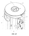
- FIG. 2F is an assembled top view of the Smart Candle Platform of FIG. 2 providing construction and assembly details with the inner cover enclosing the mid-frame with various electronic and operation components affixed therein to the mid-frame and the top cover positioned therein.
- FIG. 3A is a perspective view of an embodiment of the Smart Candle Platform disclosed herein during operation with the outer shell, top cover and inner cover removed to better disclose the inner working portion of the Smart Candle Platform including the mid-frame resting on the base and various interworking components affixed therein.
- FIG. 3B is a perspective view of the other side of the mid-frame and various interworking components affixed therein resting upon the base as disclosed in FIG. 3 and throughout.
- FIG. 3C is a perspective view of the opposite side of the mid-frame with only the fan affixed therein.
- FIG. 3C-1 is a perspective view of the upper portion of the mid-frame with only the fan affixed therein providing a detailed view of the wax collection trough proximate the mid-frame aperture.
- FIG. 3D is an exploded view of the embodiment of the Smart Candle Platform disclosed at FIGS. 2 and 3 illustrating the shape, position and relationship between the interior of the Smart Candle Platform as related to the mid-frame, the fan, the exhaust duct, gasket, ignitor, ignitor assembly, main pcb, battery, sensor pcb and electrical leads connecting the various powered components.
- FIG. 3E is simplified view of a possible scent ring 47 useful with the present disclosure positioned adjacent to a sensor pcb 39 .
- FIG. 4 is a first view of a Smart Candle Platform in operation which embodies at some of the various features disclosed herein.
- FIG. 5 another view of a Smart Candle Platform in operation which embodies at some of the various features disclosed herein.
- Smart Candle Platform Before the present Smart Candle Platform is disclosed and described, it is to be understood that the Smart Candle Platform is not limited to specific methods, specific components, or to particular implementations. It is also to be understood that the terminology used herein is for the purpose of describing particular embodiments only and is not intended to be limiting.
- the word “comprise” and variations of the word, such as “comprising” and “comprises,” means “including but not limited to,” and is not intended to exclude, for example, other components, integers or steps.
- “Exemplary” means “an example of” and is not intended to convey an indication of a preferred or ideal embodiment. “Such as” is not used in a restrictive sense, but for explanatory purposes.
- a control system 30 which may operate the Smart Candle Platform 10 via a remote control 31 .
- These and other components are disclosed herein, and it is understood that when combinations, subsets, interactions, groups, etc. of these components are disclosed that while specific reference of each various individual and collective combinations and permutation of these may not be explicitly disclosed, each is specifically contemplated and described herein, for all potential embodiments of the Smart Candle Platform 10 . This applies to all aspects of this application including, but not limited to, components of a Smart Candle Platform 10 .
- the lighting system of the Smart Candle Platform 10 may be constructed of material of sufficient strength and durability to facilitate low cost production and consumer use for light, decoration and general enjoyment. It is contemplated that in the illustrative embodiment shown in the enclosed figures may be constructed of, but not limited to, any metal or combination of metals including bronze, steel and aluminum; plastics or carbon fiber including Kevlar®, foam-blown polyurethane, thermoplastic polyurethane, ethylene vinyl acetate, other polymers, other thermoplastics, carbon rubber, blown rubber polymers, acrylics, composite materials, natural materials (e.g., rubber, leather, etc.), elastomers, combinations thereof, and/or any other material with suitable characteristics (e.g., compressive strength, stability, elasticity, density).
- plastics or carbon fiber including Kevlar®, foam-blown polyurethane, thermoplastic polyurethane, ethylene vinyl acetate, other polymers, other thermoplastics, carbon rubber, blown rubber polymers, acrylics, composite materials, natural materials (e.g.,
- FIG. 1 provides a front perspective view of one illustrative embodiment of the Smart Candle Platform 10 illustrating an exploded view with call-outs to facilitate description of the various interconnected systems which may be implemented in the Smart Candle Platform 10 as disclosed including without limitation or restriction a lighting system 1 , a sensing system 11 comprised of at least one condition sensor detecting and receiving input from either the environment or the operation of the Smart Candle Platform 10 , a control system 20 and a communications system 30 .
- Illustrative examples could include flame sensing via pyrometer or a thermopile array; flame proximity could be sensed via sensors including an infrared (IR) transmission/receiver type array.
- IR infrared
- the lighting system 1 includes an external facade (outer 2 ) that appears like a typical “dumb” candle and is customizable and may be made of solid wax, which is not used as fuel, plastic, or acrylic or any other material that is suitable and desirable for a particular application.
- the outer shell 2 having an opening 2 a from its along its axis (length) therein may have any shape, color, texture and transparency or opacity desirable to consumers and that can be manufactured by those of ordinary skill in the arts.
- the outer shell 2 could be constructed of any material that allows for transmission or reflection of light and that is sufficient to handle the heat expected during operation of a candle flame including steel, carbon, glass, ceramic, plastic, solid wax, acrylics and or combinations therein, without limitation and/or restriction.
- the outer shell 2 is mounted to a mid-frame 3 which rests on and is attachable to a base 4 .
- the mid-frame 3 and base 4 could be constructed of any material that is of sufficient strength to support the outer shell 2 and the various sensors and systems contemplated by Applicant to be positioned within the outer shell 2 , or within close proximity of the outer shell 2 and mid-frame 3 , for attachment to the mid-frame 3 therein including various metals, including steel, aluminum, carbon fiber, plastic and or combinations therein, without limitation and/or restriction.
- the actual fuel for the Smart Candle Platform 10 is supplied via a fuel cartridge 6 , positioned on the base 4 within the outer shell 2 , and attached to the mid-frame 3 .
- the light and flame are positioned within the opening 2 a of outer shell 2 , similar to a typical “dumb” solid wax candle well known to those of ordinary skill in the art.
- the fuel is typically fed from the bottom such that the lighting system 1 flame (not shown) is generally positioned at the top of the external facade (outer shell 2 ) of the Smart Candle Platform 10 creating a uniform look and feel for the natural flame candle experience.
- the Smart Candle Platform 10 as disclosed herein may use a wick and solid wax for its fuel in one embodiment. Wax from soy, beeswax, paraffin, soy, palm, essential oils and or combinations therein.
- Fuel cartridge 6 as disclosed is not limited to a wick and solid wax and that other fuels that may be combusted for production of a pleasant flame and/or odor and may be substituted without limitation including propane, butane, liquid wax, solid wax pellets, and/or natural and man-made oils.
- the Smart Candle Platform 10 may be configured to produce candle light using a natural wax candle as its fuel source or any other fuel source which is desirable and capable of producing light including wax from soy, beeswax, paraffin, soy, palm, essential oils and or combinations therein.
- the Smart Candle Platform 10 may be configured to produce candle light using a fuel cartridge 6 as shown herein.
- Liquid fuels (oils) available as fuel may include paraffin, soy, hemp, fatty acid, essential oils and or combinations therein. Further, one of ordinary skill will appreciate that the fuel chosen may be odor free or have fragrance added for an enhanced experience, without limitation or restriction. Although not shown, it is contemplated that fragrance could be added to the Smart Candle Platform 10 as disclosed by either addition directly to the fuel burned or via a separate tank or container type system having its own controls, without limitation or restriction. Although not shown, it is also contemplated that fragrance could be added to the Smart Candle Platform as disclosed via an electrical system that only “heats” or “re-heats” the scented/fragrant oils/materials through a system of electrical resistors vs. combustion.
- Applicant incorporates by reference herein the following US patents related to fuel control systems and auto-feeding systems as related to candles and lighting systems including: U.S. Pat. Nos. 4,186,430; 6,030,093; 5,722,763; 5,688,040; 5,424,928; 4,566,055; 4,260,365; 4,186,430; 3,867,625; 3,091,106; and 343,461. Applicant incorporates the preceding US Patents for further enablement and description of the present disclosure without admission as to the scope of teaching or the relevance of any particular reference or combinations of references as related to the patentability of the present disclosure.
- a basic control system 20 includes a “hard” on/off switch 9 which could be positioned on the base 4 or the interior or exterior of the outer shell 2 for convenient access with minimal aesthetic distraction.
- a proximity sensor (either a magnetic field type 15 and/or a visual type 16 ) may be positioned proximate the opening 2 a and on or within the outer shell 2 to detect whether there is a physical obstruction or barrier from the outside environment, in relation to the Smart Candle Platform 10 .
- the Smart Candle Platform 10 may be powered internally via a battery 26 that may be mounted to the mid-frame or positioned in the base 4 or within the interior of the shell 2 .
- thermo-electric charging system 27 could be installed alone or in combination with a battery 26 , based on Peltier principles, to produce electrical current for use or supplementation of other power sources, using the heat produced by the burning fuel.
- power could be provided from an external source including a common electrical outlet or solar power system (not shown), all of which are well known to those of ordinary skill in arts.
- the Smart Candle Platform 10 as disclosed has an ignition control system 21 which ignites the fuel delivered via the fuel cartridge 6 through generation of an arc via an ignitor 7 , which is well known to one of ordinary skill in the art.
- a continuity sensor 12 could be positioned proximate the ignitor 7 and in communication with the control system 20 to monitor the position of the fuel cartridge in the base 4 to ensure proper engagement/contact prior to ignition of the fuel (wick). (Not shown) (See FIGS. 2E-3B and supporting description therein for additional enabling description for this embodiment)
- the control system 20 of the Smart Candle Platform 10 may also include a fuel control system 25 connected to a fuel level sensor 17 which could be used to provide an alert to the user that more fuel is needed, per any one of the communication methods described further herein.
- the fuel level sensor 17 could be connected to an automated fuel feed system 28 (not shown) allowing for the introduction of more fuel from a fuel storage system 29 (not shown) into the fuel cartridge 6 .
- the fuel level could be sensed via an optical camera system.
- the fuel level sensor 17 could signal the fuel control system 25 to auto-feed the wick and/or the wax of the system, subject to the particular fuel and configuration chosen. (See also FIGS. 2E-3B and supporting description therein for additional enabling description for this embodiment)
- the control system 20 of the Smart Candle Platform 10 may also include an extinguisher sub-system 22 that could be comprised of an electrically powered fan 8 (electrically connected to a power source—not shown) to “blow out” the flame when the Smart Candle Platform 10 is turned off via the control system 20 or when one of the installed sensors of the sensor system 11 detects a dangerous condition including for example and without limitation the following: an accelerometer 13 and/or gyroscope 14 working alone or in combination has/have detected the Smart Candle Platform 10 has changed position (tipping/tipped over) producing a fire hazard, sending a signal to the control system 20 to activate the fan 8 to “blow out” the flame (burning fuel) re-establishing “safe” conditions to the operation the Smart Candle Platform 10 .
- an extinguisher sub-system 22 could be comprised of an electrically powered fan 8 (electrically connected to a power source—not shown) to “blow out” the flame when the Smart Candle Platform 10 is turned off via the control system 20 or when one of the installed sensors
- extinguisher systems 22 are contemplated and would include without restriction or limitation pneumatic piston and bladder combinations that would generate and disperse a blast of air useful in putting out a live flame.
- a mechanical choke such as butterfly valve, could be positioned proximate the flame and could be engaged for a similar purpose to snuff out the flame by limiting or restricting air to the live flame.
- the control system 20 may initiate extinguishment of the flame via the extinguisher system 22 (via exhaust duct 33 and fan 8 as discussed at FIGS. 2-3 ) and/or the ignition system 21 by removing fuel from the flame and/or disabling the ignitor 7 , to disable operation of the Smart Candle Platform 10 . (See FIGS. 2E-3 and supporting description therein for additional enabling description for this embodiment)
- the Smart Candle Platform 10 would have at least one control system 20 , which could be an infrared (IR) remote control type 23 working within line-of-sight of the Smart Candle Platform 10 .
- the remote control 23 would control the on/off switch 9 (not shown) mounted on the Smart Candle Platform 10 which may also control (trigger) the ignitor 7 of the ignition control system 21 and the fan 8 of the extinguisher system 22 deployed in the Smart Candle Platform 10 .
- the Smart Candle Platform 10 would have at least one control system 20 , which could be a timer system 24 which could work with the ignition system 21 and extinguisher control system 22 of the Smart Candle Platform 10 .
- the timer 24 would also control of on/off switch 9 (not shown) mounted on the Smart Candle Platform 10 which may also control (trigger) the ignitor 7 of the ignition control system 21 and the fan 8 of the extinguisher system 22 deployed in the Smart Candle Platform 10 , on either a pre-programmed time period (1 h, 2 h and/or 4 h) or a variable period time to be selected by the user (59 minutes). Upon expiration of the selected time period, the Smart Candle Platform 10 would shut down automatically.
- the Smart Candle Platform 10 disclosed and claimed herein may be configured with a communication system 30 including appropriate transmitters and receivers, subject to the particular communication installed therein.
- the communication system 30 may allow communication and control between individual Smart Candle Platforms 10 and a smart phone (not shown) having a software application installed therein via communication with WiFi, Bluetooth, cellular and/audio type systems and combinations therein.
- the communication system 30 may also be configured to allow communication between groups of Smart Candle Platforms 10 allowing multi-device and zone type control via the various types of communication systems that may be installed therein.
- the various elements of the Smart Candle Platform 10 may be separately formed and later engaged with one another (e.g., via mechanical fasteners, material fusing, chemical adhesives, etc.) or integrally formed.
- the materials used to construct the Smart Candle Platform 10 and various elements thereof will vary depending on the specific application of the Smart Candle Platform 10 , but it is contemplated that steel, Aluminium, polymers, other synthetic materials, natural materials, and/or combinations thereof will be especially useful for some applications.
- the above-referenced elements may be constructed of any material known to those skilled in the art or later developed, which material is appropriate for the specific application of the Smart Candle Platform 10 , without departing from the spirit and scope of the Smart Candle Platform 10 as disclosed and claimed herein.
- FIGS. 2-3 In another embodiment of the Smart Candle Platform 10 as disclosed and shown throughout FIGS. 2-3 includes an external facade (outer shell 2 ) that appears like a typical “dumb” candle and is customizable. Although shown having a round shape, the outer shell 2 having opening 2 a therein may have any shape, color, texture and transparency or opacity desirable to consumers and that can be manufactured by those of ordinary skill in the arts that allows for transmission or reflection of all or portions of the electromagnetic spectrum or selected portions to enable a sensor(s), as disclosed or in use, that is sufficient to handle the heat expected during operation of a candle flame including steel, carbon, glass, ceramic, plastic and or combinations therein, without limitation and/or restriction.
- the outer shell 2 could also be constructed of any material that is pleasing to a user and may be constructed of plastic or wax to emulate a pillar candle.
- the outer shell can be constructed to be removable and/or replaceable so that the user may switch the outer shells to better match their décor or subject to holidays—red or green for Christmas and black or orange for Halloween or Fall by way of example and without limitation.
- FIG. 2 is a perspective of the exterior portion of another embodiment of the Smart Candle Platform 10 as disclosed herein during operation.
- the Smart Candle Platform 10 has a live flame 100 positioned with discharge from an ignitor ring 36 surrounded by a top cover 32 positioned in the upper portion outer shell 2 .
- a candle 41 composed of wax having a wick 41 a is the fuel and may have all attributes previously attributed and discussed regarding FIG. 1 .
- FIG. 2A is an exploded view of the Smart Candle Platform of FIG. 2 providing further construction and fabrication details. As shown in FIG.
- the Smart Candle Platform 10 may be fabricated with an outer shell 2 having an opening 2 a therein.
- An inner cover 31 also having main aperture 31 a is shown positioned within and enclosed by outer shell 2 with top cover 32 positioned upon the upper portion of inner cover 31 .
- the outer shell 2 has a hollow interior connecting an upper end and a lower end with a rim 2 b positioned around the interior of the upper end, together forming a first opening 2 a .
- An inner cover 31 having a hollow interior connecting an upper end and an open lower end is shown with a generally flat plateau at the upper end 31 d formed by shelf 31 c .
- a main aperture 31 a is formed therein. The inner cover 31 is positioned within the first opening of the outer shell 2 a .
- outer shell 2 and inner sleeve 31 may be constructed without rim 2 b , plateau 31 d and shelf 31 c without restriction or limitation as required for a particular configuration or application.
- various smaller apertures for securement assemblies 31 b are positioned proximate and around main aperture 31 b which when assembled are also proximate and positioned around opening 2 a of the outer shell 2 .
- Top cover 32 is non-conductive and acts as an insulator between inner cover 31 and outer shell 2 .
- Top cover aperture 32 a , first opening 2 a , and main aperture 31 a align. Further, top cover 32 may be aesthetically pleasing and may be either light reflective in support of wick 41 a and flame 100 during operation.
- top cover 32 is disclosed and described as being composed of glass, any material suitable for the particular application of a Smart Candle Platform 10 may be chosen including wax, plastic, ceramics as well as various metals including steel, aluminium and bronze and various combinations therein which may be reflective or optically transparent, as required by a particular application. Further, top cover 32 may have be configured to have an outer surface similar to outer shell 2 which may also be wax, having heat resistant properties as required by its proximity to the live flame.
- FIG. 2B of the Smart Candle Platform illustrates one embodiment of a fuel (wax) and fuel feed system 28 shown as a candle assembly 5 .
- the candle assembly 5 is a feeder tube 40 configured to be positioned in the aperture of the inner cover sleeve 31 a , a wax candle 41 with wick 41 a , spring 43 and candle pusher 42 .
- One embodiment of the Smart Candle Platform 10 disclosed herein may be configured based on FIGS. 2A-2B wherein outer shell 2 , top cover 32 and inner cover 31 having main aperture 31 a therein, with candle assembly 5 positioned internally therein, upon engagement between base 4 and inner sleeve 31 forms a simple embodiment of a working live flame Smart Candle Platform 10 .
- 2B-1 is a bottom view of the base 4 with the base cap 4 a removed to illustrate the candle assembly 5 (feeder tube 40 , candle 41 , candle pusher 42 and spring 43 ) positioned therein with mid-frame 3 .
- base 4 may be configured with a plurality of base feet 44 .
- base 4 may also have base tab 4 g positioned around the perimeter of the base 4 for coupled engagement with recesses 31 e positioned around the perimeter of inner sleeve 31 or for coupled engagement with recesses positioned in the lower portion of the mid-frame 3 .
- base tab 4 g positioned around the perimeter of the base 4 for coupled engagement with recesses 31 e positioned around the perimeter of inner sleeve 31 or for coupled engagement with recesses positioned in the lower portion of the mid-frame 3 .
- the wax candle 41 is meant to advance automatically or semi-automatically via candle pusher 42 positioned against the bottom of wax candle 41 and is in communication with spring 43 which is positioned interior of base cap 4 a of base 4 as shown in further detail in FIG. 2C .
- base 4 and base cap 4 a work together with the lower end of inner sleeve 31 to operate as a wax lock during operation of the Smart Candle Platform 10 .
- the base 4 and base cap 4 a may work together with the lower end of inner sleeve 31 to contain a fuel refill and/or cartridge in other embodiments configured for a fuel cartridge 6 which could be configured for use of liquid fuel—such as soy oil.
- a canister having a size and shape similar to the feeder tube configured with a wick 41 a distending from an aperture positioned in the upper portion of the canister, wherein in the upper portion is a removable lid, could be one embodiment of fuel cartridge 6 useful for liquid fuel.
- FIG. 2D is an assembled view of the Smart Candle Platform 10 of FIG. 2 providing further construction and assembly details for the slidable affixation of the lower portion of the inner cover to the base 4 , base feet 44 and base cap 4 a .
- base 4 is configured with annular base ridge 4 b , base shelf 4 c and base void 4 e for slotted contact and engagement with the lower end of inner sleeve 31 shown in FIG. 2D .
- Inclusion of base tab 4 g allows for fixed uni-directional engagement and assembly.
- Base 4 may be attached to the inner cover 31 via base fastener assemblies 4 f which are apertures in which any fastener (glue, screws, bolts, expansion pegs and/or combinations therein) (not shown) may be positioned to fix the end of inner sleeve 31 to base 4 .
- FIG. 2D-1 is an assembled bottom view of the base 4 and inner cover 31 with the base cap 4 a removed as well as several base foot 44 to better show base pads 4 h .
- FIG. 2E is an assembled view of the Smart Candle Platform 10 disclosed herein as embodied in either FIG. 1, 2 , or 3 configured with an inner cover 31 enclosing a mid-frame structure 3 with various electronic and operation components affixed therein.
- the mid-frame 3 is configured to engage with and be surrounded by an inner sleeve 31 having a generally round shape.
- the mid-frame 3 includes an upper annular shelf 3 a as well as a lower annular shelf 3 b which are generally round in shape.
- FIGS. 1-3 One of ordinary skill will appreciate the present disclosure ( FIGS. 1-3 ) is not limited to one particular shape but that the combination of outer shell 2 , opening 2 a , inner sleeve 31 and mid-frame 3 can be configured to any shape desired with this concentric interconnection design between the preceding elements. As shown in FIG.
- upper annular shelf 3 a and lower annular shelf 3 b allow for the creation of a mid-frame axial compartment 3 c into which a main pcb (printed circuit board) 38 may be affixed allowing for a control system 20 as discussed further herein.
- main pcb printed circuit board
- the main pcb 38 may have the following systems, system controls or connections, via either analog or digital systems, installed therein including a sensor system 11 , a continuity sensor 12 , an accelerometer 13 , a gyroscope 14 , a proximity sensor—via magnetic field 15 , proximity sensor—via visual 16 , a fuel level sensor 17 , a flame sensor 18 , a control system 20 , an ignition control system 21 , an extinguisher system 22 , an infrared (IR) remote control 23 , a timer 24 , a fuel control system 25 , a power source-battery 26 , a thermo-electric charging (Peltier) 27 , a fuel feed system 28 (including controls), a communications system 30 , including either or both a wifi or bluetooth transmitter(s) and receiver(s), and combinations therein collectively working separately or together supporting operation of a Smart Candle Platform 10 or Smart Candle Platforms 10 including a mesh network of Smart Candle Platforms 10 .
- a sensor system 11 including
- the recesses created by the upper and lower annular shelves ( 3 a , 3 b ) provide adequate space to position the various components and systems disclosed through-out to allow for a compact, safe, aesthetically pleasing operational Smart Candle Platform 10 including for example fan 8 (shown in FIG. 2E ), battery 26 , ignition control system 21 , ignition control system—electrical leads 21 a and ignitor trough 34 .
- the electrical connections between the various systems requiring electrical power may be positioned adjacent to and in either the ignitor trough 34 and/or mid-frame axial compartment 3 c or other recesses located in the mid-frame 3 or combinations therein.
- a restricted access panel or cover 70 having tab 72 positioned in base 4 may be required to ensure user access to the electronic components is limited as required by regulatory bodies and/or as recommended consumer product safety practices. (See FIG. 2B-1 and FIG. 2D )
- FIG. 2F is an assembled top view of the Smart Candle Platform of FIG. 2 providing construction and assembly details with the inner cover 31 enclosing the mid-frame 3 with various electronic and operation components affixed therein to the mid-frame 3 and the top cover 32 positioned therein.
- FIG. 3A provides another perspective view of the Smart Candle Platform 10 disclosed herein during operation with the outer shell 2 , top cover 32 and inner cover 31 removed to better disclose the inner working components of the Smart Candle Platform 10 including sensor pcb 39 with the mid-frame 3 resting on the base 4 .
- ignitor ring 36 is positioned on the upper portion of the mid-frame 3 extending out from the inner sleeve 31 .
- sensor pcb 39 is positioned on the upper portion of the mid-frame 3 just under the inner sleeve 31 .
- the sensor pcb 38 may have the following systems, system controls, or connections to it, installed therein including a sensor system 11 , a continuity sensor 12 , accelerometer 13 , gyroscope 14 , proximity sensor—magnetic field 15 , proximity sensor—visual 16 , fuel level sensor 17 , flame sensor 18 , control system 20 , ignition control system 21 , extinguisher system 22 , infrared (IR) remote control 23 , timer 24 , fuel control system 25 , power source-battery 26 , thermo-electric charging (Peltier) 27 , fuel feed system 28 (controls), communications system 30 , including either or both a wifi or bluetooth transmitter(s) and receiver(s) and combinations therein collectively working separately or together supporting operation of the Smart Candle Platform 10 .
- a wifi or bluetooth transmitter(s) and receiver(s) and combinations therein collectively working separately or together supporting operation of the Smart Candle Platform 10 .
- FIG. 3B is a perspective view of the other side of the mid-frame 3 including mid-frame lower tab 3 d , mid-frame exhaust passage 3 e and mid-frame aperture 3 f having a main pcb 38 affixed in the mid-frame axial compartment 3 c located between the mid-frame upper and lower annual shelves ( 3 a , 3 b ) resting upon the base 4 and positioned for engagement with the base fastener assemblies 4 f proximate the base ridge 4 b and base shelf 4 c .
- fan 8 is positioned in a recess located just under the upper mid-frame shelf 3 a .
- exhaust duct 33 is positioned in mid-frame exhaust passage 3 e on the upper face of the mid-frame 3 in fluid communication with ignitor ring assembly 35 and ignitor ring 36 .
- FIG. 3B-1 is a detailed view of FIG. 3B with the base 4 removed to better illustrate the pcb 38 affixed to the mid-frame 3 in the mid-frame axial frame compartment and the position of the continuity sensor 12 between the lower portion of the mid-frame 3 and the base 4 .
- FIG. 3C is perspective view of the mid-frame 3 with only the fan 8 affixed to best illustrate the various components of the mid-frame 3 to illustrate the other side of the mid-frame 3 .
- FIG. 30-1 is a perspective view of the upper portion of the mid-frame 3 with only the fan 8 and exhaust duct 33 affixed therein.
- the upper portion of mid-frame is configured with a wax overflow collection trough proximate the mid-frame aperture 3 f and mid-frame exhaust passage 3 e for engagement with exhaust duct 33 .
- fan 8 connected to exhaust duct 33 may be used as part of the extinguishment system 22 i.e.
- FIG. 3D is an exploded view of Smart Candle Platform 10 providing additional illustration of one embodiment therein particularly as related to the shape, position and relationship between the interior of the Smart Candle Platform 10 as related to the mid-frame 3 , the fan 8 , exhaust duct 3 , ignitor 21 b , ignitor assembly 35 positioned under ignitor ring 36 and base 4 , main pcb 38 , battery 26 , sensor pcb 39 and electrical leads (ignition control system 21 a and battery leads) connecting the various powered components of Smart Candle Platform 10 .
- the sensor pcb 39 is illustrated having infrared (IR) sensors 45 and thermopiles 46 arrayed and arranged around the circumference of the sensor pcb 39 .
- IR infrared
- Ignitor ring 36 having the clover-leaf shape as shown through-out, which surrounds the wick 41 a and flame 100 , has been found to be one configuration allowing multiple ignitors 21 b for improved control of wick 41 a and flame 100 solving the problem(s) of wick and flame migration.
- FIG. 3E illustrates one embodiment of a scent ring 47 useful with the present disclosure positioned adjacent to a sensor pcb 39 and ignitor ring 36 .
- the scent ring 47 may have any shape that works with a particular configuration of the Smart Candle Platform 1 disclosed herein. Further, the scent ring 47 may be used with a sensor pcb 39 and ignitor ring 36 as illustrated or may be used in a Smart Candle Platform 10 configured for use without a mid-frame 3 or ignitor ring 36 with the scent ring 47 positioned proximate live flame 100 to provide heat which may be useful in warming-up the scent ring 47 to activate the scent therein for distribution.
- the scent ring 47 may be positioned inside the sensor pcb 39 or external to the sensor pcb 39 as shown, without limitation or restriction, as required for a particular application or configuration.
- the Smart Candle Platform is not limited to the specific embodiments pictured and described herein, but is intended to apply to all similar apparatuses and methods for providing the various benefits and/or features of a Smart Candle Platform. Modifications and alterations from the described embodiments will occur to those skilled in the art without departure from the spirit and scope of the Smart Candle Platform. It is understood that the Smart Candle Platform as disclosed herein extends to all alternative combinations of one or more of the individual features mentioned, evident from the text and/or drawings, and/or inherently disclosed. All of these different combinations constitute various alternative aspects of the Smart Candle Platform and/or components thereof. The embodiments described herein explain the best modes known for practicing the Smart Candle Platform and/or components thereof and will enable others skilled in the art to utilize the same. The claims are to be construed to include alternative embodiments to the extent permitted by the prior art.
Landscapes
- Engineering & Computer Science (AREA)
- General Engineering & Computer Science (AREA)
- Chemical & Material Sciences (AREA)
- Combustion & Propulsion (AREA)
- Mechanical Engineering (AREA)
- Computer Networks & Wireless Communication (AREA)
- Signal Processing (AREA)
- Human Computer Interaction (AREA)
- Automation & Control Theory (AREA)
- Fats And Perfumes (AREA)
- Non-Portable Lighting Devices Or Systems Thereof (AREA)
Priority Applications (6)
| Application Number | Priority Date | Filing Date | Title |
|---|---|---|---|
| US15/452,704 US9810426B2 (en) | 2016-03-07 | 2017-03-07 | Smart candle platform and system |
| US15/799,249 US10655843B2 (en) | 2016-03-07 | 2017-10-31 | Smart candle platform and system |
| US16/361,187 US10928059B2 (en) | 2016-03-07 | 2019-03-21 | Smart candle platform and system |
| US17/068,516 US11378272B2 (en) | 2016-03-07 | 2020-10-12 | Smart candle platform and system |
| US17/590,510 US11499710B2 (en) | 2016-03-07 | 2022-02-01 | Smart candle platform and system |
| US17/986,232 US11867393B2 (en) | 2016-03-07 | 2022-11-14 | Smart candle platform and system |
Applications Claiming Priority (3)
| Application Number | Priority Date | Filing Date | Title |
|---|---|---|---|
| US201662304628P | 2016-03-07 | 2016-03-07 | |
| US201662396769P | 2016-09-19 | 2016-09-19 | |
| US15/452,704 US9810426B2 (en) | 2016-03-07 | 2017-03-07 | Smart candle platform and system |
Related Child Applications (1)
| Application Number | Title | Priority Date | Filing Date |
|---|---|---|---|
| US15/799,249 Continuation US10655843B2 (en) | 2016-03-07 | 2017-10-31 | Smart candle platform and system |
Publications (2)
| Publication Number | Publication Date |
|---|---|
| US20170254532A1 US20170254532A1 (en) | 2017-09-07 |
| US9810426B2 true US9810426B2 (en) | 2017-11-07 |
Family
ID=59722772
Family Applications (2)
| Application Number | Title | Priority Date | Filing Date |
|---|---|---|---|
| US15/452,704 Active US9810426B2 (en) | 2016-03-07 | 2017-03-07 | Smart candle platform and system |
| US15/799,249 Active 2037-09-17 US10655843B2 (en) | 2016-03-07 | 2017-10-31 | Smart candle platform and system |
Family Applications After (1)
| Application Number | Title | Priority Date | Filing Date |
|---|---|---|---|
| US15/799,249 Active 2037-09-17 US10655843B2 (en) | 2016-03-07 | 2017-10-31 | Smart candle platform and system |
Country Status (6)
| Country | Link |
|---|---|
| US (2) | US9810426B2 (da) |
| EP (1) | EP3426978B1 (da) |
| CN (1) | CN109219721B (da) |
| CA (1) | CA3016715A1 (da) |
| DK (1) | DK3426978T3 (da) |
| WO (1) | WO2017156045A1 (da) |
Cited By (8)
| Publication number | Priority date | Publication date | Assignee | Title |
|---|---|---|---|---|
| US20170268775A1 (en) * | 2014-12-11 | 2017-09-21 | Candle Touch Ltd. | Remotely-controlled candle |
| US20190271467A1 (en) * | 2016-09-16 | 2019-09-05 | Giuseppe SORDA | Casing for lighter and lighter comprising the casing |
| US11378272B2 (en) | 2016-03-07 | 2022-07-05 | Ludela Technologies Llc | Smart candle platform and system |
| US11428343B2 (en) | 2021-01-27 | 2022-08-30 | Joseph Pannullo | Mechanical overfill prevention valve insertable within a fill pipe |
| US11493200B2 (en) | 2020-07-14 | 2022-11-08 | Joseph Pannullo | Liquid fuel burning torch system with automatic fuel replenishment and flame extinguishment |
| US11499710B2 (en) | 2016-03-07 | 2022-11-15 | Ludela Technologies Llc | Smart candle platform and system |
| US11503822B2 (en) * | 2020-07-14 | 2022-11-22 | Joseph Pannullo | Attachable plug for adding features to a torch system |
| US11957120B2 (en) | 2020-07-14 | 2024-04-16 | Joseph Pannullo | Torch system with predictive control of automatic fuel replenishment |
Families Citing this family (12)
| Publication number | Priority date | Publication date | Assignee | Title |
|---|---|---|---|---|
| US10161584B2 (en) * | 2015-09-03 | 2018-12-25 | Luminara Worldwide, Llc | Electric lighting device with scent cartridge |
| DK3426978T3 (da) | 2016-03-07 | 2021-10-04 | Ludela Tech Llc | Intelligent lysplatform og system |
| US10928059B2 (en) * | 2016-03-07 | 2021-02-23 | Ludela Technologies Llc | Smart candle platform and system |
| US20190189885A1 (en) * | 2017-12-15 | 2019-06-20 | Therm-Tech As | Thermoelectric generator |
| CA3094692A1 (en) * | 2018-03-21 | 2019-09-26 | Ludela Technologies Inc. | Smart candle platform and system |
| US10738986B1 (en) * | 2019-02-01 | 2020-08-11 | Pyllr, LLC | Lighting device that interfaces with a communication device |
| AU2020240131B2 (en) * | 2019-03-21 | 2023-06-15 | Ludela Technologies Llc | Smart candle platform and system |
| JP2022534194A (ja) * | 2019-06-01 | 2022-07-28 | ルデラ テクノロジーズ エルエルシー | スマートキャンドルプラットフォームおよびシステム |
| CN110938494A (zh) * | 2019-12-19 | 2020-03-31 | 桂东县德古文化传播有限公司 | 一种工艺蜡烛生产用灌装设备 |
| US10842146B1 (en) * | 2020-07-14 | 2020-11-24 | Joseph Pannullo | Insect repellent torch system with automatic fuel replenishment |
| CN112063459B (zh) * | 2020-08-03 | 2023-05-12 | 南通亚泰蜡业工艺品有限公司 | 一种燃油型电子蜡烛 |
| US20230068843A1 (en) * | 2021-08-25 | 2023-03-02 | John Francis Senrau | Candle with lighting embodiments |
Citations (13)
| Publication number | Priority date | Publication date | Assignee | Title |
|---|---|---|---|---|
| US343461A (en) | 1886-06-08 | Franz kuntz | ||
| US3091106A (en) | 1959-06-10 | 1963-05-28 | Crouch Brockway | Candelabra |
| US3867625A (en) | 1973-07-16 | 1975-02-18 | Charles C Whalen | Candle lamp |
| US4186430A (en) | 1977-08-09 | 1980-01-29 | Britton Bruce G | Telescoping candle lantern |
| US4260365A (en) | 1978-03-30 | 1981-04-07 | Valley Candle Mfg. Co., Inc. | Candle lamp |
| US4566055A (en) | 1982-08-22 | 1986-01-21 | Klees Gary W | Candle holder |
| US5057005A (en) * | 1989-05-25 | 1991-10-15 | Kwok Wai Shi | Candle device |
| US5424928A (en) | 1993-06-10 | 1995-06-13 | Northern Lights, Inc. | Lantern |
| US5688040A (en) | 1996-01-17 | 1997-11-18 | Klees; Garry W. | Portable, tub candle lantern |
| US5722763A (en) | 1996-09-30 | 1998-03-03 | Chen; Kao-San | Lantern |
| US6030093A (en) | 1998-09-15 | 2000-02-29 | Draper; Gregory L. | Multiple candle lantern |
| US6328935B1 (en) * | 2000-07-06 | 2001-12-11 | Custom Essence, Inc. | Aroma dispenser for candle |
| US6733279B2 (en) * | 2001-04-05 | 2004-05-11 | Harold D. Thigpen | Remote microcontrolled laser oil lamp |
Family Cites Families (9)
| Publication number | Priority date | Publication date | Assignee | Title |
|---|---|---|---|---|
| SE7316797L (da) * | 1973-12-12 | 1975-06-13 | Anders Benson | |
| US4755135A (en) * | 1985-11-19 | 1988-07-05 | Kwok Wai Shi | Candle device |
| US4926297A (en) * | 1989-05-30 | 1990-05-15 | Masters Edward R | Collapsible lantern |
| CN2187731Y (zh) * | 1994-01-11 | 1995-01-18 | 林振毓 | 一种可调节行程的筒状封闭式节能烛套 |
| GB9720735D0 (en) * | 1997-10-01 | 1997-11-26 | Mason Mfg Ltd | Candles |
| WO2008061293A1 (en) * | 2006-11-24 | 2008-05-29 | Gravity Candles Pty Ltd | Candle system |
| CN203258627U (zh) * | 2013-02-28 | 2013-10-30 | 伍启刚 | 蜡烛光控烛台 |
| CN204534425U (zh) * | 2015-04-13 | 2015-08-05 | 方舰 | 一种仿真飘动火焰装置 |
| DK3426978T3 (da) | 2016-03-07 | 2021-10-04 | Ludela Tech Llc | Intelligent lysplatform og system |
-
2017
- 2017-03-07 DK DK17763940.8T patent/DK3426978T3/da active
- 2017-03-07 WO PCT/US2017/021222 patent/WO2017156045A1/en active Application Filing
- 2017-03-07 CA CA3016715A patent/CA3016715A1/en active Pending
- 2017-03-07 US US15/452,704 patent/US9810426B2/en active Active
- 2017-03-07 CN CN201780028166.6A patent/CN109219721B/zh active Active
- 2017-03-07 EP EP17763940.8A patent/EP3426978B1/en active Active
- 2017-10-31 US US15/799,249 patent/US10655843B2/en active Active
Patent Citations (13)
| Publication number | Priority date | Publication date | Assignee | Title |
|---|---|---|---|---|
| US343461A (en) | 1886-06-08 | Franz kuntz | ||
| US3091106A (en) | 1959-06-10 | 1963-05-28 | Crouch Brockway | Candelabra |
| US3867625A (en) | 1973-07-16 | 1975-02-18 | Charles C Whalen | Candle lamp |
| US4186430A (en) | 1977-08-09 | 1980-01-29 | Britton Bruce G | Telescoping candle lantern |
| US4260365A (en) | 1978-03-30 | 1981-04-07 | Valley Candle Mfg. Co., Inc. | Candle lamp |
| US4566055A (en) | 1982-08-22 | 1986-01-21 | Klees Gary W | Candle holder |
| US5057005A (en) * | 1989-05-25 | 1991-10-15 | Kwok Wai Shi | Candle device |
| US5424928A (en) | 1993-06-10 | 1995-06-13 | Northern Lights, Inc. | Lantern |
| US5688040A (en) | 1996-01-17 | 1997-11-18 | Klees; Garry W. | Portable, tub candle lantern |
| US5722763A (en) | 1996-09-30 | 1998-03-03 | Chen; Kao-San | Lantern |
| US6030093A (en) | 1998-09-15 | 2000-02-29 | Draper; Gregory L. | Multiple candle lantern |
| US6328935B1 (en) * | 2000-07-06 | 2001-12-11 | Custom Essence, Inc. | Aroma dispenser for candle |
| US6733279B2 (en) * | 2001-04-05 | 2004-05-11 | Harold D. Thigpen | Remote microcontrolled laser oil lamp |
Cited By (10)
| Publication number | Priority date | Publication date | Assignee | Title |
|---|---|---|---|---|
| US20170268775A1 (en) * | 2014-12-11 | 2017-09-21 | Candle Touch Ltd. | Remotely-controlled candle |
| US10393379B2 (en) * | 2014-12-11 | 2019-08-27 | Candle Touch Ltd. | Remotely-controlled candle |
| US11378272B2 (en) | 2016-03-07 | 2022-07-05 | Ludela Technologies Llc | Smart candle platform and system |
| US11499710B2 (en) | 2016-03-07 | 2022-11-15 | Ludela Technologies Llc | Smart candle platform and system |
| US11867393B2 (en) | 2016-03-07 | 2024-01-09 | Ludela Technologies Llc | Smart candle platform and system |
| US20190271467A1 (en) * | 2016-09-16 | 2019-09-05 | Giuseppe SORDA | Casing for lighter and lighter comprising the casing |
| US11493200B2 (en) | 2020-07-14 | 2022-11-08 | Joseph Pannullo | Liquid fuel burning torch system with automatic fuel replenishment and flame extinguishment |
| US11503822B2 (en) * | 2020-07-14 | 2022-11-22 | Joseph Pannullo | Attachable plug for adding features to a torch system |
| US11957120B2 (en) | 2020-07-14 | 2024-04-16 | Joseph Pannullo | Torch system with predictive control of automatic fuel replenishment |
| US11428343B2 (en) | 2021-01-27 | 2022-08-30 | Joseph Pannullo | Mechanical overfill prevention valve insertable within a fill pipe |
Also Published As
| Publication number | Publication date |
|---|---|
| US20170254532A1 (en) | 2017-09-07 |
| WO2017156045A1 (en) | 2017-09-14 |
| US20180066840A1 (en) | 2018-03-08 |
| US10655843B2 (en) | 2020-05-19 |
| CN109219721A (zh) | 2019-01-15 |
| DK3426978T3 (da) | 2021-10-04 |
| CN109219721B (zh) | 2020-12-15 |
| EP3426978A1 (en) | 2019-01-16 |
| EP3426978B1 (en) | 2021-06-30 |
| CA3016715A1 (en) | 2017-09-14 |
| EP3426978A4 (en) | 2019-10-09 |
Similar Documents
| Publication | Publication Date | Title |
|---|---|---|
| US10655843B2 (en) | Smart candle platform and system | |
| US10928059B2 (en) | Smart candle platform and system | |
| US11378272B2 (en) | Smart candle platform and system | |
| US20230175688A1 (en) | Smart candle platform and system | |
| US20080026335A1 (en) | Artificial campfire apparatus | |
| US9074763B2 (en) | Spill proof alcohol burner | |
| CA3134514C (en) | Smart candle platform and system | |
| US12104783B2 (en) | Smart candle platform and system | |
| US9835328B2 (en) | Multipurpose outdoor gas fire place | |
| AU2019240389B2 (en) | Smart candle platform and system | |
| US20220235929A1 (en) | Smart candle platform and system |
Legal Events
| Date | Code | Title | Description |
|---|---|---|---|
| STCF | Information on status: patent grant |
Free format text: PATENTED CASE |
|
| AS | Assignment |
Owner name: LUDELA, INC., NEVADA Free format text: ASSIGNMENT OF ASSIGNORS INTEREST;ASSIGNORS:BIANCHINI, JAMIE;BAUSWELL, ERIC DAVID;WAFLER, DANNY RAY;SIGNING DATES FROM 20171026 TO 20171027;REEL/FRAME:044585/0639 |
|
| AS | Assignment |
Owner name: LUDELA TECHNOLOGIES INC., CALIFORNIA Free format text: ASSIGNMENT OF ASSIGNORS INTEREST;ASSIGNOR:LUDELA PBC;REEL/FRAME:050824/0983 Effective date: 20191018 |
|
| AS | Assignment |
Owner name: LUDELA, PBC, OREGON Free format text: CHANGE OF NAME;ASSIGNOR:LUDELA, INC.;REEL/FRAME:051020/0729 Effective date: 20180205 |
|
| AS | Assignment |
Owner name: LUDELA TECHNOLOGIES INC., CALIFORNIA Free format text: CORRECTIVE ASSIGNMENT TO CORRECT THE NAME OF ASSIGNOR FROM LUDELA PBC TO LUDELA, PBC PREVIOUSLY RECORDED ON REEL 050824 FRAME 0983. ASSIGNOR(S) HEREBY CONFIRMS THE CORRECT THE NAME OF ASSIGNOR FROM LUDELA PBC TO LUDELA, PBC;ASSIGNOR:LUDELA, PBC;REEL/FRAME:053953/0312 Effective date: 20191018 |
|
| AS | Assignment |
Owner name: LUDELA TECHNOLOGIES LLC, CALIFORNIA Free format text: CONVERSION;ASSIGNOR:LUDELA TECHNOLOGIES INC.;REEL/FRAME:054190/0607 Effective date: 20200429 Owner name: LUDELA TECHNOLOGIES LLC, CALIFORNIA Free format text: CHANGE OF NAME;ASSIGNOR:LUDELA TECHNOLOGIES INC.;REEL/FRAME:054193/0072 Effective date: 20200429 |
|
| FEPP | Fee payment procedure |
Free format text: ENTITY STATUS SET TO SMALL (ORIGINAL EVENT CODE: SMAL); ENTITY STATUS OF PATENT OWNER: SMALL ENTITY |
|
| MAFP | Maintenance fee payment |
Free format text: PAYMENT OF MAINTENANCE FEE, 4TH YR, SMALL ENTITY (ORIGINAL EVENT CODE: M2551); ENTITY STATUS OF PATENT OWNER: SMALL ENTITY Year of fee payment: 4 |