US9809987B2 - Seating system with tiltable deck and belt drive - Google Patents
Seating system with tiltable deck and belt drive Download PDFInfo
- Publication number
- US9809987B2 US9809987B2 US15/061,610 US201615061610A US9809987B2 US 9809987 B2 US9809987 B2 US 9809987B2 US 201615061610 A US201615061610 A US 201615061610A US 9809987 B2 US9809987 B2 US 9809987B2
- Authority
- US
- United States
- Prior art keywords
- deck
- seating system
- riser
- recited
- actuator
- Prior art date
- Legal status (The legal status is an assumption and is not a legal conclusion. Google has not performed a legal analysis and makes no representation as to the accuracy of the status listed.)
- Active
Links
Images


Classifications
-
- E—FIXED CONSTRUCTIONS
- E04—BUILDING
- E04H—BUILDINGS OR LIKE STRUCTURES FOR PARTICULAR PURPOSES; SWIMMING OR SPLASH BATHS OR POOLS; MASTS; FENCING; TENTS OR CANOPIES, IN GENERAL
- E04H3/00—Buildings or groups of buildings for public or similar purposes; Institutions, e.g. infirmaries or prisons
- E04H3/10—Buildings or groups of buildings for public or similar purposes; Institutions, e.g. infirmaries or prisons for meetings, entertainments, or sports
- E04H3/12—Tribunes, grandstands or terraces for spectators
- E04H3/123—Telescopic grandstands
-
- A—HUMAN NECESSITIES
- A47—FURNITURE; DOMESTIC ARTICLES OR APPLIANCES; COFFEE MILLS; SPICE MILLS; SUCTION CLEANERS IN GENERAL
- A47C—CHAIRS; SOFAS; BEDS
- A47C1/00—Chairs adapted for special purposes
- A47C1/12—Theatre, auditorium, or similar chairs
- A47C1/121—Theatre, auditorium, or similar chairs having tipping-up seats
-
- A—HUMAN NECESSITIES
- A47—FURNITURE; DOMESTIC ARTICLES OR APPLIANCES; COFFEE MILLS; SPICE MILLS; SUCTION CLEANERS IN GENERAL
- A47C—CHAIRS; SOFAS; BEDS
- A47C1/00—Chairs adapted for special purposes
- A47C1/12—Theatre, auditorium, or similar chairs
- A47C1/124—Separate chairs, connectible together into a row
-
- A—HUMAN NECESSITIES
- A47—FURNITURE; DOMESTIC ARTICLES OR APPLIANCES; COFFEE MILLS; SPICE MILLS; SUCTION CLEANERS IN GENERAL
- A47C—CHAIRS; SOFAS; BEDS
- A47C1/00—Chairs adapted for special purposes
- A47C1/12—Theatre, auditorium, or similar chairs
- A47C1/126—Theatre, auditorium, or similar chairs stowable in floor or wall
-
- B—PERFORMING OPERATIONS; TRANSPORTING
- B66—HOISTING; LIFTING; HAULING
- B66D—CAPSTANS; WINCHES; TACKLES, e.g. PULLEY BLOCKS; HOISTS
- B66D1/00—Rope, cable, or chain winding mechanisms; Capstans
- B66D1/02—Driving gear
- B66D1/14—Power transmissions between power sources and drums or barrels
- B66D1/20—Chain, belt, or friction drives, e.g. incorporating sheaves of fixed or variable ratio
-
- B—PERFORMING OPERATIONS; TRANSPORTING
- B66—HOISTING; LIFTING; HAULING
- B66D—CAPSTANS; WINCHES; TACKLES, e.g. PULLEY BLOCKS; HOISTS
- B66D1/00—Rope, cable, or chain winding mechanisms; Capstans
- B66D1/60—Rope, cable, or chain winding mechanisms; Capstans adapted for special purposes
Definitions
- Seating risers are often used in auditoriums, gymnasiums, stadiums, and event halls, as examples, to accommodate spectators on portable seats, such as folding chairs, or on seats that are affixed to the risers. Certain facilities may require seating risers that are capable of being moved between a retracted position for storage and a deployed position for use.
- a seating system includes, among other things, a riser including a tiltable deck.
- Another seating system includes, among other things, a drive system for moving a riser.
- the drive system includes a sprocket configured to engage a belt.
- FIG. 1A is a side view of a seating system in a retracted position.
- FIG. 1B is a side view of the seating system of FIG. 1A in a deployed position, with the decks of the seating system in a stored position.
- FIG. 1C is a side view of the seating system of FIG. 1A in a deployed position, with the decks of the seating system between a stored position and a use position.
- FIG. 1D is a side view of the seating system of FIG. 1A in a deployed position, with the decks of the seating system in use position.
- FIG. 1E is a side-perspective view of the seating system of FIG. 1A in a deployed position, with the decks of the seating system in a use position.
- FIG. 2 is a side view of a seating riser with a deck in the stored position.
- FIG. 3 is a side view of the seating riser of FIG. 2 with the deck in the use position.
- FIG. 4 is an outside perspective view of an example actuator configured to tilt the deck.
- FIG. 5 illustrates the detail of the example actuator of FIG. 4 .
- FIG. 6 is an end view illustrating a trolley for use with the actuator of FIG. 4 .
- FIG. 7 is an inside perspective view of the example actuator of FIG. 4 .
- FIG. 8 illustrates a bellows associated with the example actuator of FIG. 4 .
- FIG. 9 is a side view of two adjacent risers, and illustrates a support bracket between the two risers.
- FIG. 10 illustrates a plurality of support brackets between two adjacent risers.
- FIG. 11 illustrates an example drive system.
- FIG. 12 illustrates the detail of the example drive system of FIG. 11 .
- FIG. 13 illustrates a clamping block associated with the example drive system of FIG. 11 .
- FIG. 14 illustrates the detail of the clamping block of FIG. 13 .
- FIGS. 1A-1E An example seating system 10 is illustrated across FIGS. 1A-1E .
- the example seating system 10 includes a plurality of telescopic seating risers 12 A- 12 F configured to telescope relative to one another when moving in a longitudinal direction L between a rearward, retracted position ( FIG. 1A ) and a forward, deployed position ( FIG. 1B ).
- the longitudinal direction L is substantially parallel to a floor surface and substantially perpendicular to a gravity plane.
- the lowest level seating riser 12 A is a powered seating riser including a drive assembly for driving the riser 12 A between the deployed and retracted positions.
- the drive assembly may optionally laterally steer the risers 12 A- 12 F during deployment and retraction.
- the risers 12 A- 12 F deploy and retract along tracks. Movement of the lowest level riser 12 A moves the remaining risers 12 B- 12 F in series. While six seating risers 12 A- 12 F are shown, it should be understood that this disclosure extends the seating systems with any number of risers, including systems with only a single riser.
- each of the risers 12 A- 12 F includes a support 14 A- 14 F for supporting a deck 16 A- 16 F.
- the decks 16 A- 16 F each include a plurality of vertically stepped levels L 1 -L 5 (see FIGS. 2-3 ).
- each of the levels L 1 -L 5 includes a row of affixed seats. In other examples, however, the levels L 1 -L 5 do not include fixed seats.
- FIGS. 1A-1B and FIG. 2 the decks 16 A- 16 F are tiltable between a “stored” position ( FIGS. 1A-1B and FIG. 2 ) and a “use” position ( FIGS. 1D-E and FIG. 3 ).
- FIG. 1C illustrates the decks 16 A- 16 F between the “use” position and “stored” positions.
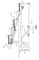
- FIG. 2 illustrates an example seating riser 12 A with a deck 16 A in a “stored” position. It should be understood that the riser 12 A is representative of the remainder of the risers in the seating system 10 . Further, many of the views (such as FIGS. 2-3 ) of the seating riser 12 A are side views, and therefore it should be understood that the structure in these view may be essentially mirrored on the opposite side of the seating riser 12 A.
- the riser 12 A includes a support 14 A configured to support a deck 16 A.
- the support 14 A includes lower and upper longitudinal supports 18 , 20 extending in the longitudinal direction L.
- the lower longitudinal support 18 is spaced apart from the upper longitudinal support 20 in a vertical direction V, which is normal to the longitudinal direction L.
- the upper longitudinal support 20 is supported in this example by a first vertical support 22 and first and second cross supports 24 , 26 .
- the lower longitudinal support 18 may include a plurality of rollers 28 (such as wheels), which are configured to allow the riser 12 A to deploy and retract relative to a ground surface or a track, as examples.
- FIG. 3 illustrates the riser 12 A with the deck 16 A in the “use” position.
- the deck 16 A When in the “use” position, the deck 16 A is aligned with a deck from an adjacent riser (that is also in the “use” position).
- a first support arm 30 extends between a first pivot J 1 provided relative to the first cross support 24 and a second pivot J 2 on a trolley 34 mounted to adjacent a rear of the deck 16 A.
- a third pivot J 3 is provided adjacent a forward end of the riser 12 A, between the upper longitudinal support 20 and the deck 16 A at a location forward of the first and second pivots J 1 , J 2 .
- the deck 16 A includes a deck stringer 36 , which defines a deck plane P. In the stored position ( FIG. 2 ), the deck plane P lies in substantially a true horizontal plane.
- the deck 16 A is configured to be tilted relative to this horizontal position, about the joint J 3 , in response to an actuator 38 .
- the actuator 38 is a linear actuator.
- the actuator 38 includes a motor 40 and a ball screw assembly 42 .
- the ball screw assembly 42 includes a ball screw 44 and a ball nut 46 (as seen in FIGS. 5-6 ).
- the ball screw 44 is mounted relative to the deck stringer 36 along an axis A.
- the axis A is substantially parallel to the plane P in this example.
- the ball screw 44 is configured to rotate in a direction R about the rotation axis A.
- the motor 40 is configured to lock the ball screw 44 in place, and prevent rotation thereof to lock the deck 16 A in position.
- the deck 16 A may cooperate with a separate lock to maintain the deck 16 A in the “use” and “stored” positions.
- the ball nut 46 is mounted relative to the trolley 34 such that the ball nut 46 is prevented from rotating about the axis A.
- rotation of the ball screw 44 relative to the ball nut 46 translates into linear movement of the ball nut 46 and, in turn, the trolley 34 along the axis A.
- the ball nut 46 is mounted relative to the trolley 34 such that the trolley 34 is guided along the deck stringer 36 by way of side rollers 48 and vertical rollers 50 . As the trolley 34 travels rearward along the axis A, the deck 16 A tilts about the joint J 3 and moves into the “use” position. While not illustrated, a control unit may be in communication (e.g., wirelessly or otherwise) with the actuator 38 to selectively control tilting of the deck 16 A.
- a bellows 52 (shown in FIG. 8 ), which is compressible along the axis A, may be placed around the ball screw 44 to prevent debris from interfering with the ball screw assembly 42 .
- the deck stringer 36 may include stoppers 54 , 56 configured to abut axial limiters 58 , 60 provided adjacent the axial ends of the trolley 34 to prevent movement of the deck 16 A beyond either the used position or the stored position.
- each riser may include additional actuators (e.g., in FIG. 4 , the riser 12 A is shown with two actuators 38 , 38 ′).
- Providing a tiltable deck such as that described above increases the availability of seating, while reducing the vertical storage space required to store the seating system.
- each riser may include more than one support bracket, as illustrated in the example of FIG. 10 , which includes five support brackets 62 A- 62 E.
- FIG. 11 illustrates a drive system 64 for use with the seating system 10 .
- the illustrated drive system 64 may be used with other seating systems, however.
- the lowest level riser 12 A includes a motor and gearbox 66 connected, by way of a shaft 68 , to two drive sprockets 70 , 72 on opposed lateral sides of the riser 12 A.
- the drive sprockets 70 , 72 each engage a respective belt 74 , 76 to drive the seating riser in the forward and rearward directions.
- the shaft 68 is configured to rotate the drive sprocket 70 about an axis X.
- two idler pulleys 78 , 80 are positioned vertically below the axis X, and provide tension relative to the belt 74 so that the belt sufficiently engages the sprocket 70 .
- the belt 74 is fixed in place by way of clamping blocks 82 ( FIG. 13 ) provided at each end of the belt 74 .
- FIGS. 12-13 illustrate one side of the riser 12 A
- the opposite side of the riser 12 A may include a similar drive-sprocket/belt/idler-pulley arrangement to that shown in FIGS. 12-13 .
- the clamping blocks 82 may be positioned at each end of each of the belts 74 , 76 to maintain tension in the belt 74 .
- FIGS. 14 illustrates the detail of one of the clamping blocks 82 . As illustrated, the belt 74 is clamped between plates 84 , 86 , and may be longitudinally adjusted by way of an adjuster 88 .
- the adjuster 88 includes a bolt having a threaded shaft 90 and a head 92 . Opposite the head 92 , the threaded shaft 90 is attached to a slotted plate 94 supporting the plates 84 , 86 .
- the slotted plate 94 includes longitudinal slots 96 receiving fasteners 98 .
- the length of the slots 96 is longer than the diameter of the shafts of the fasteners 98 , which allows longitudinal movement of the adjuster 88 . This movement in turn adjusts the tension in the belt 74 .
- the belts 74 may include teeth on one side thereof, to engage the drive sprocket 70 .
- the drive sprocket 70 may include notches corresponding to the teeth in the belt. This relationship may increase force transfer between the drive sprocket 70 and the belt 74 .
- seating system 10 may include a rack and pinion drive, a cogged wheel/slotted track drive, a continuous cable and rigid chain drive, to name a few.
Abstract
A seating system according to an exemplary aspect of the present disclosure includes, among other things, a riser including a tiltable deck. Another seating system according to the present disclosure includes, among other things, a drive system for moving a riser. The drive system includes a sprocket configured to engage a belt.
Description
This application is a continuation of prior U.S. application Ser. No. 14/529,574, filed Oct. 31, 2014, which claims the benefit of U.S. Provisional Application No. 61/901,065, filed Nov. 7, 2013. The '574 application and the '065 provisional application are herein incorporated by reference in their entirety.
Seating risers are often used in auditoriums, gymnasiums, stadiums, and event halls, as examples, to accommodate spectators on portable seats, such as folding chairs, or on seats that are affixed to the risers. Certain facilities may require seating risers that are capable of being moved between a retracted position for storage and a deployed position for use.
A seating system according to an exemplary aspect of the present disclosure includes, among other things, a riser including a tiltable deck.
Another seating system according to the present disclosure includes, among other things, a drive system for moving a riser. The drive system includes a sprocket configured to engage a belt.
The embodiments, examples and alternatives of the preceding paragraphs, the claims, or the following description and drawings, including any of their various aspects or respective individual features, may be taken independently or in any combination. Features described in connection with one embodiment are applicable to all embodiments, unless such features are incompatible.
The drawings can be briefly described as follows:
An example seating system 10 is illustrated across FIGS. 1A-1E . The example seating system 10 includes a plurality of telescopic seating risers 12A-12F configured to telescope relative to one another when moving in a longitudinal direction L between a rearward, retracted position (FIG. 1A ) and a forward, deployed position (FIG. 1B ). In most examples, the longitudinal direction L is substantially parallel to a floor surface and substantially perpendicular to a gravity plane.
In one example, the lowest level seating riser 12A is a powered seating riser including a drive assembly for driving the riser 12A between the deployed and retracted positions. The drive assembly may optionally laterally steer the risers 12A-12F during deployment and retraction. In another example, such as that discussed relative to FIGS. 11-14 , the risers 12A-12F deploy and retract along tracks. Movement of the lowest level riser 12A moves the remaining risers 12B-12F in series. While six seating risers 12A-12F are shown, it should be understood that this disclosure extends the seating systems with any number of risers, including systems with only a single riser.
Referring to FIG. 1C , each of the risers 12A-12F includes a support 14A-14F for supporting a deck 16A-16F. In this example, the decks 16A-16F each include a plurality of vertically stepped levels L1-L5 (see FIGS. 2-3 ). In one example, each of the levels L1-L5 includes a row of affixed seats. In other examples, however, the levels L1-L5 do not include fixed seats.
As will be explained below, the decks 16A-16F are tiltable between a “stored” position (FIGS. 1A-1B and FIG. 2 ) and a “use” position (FIGS. 1D-E and FIG. 3 ). FIG. 1C illustrates the decks 16A-16F between the “use” position and “stored” positions.
The riser 12A includes a support 14A configured to support a deck 16A. In this example, the support 14A includes lower and upper longitudinal supports 18, 20 extending in the longitudinal direction L. The lower longitudinal support 18 is spaced apart from the upper longitudinal support 20 in a vertical direction V, which is normal to the longitudinal direction L. The upper longitudinal support 20 is supported in this example by a first vertical support 22 and first and second cross supports 24, 26. The lower longitudinal support 18 may include a plurality of rollers 28 (such as wheels), which are configured to allow the riser 12A to deploy and retract relative to a ground surface or a track, as examples.
The deck 16A includes a deck stringer 36, which defines a deck plane P. In the stored position (FIG. 2 ), the deck plane P lies in substantially a true horizontal plane. The deck 16A is configured to be tilted relative to this horizontal position, about the joint J3, in response to an actuator 38.
The detail of the actuator 38 is illustrated in FIG. 4 . The actuator 38, in this example, is a linear actuator. The actuator 38 includes a motor 40 and a ball screw assembly 42. The ball screw assembly 42 includes a ball screw 44 and a ball nut 46 (as seen in FIGS. 5-6 ). The ball screw 44 is mounted relative to the deck stringer 36 along an axis A. The axis A is substantially parallel to the plane P in this example. Upon actuation of the motor 40, the ball screw 44 is configured to rotate in a direction R about the rotation axis A.
The motor 40 is configured to lock the ball screw 44 in place, and prevent rotation thereof to lock the deck 16A in position. In other examples, the deck 16A may cooperate with a separate lock to maintain the deck 16A in the “use” and “stored” positions.
As perhaps best seen in FIGS. 6-7 , the ball nut 46 is mounted relative to the trolley 34 such that the ball nut 46 is prevented from rotating about the axis A. Thus, rotation of the ball screw 44 relative to the ball nut 46 translates into linear movement of the ball nut 46 and, in turn, the trolley 34 along the axis A.
The ball nut 46 is mounted relative to the trolley 34 such that the trolley 34 is guided along the deck stringer 36 by way of side rollers 48 and vertical rollers 50. As the trolley 34 travels rearward along the axis A, the deck 16A tilts about the joint J3 and moves into the “use” position. While not illustrated, a control unit may be in communication (e.g., wirelessly or otherwise) with the actuator 38 to selectively control tilting of the deck 16A.
In order to protect the ball screw assembly 42, a bellows 52 (shown in FIG. 8 ), which is compressible along the axis A, may be placed around the ball screw 44 to prevent debris from interfering with the ball screw assembly 42.
Further, as shown in FIG. 8 , the deck stringer 36 may include stoppers 54, 56 configured to abut axial limiters 58, 60 provided adjacent the axial ends of the trolley 34 to prevent movement of the deck 16A beyond either the used position or the stored position.
While a particular actuator 38 has been illustrated and described herein, it should be understood that other types of actuators (e.g., linear actuators that do not include ballscrews, and non-linear actuators) come within the scope of this disclosure. Further, while only one actuator 38 has been described, each riser may include additional actuators (e.g., in FIG. 4 , the riser 12A is shown with two actuators 38, 38′).
Providing a tiltable deck such as that described above increases the availability of seating, while reducing the vertical storage space required to store the seating system.
As illustrated in FIGS. 9-10 , the lowest level L1 of the higher level deck 16B may be supported on a support bracket 62 extending upwardly, in the vertical direction V, relative to the highest level L5 of a lower level deck 16A for increased stability. Each riser may include more than one support bracket, as illustrated in the example of FIG. 10 , which includes five support brackets 62A-62E.
With reference to FIG. 12 , the arrangement between the drive sprocket 70 and the belt 74 is illustrated. In this example, the shaft 68 is configured to rotate the drive sprocket 70 about an axis X. Further, two idler pulleys 78, 80 are positioned vertically below the axis X, and provide tension relative to the belt 74 so that the belt sufficiently engages the sprocket 70. In this example, the belt 74 is fixed in place by way of clamping blocks 82 (FIG. 13 ) provided at each end of the belt 74. Thus, rotation of the sprocket 70 moves the lower level riser 12A in the forward and rearward directions along the belt 74. While FIGS. 12-13 illustrate one side of the riser 12A, the opposite side of the riser 12A may include a similar drive-sprocket/belt/idler-pulley arrangement to that shown in FIGS. 12-13 .
The clamping blocks 82 may be positioned at each end of each of the belts 74, 76 to maintain tension in the belt 74. FIGS. 14 illustrates the detail of one of the clamping blocks 82. As illustrated, the belt 74 is clamped between plates 84, 86, and may be longitudinally adjusted by way of an adjuster 88.
In this example, the adjuster 88 includes a bolt having a threaded shaft 90 and a head 92. Opposite the head 92, the threaded shaft 90 is attached to a slotted plate 94 supporting the plates 84, 86. The slotted plate 94 includes longitudinal slots 96 receiving fasteners 98. The length of the slots 96 is longer than the diameter of the shafts of the fasteners 98, which allows longitudinal movement of the adjuster 88. This movement in turn adjusts the tension in the belt 74.
While not illustrated herein, the belts 74 may include teeth on one side thereof, to engage the drive sprocket 70. The drive sprocket 70 may include notches corresponding to the teeth in the belt. This relationship may increase force transfer between the drive sprocket 70 and the belt 74.
While a particular drive system 64 is illustrated across FIGS. 11-14 , other drive systems may be included herein. For instance, seating system 10 may include a rack and pinion drive, a cogged wheel/slotted track drive, a continuous cable and rigid chain drive, to name a few.
Although the different examples have the specific components shown in the illustrations, embodiments of this disclosure are not limited to those particular combinations. It is possible to use some of the components or features from one of the examples in combination with features or components from another one of the examples.
One of ordinary skill in this art would understand that the above-described embodiments are exemplary and non-limiting. That is, modifications of this disclosure would come within the scope of the claims. Accordingly, the following claims should be studied to determine their true scope and content.
Claims (15)
1. A seating system, comprising:
a riser including a tiltable deck, wherein the deck is tiltable between a stored position and a use position, wherein the deck is substantially perpendicular to a gravity plane when in a stored position, and wherein, when in the use position, the deck is inclined at an acute angle relative to the position of the deck in the stored position, wherein the riser is one of a plurality of risers configured to telescope relative to one another.
2. The seating system as recited in claim 1 , further comprising an actuator operable to selectively tilt the deck.
3. The seating system as recited in claim 2 , wherein the deck tilts about a pivot adjacent a forward end of the riser.
4. The seating system as recited in claim 2 , wherein the actuator is mounted to a stringer supporting the deck.
5. A seating system, comprising:
a riser including a tillable deck, wherein the deck is tillable between a stored position and a use position, wherein the deck is substantially perpendicular to a gravity plane when in a stored position, and wherein, when in the use position, the deck is inclined at an acute angle relative to the position of the deck in the stored position; and
an actuator operable to selectively tilt the deck, wherein the actuator is mounted to a stringer supporting the deck, and wherein a support arm extends between the stringer and a riser support.
6. The seating system as recited in claim 5 , wherein the riser support is a cross support between a first longitudinal support and a second longitudinal support.
7. The seating system as recited in claim 6 , wherein the stringer is pivotably connected to the upper longitudinal support, the support arm is pivotably connected to the cross support, and the support arm is pivotably connected to the actuator.
8. A seating system, comprising:
a riser including a tiltable deck, wherein the deck is tiltable between a stored position and a use position, wherein the deck is substantially perpendicular to a gravity plane when in a stored position, and wherein, when in the use position, the deck is inclined at an acute angle relative to the position of the deck in the stored position; and
an actuator operable to selectively tilt the deck, wherein the deck tilts about a pivot adjacent a forward end of the riser, and wherein the actuator includes a motor operable to rotate a ball nut relative to a ball screw.
9. The seating system as recited in claim 8 , wherein rotation of the ball screw relative to the ball nut moves the ball nut along the length of a deck stringer.
10. The seating system as recited in claim 9 , wherein a trolley is connected to the ball nut, the trolley including a plurality of rollers configured to guide the trolley relative to the deck stringer.
11. The seating system as recited in claim 10 , wherein the deck stringer includes a first stopper and a second stopper, and wherein the trolley includes first and second limiters configured to engage the first and second stoppers to limit the movement of the deck.
12. A seating system, comprising:
a drive system for moving a riser, the drive system including a sprocket configured to engage a belt; and
a first clamping block and a second clamping block, the first and second clamping blocks provided adjacent respective ends of the belt;
wherein at least one of the first and second clamping blocks is configured to adjust a tension in the belt;
wherein the at least one of the first and second clamping blocks includes an upper plate and a lower plate, each of the upper and lower plates supported on a slotted plate having a plurality of slots therein, the slots allowing for movement of the slotted plate relative to a plurality of fasteners to adjust the tension in the belt.
13. The seating system as recited in claim 12 , wherein the drive system includes a motor operable to rotate the sprocket.
14. The seating system as recited in claim 12 , wherein the drive system includes a first idler pulley and a second idler pulley on opposed sides of the sprocket, each of the first and second idler pulleys configured to engage the belt.
15. The seating system as recited in claim 12 , wherein the riser includes a tiltable deck.
Priority Applications (1)
| Application Number | Priority Date | Filing Date | Title |
|---|---|---|---|
| US15/061,610 US9809987B2 (en) | 2013-11-07 | 2016-03-04 | Seating system with tiltable deck and belt drive |
Applications Claiming Priority (3)
| Application Number | Priority Date | Filing Date | Title |
|---|---|---|---|
| US201361901065P | 2013-11-07 | 2013-11-07 | |
| US14/529,574 US9332846B2 (en) | 2013-11-07 | 2014-10-31 | Seating system with tiltable deck and belt drive |
| US15/061,610 US9809987B2 (en) | 2013-11-07 | 2016-03-04 | Seating system with tiltable deck and belt drive |
Related Parent Applications (1)
| Application Number | Title | Priority Date | Filing Date |
|---|---|---|---|
| US14/529,574 Continuation US9332846B2 (en) | 2013-11-07 | 2014-10-31 | Seating system with tiltable deck and belt drive |
Publications (2)
| Publication Number | Publication Date |
|---|---|
| US20160186454A1 US20160186454A1 (en) | 2016-06-30 |
| US9809987B2 true US9809987B2 (en) | 2017-11-07 |
Family
ID=53005909
Family Applications (2)
| Application Number | Title | Priority Date | Filing Date |
|---|---|---|---|
| US14/529,574 Active 2034-11-09 US9332846B2 (en) | 2013-11-07 | 2014-10-31 | Seating system with tiltable deck and belt drive |
| US15/061,610 Active US9809987B2 (en) | 2013-11-07 | 2016-03-04 | Seating system with tiltable deck and belt drive |
Family Applications Before (1)
| Application Number | Title | Priority Date | Filing Date |
|---|---|---|---|
| US14/529,574 Active 2034-11-09 US9332846B2 (en) | 2013-11-07 | 2014-10-31 | Seating system with tiltable deck and belt drive |
Country Status (1)
| Country | Link |
|---|---|
| US (2) | US9332846B2 (en) |
Cited By (2)
| Publication number | Priority date | Publication date | Assignee | Title |
|---|---|---|---|---|
| US20150013236A1 (en) * | 2012-02-08 | 2015-01-15 | Steeldeck Industries Limited | Rostrum support structure |
| US20230003041A1 (en) * | 2016-10-19 | 2023-01-05 | Tait Towers Manufacturing, LLC | Theater having a modular auditorium and method for assembling a theater |
Families Citing this family (4)
| Publication number | Priority date | Publication date | Assignee | Title |
|---|---|---|---|---|
| WO2013016050A2 (en) * | 2011-07-22 | 2013-01-31 | Irwin Seating Company | Nosemount seating system |
| EP3335775A1 (en) * | 2016-12-19 | 2018-06-20 | Pierre Chican | Movie projection room suitable for large-screen projection |
| US11035138B2 (en) * | 2018-11-02 | 2021-06-15 | Hussey Seating Company | Bleacher deck interlock apparatus and method |
| WO2022087940A1 (en) * | 2020-10-29 | 2022-05-05 | 徐永顺 | Sports platform structure capable of simultaneously changing different inclination directions |
Citations (42)
| Publication number | Priority date | Publication date | Assignee | Title |
|---|---|---|---|---|
| US2183056A (en) | 1937-06-03 | 1939-12-12 | Fred Medart Mfg Company | Seating structure |
| US2449829A (en) * | 1945-03-17 | 1948-09-21 | Carl G Agren | Portable loading ramp |
| US2706835A (en) | 1951-03-01 | 1955-04-26 | Berlin Chapman Company | Retractable bleacher assemblage |
| US2968842A (en) | 1957-05-08 | 1961-01-24 | Fred Medart Mfg Co | Telescopic bleachers and motorized movers therefor |
| US2990587A (en) | 1959-03-20 | 1961-07-04 | Fred Medart Mfg Co | Power actuated movers for telescoping gymnasium seat-structures |
| US3222827A (en) | 1962-01-23 | 1965-12-14 | Playtime Equipment Corp | Grandstand construction |
| US3389511A (en) | 1966-03-08 | 1968-06-25 | Brunswick Corp | Telescoping gymnasium seating units |
| US3429081A (en) | 1964-08-20 | 1969-02-25 | Automatic Sprinkler Corp | Telescoping chair riser structure |
| US3667171A (en) | 1971-01-08 | 1972-06-06 | American Seating Co | Row folding seating structure |
| US3738612A (en) | 1971-05-04 | 1973-06-12 | American Seating Co | Advancing and retracting mechanism |
| US3743131A (en) | 1970-06-22 | 1973-07-03 | Dart Ind Inc | Closure for open-mouthed containers or tubular vessels |
| US3881140A (en) | 1974-03-01 | 1975-04-29 | American Seating Co | System for expanding and retracting telescoping seating row sections |
| US4041655A (en) | 1976-07-26 | 1977-08-16 | Universal Bleacher Company | Telescoping seating systems |
| US4155202A (en) | 1978-04-03 | 1979-05-22 | American Seating Company | Telescoping seating system with automatically folding chairs |
| US4189876A (en) | 1978-08-07 | 1980-02-26 | American Seating Company | Beam-mounted folding chairs |
| US4367612A (en) | 1980-04-14 | 1983-01-11 | Hussey Manufacturing Company | Composite supporting structure |
| US4490949A (en) | 1982-10-18 | 1985-01-01 | Hussey Manufacturing Company | Bench type seating modules |
| US4909000A (en) | 1988-12-02 | 1990-03-20 | Rollway Grandstand Corporation | Folding grandstand |
| US5069007A (en) | 1990-12-06 | 1991-12-03 | E. T. Paddock Enterprises, Inc. | Wheel channel guide-lock for gymnasium bleachers |
| US5517091A (en) | 1993-08-18 | 1996-05-14 | Charron Sports Services, Inc. | Modular electrical system for device units |
| US5660000A (en) | 1996-08-09 | 1997-08-26 | Macintyre; James R. | Movable two-fold seating assembly |
| US5921031A (en) | 1997-01-16 | 1999-07-13 | Williams; Arvel J. | Folding barrier for retractable sport bleachers |
| US5979125A (en) | 1996-02-09 | 1999-11-09 | Guillet S.A. | Foldable and mobile steps or bleachers structure |
| US6055780A (en) | 1997-05-26 | 2000-05-02 | Kotobuki Corporation | Retractable stairs-like stand |
| US6199325B1 (en) | 1999-03-02 | 2001-03-13 | Irwin Seating Company | Power system for extending and retracting a structure |
| US6293053B1 (en) | 1999-12-21 | 2001-09-25 | Specialty Supply & Installation | Non friction direct drive power system |
| US6324790B1 (en) | 1999-09-01 | 2001-12-04 | Interkal, Inc. | Deployable seating arrangement |
| US6415551B1 (en) | 1999-12-21 | 2002-07-09 | Specialty Supply & Installation Company | Non friction direct drive powered telescoping bleacher seating system |
| US20030009950A1 (en) | 2001-07-16 | 2003-01-16 | Hallberg Edwin A. | Telescopic seating riser assembly |
| US6625932B1 (en) | 1998-03-03 | 2003-09-30 | Dexter Littlefield | Variable rise vertically retractable arena seating assembly |
| US20040035060A1 (en) | 2002-08-23 | 2004-02-26 | Kunio Miyazaki | Moveable shelf and partitioning system |
| US6743131B1 (en) | 2000-10-10 | 2004-06-01 | Moxee Innovations Corporation | Single strap floating belt tensioner |
| US20040128918A1 (en) | 2002-11-06 | 2004-07-08 | Pai-Hsueh Yang | Control system and method for improving tracking accuracy of a stage through processing of information from previous operations |
| US20080083170A1 (en) | 2006-10-04 | 2008-04-10 | Kenneth Edward Staten | Powered dual level telescopic seating riser assembly |
| US20080190038A1 (en) | 2007-02-14 | 2008-08-14 | Track Corp. | Multi-configurable platform seating system |
| US20100183388A1 (en) | 2009-01-16 | 2010-07-22 | Foxnum Technology Co., Ltd. | Detecting system and method for cutting tools |
| US20100192477A1 (en) | 2009-01-30 | 2010-08-05 | Track Corp. | Multi-event telescopic platform |
| US20110016798A1 (en) | 2009-07-23 | 2011-01-27 | Jacobs Frederick D | Flexible Venue System |
| US20110099915A1 (en) | 2009-10-30 | 2011-05-05 | Irwin Seating Company | Bleacher seating system |
| US8484903B2 (en) * | 2010-12-10 | 2013-07-16 | Stageright Corporation | Seating system |
| US8528971B2 (en) | 2008-03-04 | 2013-09-10 | Hussey Seating Company | Seating spacers for seating systems |
| US20140259986A1 (en) * | 2013-03-15 | 2014-09-18 | The Will-Burt Company | Sliding locking actuator for automatic tilt mechanism |
-
2014
- 2014-10-31 US US14/529,574 patent/US9332846B2/en active Active
-
2016
- 2016-03-04 US US15/061,610 patent/US9809987B2/en active Active
Patent Citations (45)
| Publication number | Priority date | Publication date | Assignee | Title |
|---|---|---|---|---|
| US2183056A (en) | 1937-06-03 | 1939-12-12 | Fred Medart Mfg Company | Seating structure |
| US2449829A (en) * | 1945-03-17 | 1948-09-21 | Carl G Agren | Portable loading ramp |
| US2706835A (en) | 1951-03-01 | 1955-04-26 | Berlin Chapman Company | Retractable bleacher assemblage |
| US2968842A (en) | 1957-05-08 | 1961-01-24 | Fred Medart Mfg Co | Telescopic bleachers and motorized movers therefor |
| US2990587A (en) | 1959-03-20 | 1961-07-04 | Fred Medart Mfg Co | Power actuated movers for telescoping gymnasium seat-structures |
| US3222827A (en) | 1962-01-23 | 1965-12-14 | Playtime Equipment Corp | Grandstand construction |
| US3429081A (en) | 1964-08-20 | 1969-02-25 | Automatic Sprinkler Corp | Telescoping chair riser structure |
| US3389511A (en) | 1966-03-08 | 1968-06-25 | Brunswick Corp | Telescoping gymnasium seating units |
| US3743131A (en) | 1970-06-22 | 1973-07-03 | Dart Ind Inc | Closure for open-mouthed containers or tubular vessels |
| US3667171A (en) | 1971-01-08 | 1972-06-06 | American Seating Co | Row folding seating structure |
| US3738612A (en) | 1971-05-04 | 1973-06-12 | American Seating Co | Advancing and retracting mechanism |
| US3881140A (en) | 1974-03-01 | 1975-04-29 | American Seating Co | System for expanding and retracting telescoping seating row sections |
| US4041655A (en) | 1976-07-26 | 1977-08-16 | Universal Bleacher Company | Telescoping seating systems |
| US4155202A (en) | 1978-04-03 | 1979-05-22 | American Seating Company | Telescoping seating system with automatically folding chairs |
| US4189876A (en) | 1978-08-07 | 1980-02-26 | American Seating Company | Beam-mounted folding chairs |
| US4367612A (en) | 1980-04-14 | 1983-01-11 | Hussey Manufacturing Company | Composite supporting structure |
| US4490949A (en) | 1982-10-18 | 1985-01-01 | Hussey Manufacturing Company | Bench type seating modules |
| US4909000A (en) | 1988-12-02 | 1990-03-20 | Rollway Grandstand Corporation | Folding grandstand |
| US5069007A (en) | 1990-12-06 | 1991-12-03 | E. T. Paddock Enterprises, Inc. | Wheel channel guide-lock for gymnasium bleachers |
| US5517091A (en) | 1993-08-18 | 1996-05-14 | Charron Sports Services, Inc. | Modular electrical system for device units |
| US5979125A (en) | 1996-02-09 | 1999-11-09 | Guillet S.A. | Foldable and mobile steps or bleachers structure |
| US5660000A (en) | 1996-08-09 | 1997-08-26 | Macintyre; James R. | Movable two-fold seating assembly |
| US5921031A (en) | 1997-01-16 | 1999-07-13 | Williams; Arvel J. | Folding barrier for retractable sport bleachers |
| US6055780A (en) | 1997-05-26 | 2000-05-02 | Kotobuki Corporation | Retractable stairs-like stand |
| US6625932B1 (en) | 1998-03-03 | 2003-09-30 | Dexter Littlefield | Variable rise vertically retractable arena seating assembly |
| US6199325B1 (en) | 1999-03-02 | 2001-03-13 | Irwin Seating Company | Power system for extending and retracting a structure |
| US6324790B1 (en) | 1999-09-01 | 2001-12-04 | Interkal, Inc. | Deployable seating arrangement |
| US6293053B1 (en) | 1999-12-21 | 2001-09-25 | Specialty Supply & Installation | Non friction direct drive power system |
| US6415551B1 (en) | 1999-12-21 | 2002-07-09 | Specialty Supply & Installation Company | Non friction direct drive powered telescoping bleacher seating system |
| US6743131B1 (en) | 2000-10-10 | 2004-06-01 | Moxee Innovations Corporation | Single strap floating belt tensioner |
| US20030009950A1 (en) | 2001-07-16 | 2003-01-16 | Hallberg Edwin A. | Telescopic seating riser assembly |
| US20040035060A1 (en) | 2002-08-23 | 2004-02-26 | Kunio Miyazaki | Moveable shelf and partitioning system |
| US20040128918A1 (en) | 2002-11-06 | 2004-07-08 | Pai-Hsueh Yang | Control system and method for improving tracking accuracy of a stage through processing of information from previous operations |
| US20080083170A1 (en) | 2006-10-04 | 2008-04-10 | Kenneth Edward Staten | Powered dual level telescopic seating riser assembly |
| US7900402B2 (en) | 2006-10-04 | 2011-03-08 | Stageright Corporation | Powered dual level telescopic seating riser assembly |
| US20110107682A1 (en) | 2006-10-04 | 2011-05-12 | Kenneth Edward Staten | Powered telescopic seating riser assembly |
| US20080190038A1 (en) | 2007-02-14 | 2008-08-14 | Track Corp. | Multi-configurable platform seating system |
| US8528971B2 (en) | 2008-03-04 | 2013-09-10 | Hussey Seating Company | Seating spacers for seating systems |
| US20100183388A1 (en) | 2009-01-16 | 2010-07-22 | Foxnum Technology Co., Ltd. | Detecting system and method for cutting tools |
| US7986416B2 (en) | 2009-01-16 | 2011-07-26 | Foxnum Technology Co., Ltd. | Detecting system and method for cutting tools |
| US20100192477A1 (en) | 2009-01-30 | 2010-08-05 | Track Corp. | Multi-event telescopic platform |
| US20110016798A1 (en) | 2009-07-23 | 2011-01-27 | Jacobs Frederick D | Flexible Venue System |
| US20110099915A1 (en) | 2009-10-30 | 2011-05-05 | Irwin Seating Company | Bleacher seating system |
| US8484903B2 (en) * | 2010-12-10 | 2013-07-16 | Stageright Corporation | Seating system |
| US20140259986A1 (en) * | 2013-03-15 | 2014-09-18 | The Will-Burt Company | Sliding locking actuator for automatic tilt mechanism |
Cited By (4)
| Publication number | Priority date | Publication date | Assignee | Title |
|---|---|---|---|---|
| US20150013236A1 (en) * | 2012-02-08 | 2015-01-15 | Steeldeck Industries Limited | Rostrum support structure |
| US10202780B2 (en) * | 2012-02-08 | 2019-02-12 | Steeldeck Industries Limited | Rostrum support structure |
| US20230003041A1 (en) * | 2016-10-19 | 2023-01-05 | Tait Towers Manufacturing, LLC | Theater having a modular auditorium and method for assembling a theater |
| US11846116B2 (en) * | 2016-10-19 | 2023-12-19 | Tait Towers Manufacturing, LLC | Theater having a modular auditorium and method for assembling a theater |
Also Published As
| Publication number | Publication date |
|---|---|
| US20160186454A1 (en) | 2016-06-30 |
| US20150121771A1 (en) | 2015-05-07 |
| US9332846B2 (en) | 2016-05-10 |
Similar Documents
| Publication | Publication Date | Title |
|---|---|---|
| US9809987B2 (en) | Seating system with tiltable deck and belt drive | |
| US9194144B2 (en) | Seating system | |
| US9194145B2 (en) | Powered telescopic seating riser assembly | |
| US8944239B2 (en) | Conveyor apparatus for loading or unloading packages from shipping containers | |
| US10618752B2 (en) | Device for loading or unloading of a transport container | |
| JP6629871B2 (en) | Stair climber | |
| CN108025667A (en) | For transporting and manipulating heavy duty method and apparatus | |
| US20110192680A1 (en) | Adjustable tree stand | |
| US9790698B2 (en) | Seating system | |
| CN100567048C (en) | The vehicle support deck that suspends | |
| WO2009087357A1 (en) | Boat deployment and recovery | |
| US20180258660A1 (en) | Adjustable height platform | |
| JP4078393B2 (en) | Leg wheel moving device | |
| US6783010B1 (en) | Glass pane handling assembly | |
| CA2916558C (en) | Auto-rotating aisle rail system and methods | |
| EP1819547B1 (en) | Floating vehicle support deck | |
| JP4053693B2 (en) | Lift level lock device | |
| KR20170091942A (en) | The wheel module variable degrees of freedom | |
| US9326611B1 (en) | Portable bleacher with active descent and lift mechanism | |
| CA2854306A1 (en) | Conveyor apparatus for loading or unloading packages from shipping containers | |
| JP2017089274A (en) | Inclination variation drive mechanism for lift-type stand, and stand | |
| JP2017089275A (en) | Variation mechanism of stepped floor tip height of lift-type stand, and stand |
Legal Events
| Date | Code | Title | Description |
|---|---|---|---|
| STCF | Information on status: patent grant |
Free format text: PATENTED CASE |
|
| CC | Certificate of correction | ||
| MAFP | Maintenance fee payment |
Free format text: PAYMENT OF MAINTENANCE FEE, 4TH YR, SMALL ENTITY (ORIGINAL EVENT CODE: M2551); ENTITY STATUS OF PATENT OWNER: SMALL ENTITY Year of fee payment: 4 |