US9809676B2 - Automotive injection-molded product - Google Patents
Automotive injection-molded product Download PDFInfo
- Publication number
- US9809676B2 US9809676B2 US14/689,163 US201514689163A US9809676B2 US 9809676 B2 US9809676 B2 US 9809676B2 US 201514689163 A US201514689163 A US 201514689163A US 9809676 B2 US9809676 B2 US 9809676B2
- Authority
- US
- United States
- Prior art keywords
- injection
- molded product
- elements
- nozzle
- inlet port
- Prior art date
- Legal status (The legal status is an assumption and is not a legal conclusion. Google has not performed a legal analysis and makes no representation as to the accuracy of the status listed.)
- Expired - Fee Related
Links
Images


Classifications
-
- C—CHEMISTRY; METALLURGY
- C08—ORGANIC MACROMOLECULAR COMPOUNDS; THEIR PREPARATION OR CHEMICAL WORKING-UP; COMPOSITIONS BASED THEREON
- C08G—MACROMOLECULAR COMPOUNDS OBTAINED OTHERWISE THAN BY REACTIONS ONLY INVOLVING UNSATURATED CARBON-TO-CARBON BONDS
- C08G63/00—Macromolecular compounds obtained by reactions forming a carboxylic ester link in the main chain of the macromolecule
- C08G63/02—Polyesters derived from hydroxycarboxylic acids or from polycarboxylic acids and polyhydroxy compounds
- C08G63/12—Polyesters derived from hydroxycarboxylic acids or from polycarboxylic acids and polyhydroxy compounds derived from polycarboxylic acids and polyhydroxy compounds
- C08G63/123—Polyesters derived from hydroxycarboxylic acids or from polycarboxylic acids and polyhydroxy compounds derived from polycarboxylic acids and polyhydroxy compounds the acids or hydroxy compounds containing carbocyclic rings
- C08G63/127—Acids containing aromatic rings
-
- B—PERFORMING OPERATIONS; TRANSPORTING
- B29—WORKING OF PLASTICS; WORKING OF SUBSTANCES IN A PLASTIC STATE IN GENERAL
- B29C—SHAPING OR JOINING OF PLASTICS; SHAPING OF MATERIAL IN A PLASTIC STATE, NOT OTHERWISE PROVIDED FOR; AFTER-TREATMENT OF THE SHAPED PRODUCTS, e.g. REPAIRING
- B29C45/00—Injection moulding, i.e. forcing the required volume of moulding material through a nozzle into a closed mould; Apparatus therefor
- B29C45/16—Making multilayered or multicoloured articles
-
- B—PERFORMING OPERATIONS; TRANSPORTING
- B29—WORKING OF PLASTICS; WORKING OF SUBSTANCES IN A PLASTIC STATE IN GENERAL
- B29C—SHAPING OR JOINING OF PLASTICS; SHAPING OF MATERIAL IN A PLASTIC STATE, NOT OTHERWISE PROVIDED FOR; AFTER-TREATMENT OF THE SHAPED PRODUCTS, e.g. REPAIRING
- B29C45/00—Injection moulding, i.e. forcing the required volume of moulding material through a nozzle into a closed mould; Apparatus therefor
- B29C45/17—Component parts, details or accessories; Auxiliary operations
- B29C45/20—Injection nozzles
-
- B—PERFORMING OPERATIONS; TRANSPORTING
- B29—WORKING OF PLASTICS; WORKING OF SUBSTANCES IN A PLASTIC STATE IN GENERAL
- B29C—SHAPING OR JOINING OF PLASTICS; SHAPING OF MATERIAL IN A PLASTIC STATE, NOT OTHERWISE PROVIDED FOR; AFTER-TREATMENT OF THE SHAPED PRODUCTS, e.g. REPAIRING
- B29C45/00—Injection moulding, i.e. forcing the required volume of moulding material through a nozzle into a closed mould; Apparatus therefor
- B29C45/17—Component parts, details or accessories; Auxiliary operations
- B29C45/26—Moulds
- B29C45/27—Sprue channels ; Runner channels or runner nozzles
- B29C45/30—Flow control means disposed within the sprue channel, e.g. "torpedo" construction
- B29C2045/308—Mixing or stirring devices
-
- B—PERFORMING OPERATIONS; TRANSPORTING
- B29—WORKING OF PLASTICS; WORKING OF SUBSTANCES IN A PLASTIC STATE IN GENERAL
- B29K—INDEXING SCHEME ASSOCIATED WITH SUBCLASSES B29B, B29C OR B29D, RELATING TO MOULDING MATERIALS OR TO MATERIALS FOR MOULDS, REINFORCEMENTS, FILLERS OR PREFORMED PARTS, e.g. INSERTS
- B29K2067/00—Use of polyesters or derivatives thereof, as moulding material
- B29K2067/003—PET, i.e. poylethylene terephthalate
Definitions
- the present invention relates to an automotive injection-molded product molded using an injection molding nozzle.
- Japanese Examined Patent Application Publication No. 53-36182 proposes an injection molding nozzle used for kneading a material of an injection-molded product.
- the injection molding nozzle includes a nozzle body and a plurality of fluid mixing components.
- the nozzle body has a cylindrical shape, and has at its one end an inlet port through which a material is introduced and at its other end an outlet port through which the introduced material is delivered.
- the plurality of fluid mixing components is arranged between the inlet port and the outlet port of the nozzle body, and used for kneading a material which is introduced into the nozzle body through the inlet port by introducing the material through a plurality of fluid passages.
- natural pellets and masterbatches that color the natural pellets are introduced through the inlet port by an injection molding machine to flow through the plurality of fluid mixing components, and, thus, to be kneaded.
- the kneaded natural pellets and masterbatches are injected into a mold member through the outlet port, whereby injection molding is performed.
- a color difference between a high concentration portion and a low concentration portion of masterbatches with respect to natural pellets in a flat plate is more than 6.5.
- color unevenness may become accidentally noticeable.
- An object of the present invention is to provide an automotive injection-molded product where color unevenness is hardly noticeable.
- An automotive injection-molded product in accordance with some embodiments of the present invention includes natural pellets and masterbatches that color the natural pellets.
- a color difference between a high concentration portion and a low concentration portion of the masterbatches with respect to the natural pellets in a flat plate is not more than 6.5.
- the color difference between the high concentration portion and the low concentration portion with respect to the natural pellets in the flat plate is not more than 6.5, and therefore color unevenness is unnoticeable.
- the automotive injection-molded product may have a material physical property equivalent to a material physical property of colored pellets.
- the automotive injection-molded product has a material physical property substantially equivalent to that of colored pellets.
- the color unevenness is unnoticeable, and the material physical property is not lowered.
- the present inventor developed an injection molding nozzle which can achieve an injection pressure substantially equivalent to that of an open nozzle.
- the above-described automotive injection-molded product is molded using the injection molding nozzle.
- an automotive injection-molded product where color unevenness is hardly noticeable can be provided.
- FIG. 1 is a cross-sectional view of an injection molding nozzle according to a first study example.
- FIG. 2 is a front view of an element of the injection molding nozzle according to the first study example.
- FIG. 3 is a graph showing injection pressures in Examples and Comparative Examples in the injection molding nozzle according to the first study example.
- FIG. 4 is a side view of an injection molding nozzle according to a second study example.
- FIG. 5 is a front view of an element of the injection molding nozzle according to the second study example.
- FIG. 6 is a graph showing the injection pressures per one element in Examples and Comparative Examples in the injection molding nozzle according to the second study example.
- FIG. 7 is a view showing a relationship between an injection molding nozzle and a ratio between an element length and an element diameter and showing a range where the injection pressure can be reduced.
- FIG. 8 is a cross-sectional view of an injection molding nozzle according to a third study example.
- FIG. 9 is a front view of an element of the injection molding nozzle according to the third study example.
- FIG. 10 is a graph showing the injection pressures in Examples and Comparative Examples in the injection molding nozzle according to the third study example.
- FIG. 11 is a view showing a relationship between the number of element holes and a flow passage cross-sectional area in Examples and Comparative Examples in the injection molding nozzle according to the third study example.
- FIG. 12 is a graph of a reference example showing a change in a pressure loss per one element depending on changes in the element length and the element diameter.
- FIG. 13 is a graph of a reference example showing a change in the pressure loss per one element depending on a change in a land length.
- FIG. 14 is a graph showing measurement results of Examples and Comparative Examples when a resin of another example is used in natural pellets of an automotive injection-molded product according to an embodiment of the present invention.
- FIG. 15 is a view showing tensile breaking elongation of Examples and Comparative Examples when the resin of another example is used in the natural pellets of the automotive injection-molded product according to the embodiment of the present invention.
- FIG. 16 is a view showing Izod impact strength of Examples and Comparative Examples when the resin of another example is used in the natural pellets of the automotive injection-molded product according to the embodiment of the present invention.
- FIG. 17 is a view showing a color difference of Examples and Comparative Examples when the resin of another example is used in the natural pellets of the automotive injection-molded product according to the embodiment of the present invention.
- FIG. 18 is a graph showing determination results of Examples and Comparative Examples when the resin of another example is used in the natural pellets of the automotive injection-molded product according to the embodiment of the present invention.
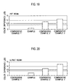
- FIG. 19 is a view showing the color difference of Examples and Comparative Examples in PBT resin of a reference example.
- FIG. 20 is a view showing the color difference of Examples and Comparative Examples in an m-PA6T resin of a reference example.
- FIGS. 1 to 13 study examples of an injection molding nozzle used for molding an automotive injection-molded product according to an embodiment of the present invention will be described using FIGS. 1 to 13 .
- the first study example will be described using FIGS. 1 to 3 .
- the injection molding nozzle 1 includes a nozzle body 7 and a plurality of elements 11 .
- the nozzle body 7 has a cylindrical shape, and has at its one end an inlet port 3 through which a fluid is introduced and at its other end an outlet port 5 through which the introduced fluid is delivered.
- the plurality of elements 11 is arranged between the inlet port 3 and the outlet port 5 of the nozzle body 7 , and used for kneading the fluid which is introduced into the nozzle body 7 through the inlet port 3 by introducing the fluid through a plurality of element holes 9 .
- the nozzle body 7 includes a pressure rise suppression part 13 which suppresses a rise of the injection pressure of the fluid introduced through the inlet port 3 .
- the number of the element holes 9 is set to two.
- the pressure rise suppression part 13 makes the injection pressure of a fluid, introduced through the inlet port 3 to pass through the plurality of elements 11 , and, thus, to flow through the outlet port 5 , substantially equivalent to the injection pressure of a fluid introduced through the inlet port 3 and directly flowing through the outlet port 5 , that is, a fluid flowing through an open nozzle.
- the nozzle body 7 has a cylindrical shape and includes the inlet port 3 and the outlet port 5 .
- the inlet port 3 is provided at one end of the nozzle body 7 and opens on the exterior side of the nozzle body 7 so as to communicate the outside and the inside of the nozzle body 7 .
- an injection molding machine (not shown) which injects a heated and melted molding resin material as a fluid is disposed on the inlet port 3 side.
- the molding resin material injected from the injection molding machine is introduced into the nozzle body 7 through the inlet port 3 at a predetermined injection pressure and then delivered through the outlet port 5 .
- a flow passage extending from the inlet port 3 toward the inside of the nozzle body 7 has a tapered shape so that the diameter is expanded toward the inside of the nozzle body 7 and reduces a pressure loss of the molding resin material introduced through the inlet port 3 .
- the outlet port 5 is provided at the other end of the nozzle body 7 and communicates the inside and the outside of the nozzle body 7 .
- a nozzle tip 15 is assembled, and the molding resin material is injected into a mold 17 through the nozzle tip 15 .
- the pressure loss of the molding resin material is further reduced by reducing the length of a distal end on the mold 17 side of the nozzle tip 15 .
- the molding resin material introduced through the inlet port 3 and then delivered through the outlet port 5 is sometimes colored by being mixed with other coloring materials.
- appearance failures such as color unevenness may occur.
- the plurality of elements 11 used for kneading melted molding resin materials is arranged between the inlet port 3 and the outlet port 5 of the nozzle body 7 .
- the plurality of (six in this case) elements 11 is arranged in parallel between the inlet port 3 and the outlet port 5 and each include a diverging part 19 and a mixing part 21 .
- the diverging part 19 is constituted of the plurality of element holes 9 communicated from the inlet port 3 side to the outlet port 5 side of an element body 23 .
- the element hole 9 includes a twisted blade 25 in which a base end on the inlet port 3 side and a base end on the outlet port 5 side are twisted at 180°.
- the molding resin material flowing through the one element hole 9 is divided into two flows. The flows of the molding resin material flowing through the plurality of element holes 9 is mixed by the mixing part 21 .
- the plurality of (six in this case) elements 11 is arranged in parallel between the inlet port 3 and the outlet port 5 , and the element body 23 has the two element holes 9 .
- the outer diameter is inscribed in the inner diameter of the element body 23 at equal intervals from the center of the element body 23 , and the element holes 9 are arranged at intervals of 180° in the circumferential direction of the element body 23 .
- the element holes 9 , 9 provided in the adjacent elements 11 , 11 are arranged while being shifted by 90° in the rotating direction where the center of the element body 23 is a rotation axis.
- the mixing parts 21 are provided respectively on the inlet port 3 side and the outlet port 5 side of the element body 23 and communicated with an entrance and an exit of the element hole 9 .
- the flows of the molding resin material flowing through the plurality of element holes 9 (in the element 11 closest to the inlet port 3 , the molding resin material introduced through the inlet port 3 ) converge and are mixed, and the mixed molding resin material is delivered into the plurality of element holes 9 of the element 11 located on the outlet port 5 side (in the element 11 closest to the outlet port 5 , the outlet port 5 ).
- the one element 11 has the two element holes 9 , and the division number per one element is four.
- the number of the element holes 9 in the one element 11 is set.
- the number of the element holes 9 in the one element 11 is set to two. In the number of the element holes 9 , the kneading efficiency is enhanced with an increase in the division number, and, in addition, the pressure loss is reduced with an increase in a flow passage cross-sectional area of the molding resin material.
- a diameter D 1 of the element 11 is set to not less than 2.5 times a diameter D 2 of the inlet port 3 .
- the diameter D 1 of the element 11 in the one element 11 is set in the pressure rise suppression part 13 which suppresses the rise of the injection pressure of the molding resin material introduced through the inlet port 3 of the nozzle body 7 .
- the diameter D 1 of the element 11 is set to not less than 2.5 times the diameter D 2 of the inlet port 3 .
- the flow passage cross-sectional area of the molding resin material is increased, so that the injection pressure can be made substantially equivalent to the injection pressure of an open nozzle.
- the diameter D 1 of the element 11 is set to not less than 2.5 times the diameter D 2 of the inlet port 3 .
- the flow passage cross-sectional area of the element 11 can be increased when a fluid flows inside an element 105 , and the pressure loss of the fluid flowing inside the nozzle body 7 can be reduced.
- the number of the element holes with respect to one element is two, and the number of the elements arranged in the nozzle body is six.
- Comparative Example 2 is an open nozzle in which no element is disposed between the inlet port and the outlet port.
- the diameter D 2 of the inlet port is 8 (mm)
- the diameter D 1 of the element is 19 (mm) in Examples 1 to 3, 20 (mm) in Example 4, and 16 (mm) in Comparative Example 1.
- the length L 1 of the element is 10 (mm) in Examples 1, 2, and 4, 30 (mm) in Example 3, and 15.5 (mm) in Comparative Example 1.
- the total of the land lengths L 2 and L 3 of the inlet port and the outlet port is 25 (mm) in Examples 1, 3, and 4, 30 (mm) in Example 2, 50 (mm) in Comparative Example 1, and 95 (mm) in Comparative Example 2.
- each Example according to the present invention exhibited the injection pressure substantially equivalent to that of Comparative Example 2 as an open nozzle.
- Comparative Example 1 having the diameter D 1 of the element that is less than 2.5 times the diameter D 2 of the inlet port exhibits such a very high injection pressure that it is increased by about 60% greater than Comparative Example 2.
- the flow passage cross-sectional area of a fluid in the element can be increased by increasing the diameter D 1 of the element, and a rise of the injection pressure can be suppressed.
- the injection pressure can be made substantially equivalent to the injection pressure of the open nozzle, and, in addition, an injection molding nozzle which can knead a fluid sufficiently can be obtained.
- a length L 1 (see, FIG. 1 ) of an element 105 is set to not less than 0.64 times and not more than 1.6 times a diameter D 3 of an element hole 9 .
- a plurality of (six in this case) the elements 105 is arranged in parallel between an inlet port 3 (see, FIG. 1 ) and an outlet port 5 (see, FIG. 1 ) in an axial direction of a nozzle body 7 .
- the element 105 has two element holes 9 .
- the outer diameter is inscribed in the inner diameter of the element 105 at equal intervals from the center of the element 105 , and the element holes 9 are arranged at intervals of 180° in the circumferential direction of the element 105 .
- the element holes 9 , 9 provided in the adjacent elements 105 , 105 are arranged while being shifted by 90° in the rotating direction where the center of the element 105 is a rotation axis.
- the inner diameter of the element 105 is a diameter D 1 of the element 105 .
- the injection molding nozzle 101 having the element 105 is disposed on the inner circumferential side of a locating ring insertion port 211 provided in a fixing board 209 of an injection molding machine.
- the locating ring insertion port 211 is disposed so that a center portion of a nozzle body 207 is positionally aligned with the central portion of the locating ring insertion port 211 , and a mold member like a mold 17 (see, FIG. 1 ) fixed by the fixing board 209 of the injection molding machine is inserted into the locating ring insertion port 211 on the outlet port 5 side and then fixed.
- the respective center positions of the mold member and the nozzle body 207 are positionally aligned with each other, and the molding resin material injected by a cylinder 213 of the injection molding machine is kneaded through the injection molding nozzle 101 and then injected into the mold member.
- a generally applied injection molding machine has a size of not more than 300 tons, and, at this time, a maximum value of a diameter D 4 of the locating ring insertion port 211 is 120 (mm). Thus, a maximum value of the diameter D 1 of an element 203 is set to 50.5 (mm).
- a heater disposed on the outer circumference of the nozzle body 207 is required to have a thickness of 8 (mm)
- a clearance between the nozzle body 207 and the locating ring insertion port 211 is required to be 10 (mm)
- the maximum value of the length of the installable nozzle body 207 is 200 (mm).
- the nozzle body 207 accommodates the six elements 105 .
- the maximum value of the length L 1 (see, FIG. 5 ) per the one element 105 is set to 20 (mm), considering the inlet port 3 (see, FIG. 1 ), the outlet port 5 (see, FIG. 1 ), or other clearances, and the like.
- a ratio between the length L 1 of the element 105 and the diameter D 3 of the element hole 9 (L 1 /D 3 ) is set.
- the setting of the ratio between the length L 1 of the element 105 and the diameter D 3 of the element hole 9 (L 1 /D 3 ) efficiently increases the flow passage cross-sectional area of the molding resin material in the element 105 .
- the pressure loss of the molding resin material flowing inside the nozzle body 207 can be reduced.
- the length L 1 of the element 105 is set to not less than 0.64 times and not more than 1.6 times the diameter D 3 of the element hole 9 .
- the length L 1 of the element was 16 (mm).
- the diameter D 3 of the element hole was 10 (mm) in Example 1, 11 (mm) in Example 2, 12 (mm) in Example 3, 13 (mm) in Example 4, 14.5 (mm) in Example 5, 15 (mm) in Example 6, 20 (mm) in Example 7, 25 (mm) in Example 8, 8 (mm) in Comparative Example 1, 9 (mm) in Comparative Example 2, and 35 (mm) in Comparative Example 3.
- FIG. 6 also shows a ratio between the length L 1 of the element and the diameter D 3 of the element hole (L 1 /D 3 ) and the diameter D 1 of the element.
- Example 8 according to the present invention exhibits a very small injection pressure as in Comparative Example 3, when the element hole (the element) has the diameter in Comparative Example 3, the element hole cannot be disposed in a locating ring insertion port having a diameter D 4 whose maximum value is 120 (mm), and therefore, Example 8 in which the element hole can be disposed is an upper limit of the diameter of the element hole.
- Example 1 according to the present invention has a diameter of the element hole (the element), which can be disposed in the locating ring insertion port having the diameter D 4 whose maximum value is not more than 120 (mm), as in Comparative Examples 1 and 2.
- the injection pressure may exceed the maximum injection pressure that is a performance upper limit of an injection molding machine, and molding cannot be performed when the injection pressure is the performance upper limit of the injection molding machine.
- Example 1 in which the injection pressure per one element was not more than 2.9 (MPa) was defined as a lower limit value.
- the element hole can be disposed in the locating ring insertion port, and the injection pressure was more reduced than the injection pressures in the conventional Comparative Examples 1 and 2.
- the injection pressure defined when the ratio L/D between the length L of the element and the diameter D of the element is changed will be described in distribution of the injection pressure defined when a flow passage diameter d of the element is a horizontal axis.
- a range of the ratio L/D of a flow passage diameter ⁇ 8 is 0.30 to 1.21
- a range of the ratio L/D of a flow passage diameter ⁇ 10 is 0.98 to 0.24
- a range of the ratio L/D of a flow passage diameter ⁇ 14 . 5 is 1.00 to 0.20
- a range of the ratio L/D of a flow passage diameter ⁇ 25 is 0.99 to 0.20.
- the ratio L/D is 1.21 (point a), in the low passage diameter ⁇ 10 , the ratio L/D is 0.78 to 0.88 (point b 1 to point b 2 ), in the low passage diameter ⁇ 14.5, the ratio L/D is 0.40 to 0.67 (point c 1 to point c 2 ), and in the low passage diameter ⁇ 25 , the ratio L/D is 0.20 to 0.40 (point e 1 to point e 2 ).
- a range where the injection pressure can be reduced is a range (a diagonal portion in FIG. 7 ) surrounded by the points a, b 1 , b 2 , c 1 , c 2 , e 1 , and e 2 .
- FIGS. 8 to 11 a pressure rise suppression part 205 in which the number of element holes 9 is set to not less than three and not more than nine will be described below using FIGS. 8 to 11 .
- This study example shows an example in which the four element holes 9 are provided.
- the same components as those of the first and second study examples are denoted by the same reference numerals, and description of their configurations and functions is omitted while referring to the first study example. Since the third study example has the same configuration as the first study example, the obtained effects are the same.
- the four element holes 9 are provided with respect to one element 203 .
- the injection pressure of a molding resin material introduced through an inlet port 3 is substantially equivalent to the injection pressure of a molding resin material flowing through an open nozzle.
- an injection molding nozzle 1 in which the elements 203 are arranged can sufficiently knead the molding resin material.
- each of the four element holes 9 the outer diameter is inscribed in the inner diameter of an element body 23 at equal intervals from the center of the element body 23 , and the element holes 9 are arranged at equal intervals in the circumferential direction of the element body 23 .
- the element holes 9 , 9 of the adjacent elements 203 , 203 are arranged while being shifted by 45° in the rotating direction where the center of the element body 23 is a rotation axis. Such arrangement of the element holes 9 can enhance kneading efficiency of the molding resin material.
- the injection molding nozzle 1 has, in the nozzle body 7 , the pressure rise suppression part 205 which suppresses the rise of the injection pressure of a fluid introduced through the inlet port 3 .
- the rise of the injection pressure of the fluid introduced through the inlet port 3 can be suppressed by the pressure rise suppression part 205 , so that the pressure loss of the fluid flowing inside the nozzle body 7 can be reduced.
- the rise of the injection pressure can be suppressed by the pressure rise suppression part 205 , an increase in the size of an injection molding machine can be suppressed.
- the number of the element holes 9 is set to not less than three and not more than nine.
- the number of times of division of a fluid flowing through the elements 203 can be increased, and the kneading efficiency of the fluid can be enhanced.
- the flow passage cross-sectional area of the element 203 can be increased when the fluid flows inside the element 203 , and the pressure loss of the fluid flowing inside the nozzle body 7 can be reduced.
- the pressure rise suppression part 205 makes the injection pressure of a fluid, introduced through the inlet port 3 to pass through the plurality of elements 203 , and, thus, to flow through the outlet port 5 , substantially equivalent to the injection pressure of a fluid introduced through the inlet port 3 and directly flowing through the outlet port 5 .
- the pressure rise suppression part 205 can makes the pressure loss substantially equivalent to the pressure loss of an open nozzle in which the plurality of elements 203 is not provided in the nozzle body 7 .
- the pressure loss is substantially equivalent to the pressure loss of the open nozzle, the fluid can be kneaded in the nozzle body 7 .
- the number of the element holes 9 is set to four.
- the flow passage cross-sectional area of the element 203 is increased, whereby the pressure loss can be made substantially equivalent to the pressure loss of the open nozzle.
- the number of the element holes with respect to one element was from three to nine in each Example 1, two in Comparative Example 1, and ten in Comparative Example 2.
- the outer diameter is inscribed in the inner diameter of the element at equal intervals from the center of the element, and the element holes are arranged at equal intervals in the circumferential direction of the element.
- Comparative Example 3 no element is disposed between an inlet port and an outlet port, and Comparative Example 3 is an open nozzle whose diameter from the inlet port to the outlet port is constant. Thus, the flow passage cross-sectional area in Comparative Example 3 has a smaller value than other Examples and Comparative Examples.
- FIG. 10 shows the flow passage cross-sectional area of a fluid and the number of times of division of the fluid in each Example and each Comparative Example.
- FIG. 11 shows a relationship between the element hole and the flow passage cross-sectional area.
- Comparative Example 2 having ten element holes per one element, the injection pressure was more increased than Comparative Example 1.
- Example 2 having the four element holes per one element exhibited the injection pressure substantially equivalent to the injection pressure of Comparative Example 3 as an open nozzle.
- the division numbers not less than 46656 (times) in each Example of the present invention are about 11 times the division number of in Comparative Example 1 (the number of the elements holes: 2, the number of the elements: 6) that is 4096 (times), and in the injection molding nozzle according to each Example of this invention, the kneadability that is about 11 times that of a conventional injection molding nozzles can be at least obtained.
- the flow passage cross-sectional area not less than 103.8 (mm 2 ) in each Example of this invention is larger than the flow passage cross-sectional area in Comparative Example 1 that is 100.5 (mm 2 ).
- a change in the pressure loss due to an element length is shown in a table of FIG. 12 .
- a change in the pressure loss due to land lengths of an inlet port and an outlet port is shown in a table of FIG. 13 .
- a diameter of an element is a radius
- the element lengths in element diameters of 10, 16, 20, 30, and 40 (mm) are changed respectively to 5, 10, 15.5, and 20 (mm)
- the pressure loss (MPa) per one element defined when the injection speed is 20, 50, or 80 (mm/sec) are shown in the table.
- a total of the land lengths of the inlet port and the outlet port is changed to 10, 15, 20, 25, 30, 35, 40, and 45 (mm), and the pressure loss (MPa) per one element defined when the injection speed is 20, 50, or 80 (mm/sec) are shown in the table.
- the resistance of a fluid flowing inside a nozzle body can be reduced by reducing the element length and the land lengths of the inlet port and the outlet port, and it is possible to obtain an injection molding nozzle which can suppress the rise of the injection pressure of the fluid introduced through the inlet port.
- the diameter of the element is set to not less than 2.5 times the diameter of the inlet port, this value shows a lower limit, and its upper limit depends on the nozzle body accommodating the element.
- the diameter of the nozzle body is set to a size capable of accommodating the element whose diameter is set to at least not less than 2.5 times the diameter of the inlet port.
- FIGS. 14 to 20 An automotive injection-molded product according to the embodiment of the present invention which is molded using the injection molding nozzle studied as above will be described below using FIGS. 14 to 20 .
- the automotive injection-molded product according to the embodiment is constituted of natural pellets and masterbatches that color the natural pellets.
- a color difference between a high concentration portion and a low concentration portion of the masterbatches with respect to the natural pellets in a flat plate is not more than 6.5.
- the automotive injection-molded product has a material physical property substantially equivalent to that of colored pellets.
- Example 14 the automotive injection-molded product according to the embodiment which is molded using the injection molding nozzle shown in the above study examples is described as Example, the colored pellets are described as Comparative Example 1, an injection-molded product molded using a conventional injection molding nozzle is described as Comparative Example 2, and an injection-molded product molded using an open nozzle is described as Comparative Example 3.
- a shape of a test piece to be used was ASTM #4 in accordance with ASTM D638.
- a test piece to be used had a shape of a thickness of 3.2 (mm) ⁇ a width of 12.5 (mm) ⁇ a length of 63.5 (mm) in accordance with ASTM D256.
- a test piece to be used in a color measurement test has a flat plate shape of 81.2 (mm) ⁇ 81.2 (mm) ⁇ 2 (mm).
- Color measurement conditions include a 45-0 degree system, a light source D65, and a 10 degree field of view.
- the high concentration portion (where no color unevenness occurs) and the low concentration portion (where color unevenness occurs) of the masterbatches with respect to the natural pellets in the flat plate were subjected to color measurement, and the color difference was calculated.
- FIGS. 14 to 18 show the results obtained when 1401X06 manufactured by Toray Industries, Inc. as the PBT resin was used in the natural pellets.
- each Example as the automotive injection-molded product according to this embodiment, the color difference was not more than 6.5.
- each Example had the tensile breaking elongation and the Izod impact strength substantially equivalent to those of Comparative Example 1 as colored pellets.
- the color difference between the high concentration portion and the low concentration portion of the masterbatches with respect to the natural pellets in the flat plate is not more than 6.5, and therefore color unevenness is unnoticeable.
- the automotive injection-molded product according to this embodiment has a material physical property substantially equivalent to that of colored pellets. Thus, the color unevenness is unnoticeable, and the material physical property is not lowered.
- Examples of automotive injection-molded products include a connector, a protector, J/B, and R/B.
Landscapes
- Engineering & Computer Science (AREA)
- Manufacturing & Machinery (AREA)
- Mechanical Engineering (AREA)
- Chemical & Material Sciences (AREA)
- Health & Medical Sciences (AREA)
- Chemical Kinetics & Catalysis (AREA)
- Medicinal Chemistry (AREA)
- Polymers & Plastics (AREA)
- Organic Chemistry (AREA)
- Injection Moulding Of Plastics Or The Like (AREA)
Abstract
Description
Claims (16)
Applications Claiming Priority (3)
| Application Number | Priority Date | Filing Date | Title |
|---|---|---|---|
| JP2012-234219 | 2012-10-23 | ||
| JP2012234219 | 2012-10-23 | ||
| PCT/JP2013/078348 WO2014065216A1 (en) | 2012-10-23 | 2013-10-18 | Automotive injection-molded product |
Related Parent Applications (1)
| Application Number | Title | Priority Date | Filing Date |
|---|---|---|---|
| PCT/JP2013/078348 Continuation WO2014065216A1 (en) | 2012-10-23 | 2013-10-18 | Automotive injection-molded product |
Publications (2)
| Publication Number | Publication Date |
|---|---|
| US20150218307A1 US20150218307A1 (en) | 2015-08-06 |
| US9809676B2 true US9809676B2 (en) | 2017-11-07 |
Family
ID=50544596
Family Applications (1)
| Application Number | Title | Priority Date | Filing Date |
|---|---|---|---|
| US14/689,163 Expired - Fee Related US9809676B2 (en) | 2012-10-23 | 2015-04-17 | Automotive injection-molded product |
Country Status (4)
| Country | Link |
|---|---|
| US (1) | US9809676B2 (en) |
| JP (1) | JP2014100912A (en) |
| CN (1) | CN104755245B (en) |
| WO (1) | WO2014065216A1 (en) |
Families Citing this family (1)
| Publication number | Priority date | Publication date | Assignee | Title |
|---|---|---|---|---|
| JP6068926B2 (en) * | 2012-10-23 | 2017-01-25 | 矢崎総業株式会社 | Injection molding nozzle |
Citations (13)
| Publication number | Priority date | Publication date | Assignee | Title |
|---|---|---|---|---|
| JPS5336182A (en) | 1976-09-16 | 1978-04-04 | Hitachi Ltd | Thin semiconductor single crystal film forming insulation substrate |
| JPS5390063U (en) | 1976-12-25 | 1978-07-24 | ||
| JPS5789935A (en) | 1980-11-26 | 1982-06-04 | Akira Takeda | Mixer for injection molding machine |
| JPS59204520A (en) | 1983-05-09 | 1984-11-19 | Toshiba Corp | Resin kneading apparatus |
| JPS63122513A (en) | 1986-11-13 | 1988-05-26 | Toshiba Mach Co Ltd | High-dispersion screw for injection molding |
| JPH0292604A (en) | 1988-09-30 | 1990-04-03 | Nissan Motor Co Ltd | Resin part |
| JPH106364A (en) | 1996-06-21 | 1998-01-13 | Denki Kagaku Kogyo Kk | Production of molded product |
| JP2000198859A (en) | 1999-01-06 | 2000-07-18 | Techno Polymer Kk | Production of colored thermoplastic resin molded product and colored thermoplastic resin molded product |
| JP2001150474A (en) | 1999-11-30 | 2001-06-05 | Daihatsu Motor Co Ltd | Injection molding method, injection-molded molding, and master batch |
| JP2005178146A (en) | 2003-12-18 | 2005-07-07 | Calp Corp | Molding method for automotive parts |
| JP2006159609A (en) | 2004-12-07 | 2006-06-22 | Ube Machinery Corporation Ltd | Injection molding nozzle |
| CN101716812A (en) | 2009-12-01 | 2010-06-02 | 苏州奔腾塑业有限公司 | Injection molding nozzle |
| US8513344B2 (en) * | 2008-11-21 | 2013-08-20 | Toyo Aluminium Kabushiki Kaisha | Masterbatch for coloring synthetic resin |
-
2013
- 2013-10-18 CN CN201380055156.3A patent/CN104755245B/en not_active Expired - Fee Related
- 2013-10-18 WO PCT/JP2013/078348 patent/WO2014065216A1/en not_active Ceased
- 2013-10-23 JP JP2013219975A patent/JP2014100912A/en not_active Abandoned
-
2015
- 2015-04-17 US US14/689,163 patent/US9809676B2/en not_active Expired - Fee Related
Patent Citations (13)
| Publication number | Priority date | Publication date | Assignee | Title |
|---|---|---|---|---|
| JPS5336182A (en) | 1976-09-16 | 1978-04-04 | Hitachi Ltd | Thin semiconductor single crystal film forming insulation substrate |
| JPS5390063U (en) | 1976-12-25 | 1978-07-24 | ||
| JPS5789935A (en) | 1980-11-26 | 1982-06-04 | Akira Takeda | Mixer for injection molding machine |
| JPS59204520A (en) | 1983-05-09 | 1984-11-19 | Toshiba Corp | Resin kneading apparatus |
| JPS63122513A (en) | 1986-11-13 | 1988-05-26 | Toshiba Mach Co Ltd | High-dispersion screw for injection molding |
| JPH0292604A (en) | 1988-09-30 | 1990-04-03 | Nissan Motor Co Ltd | Resin part |
| JPH106364A (en) | 1996-06-21 | 1998-01-13 | Denki Kagaku Kogyo Kk | Production of molded product |
| JP2000198859A (en) | 1999-01-06 | 2000-07-18 | Techno Polymer Kk | Production of colored thermoplastic resin molded product and colored thermoplastic resin molded product |
| JP2001150474A (en) | 1999-11-30 | 2001-06-05 | Daihatsu Motor Co Ltd | Injection molding method, injection-molded molding, and master batch |
| JP2005178146A (en) | 2003-12-18 | 2005-07-07 | Calp Corp | Molding method for automotive parts |
| JP2006159609A (en) | 2004-12-07 | 2006-06-22 | Ube Machinery Corporation Ltd | Injection molding nozzle |
| US8513344B2 (en) * | 2008-11-21 | 2013-08-20 | Toyo Aluminium Kabushiki Kaisha | Masterbatch for coloring synthetic resin |
| CN101716812A (en) | 2009-12-01 | 2010-06-02 | 苏州奔腾塑业有限公司 | Injection molding nozzle |
Non-Patent Citations (7)
| Title |
|---|
| Chinese Office action dated Jul. 6, 2017 in the counterpart Chinese patent application. |
| Chinese Official Action dated Mar. 20, 2017 in the counterpart Chinese patent application. |
| Chinese Official Action dated Sep. 8, 2016 in the counterpart Chinese patent application. |
| Online translation of Detailed Description of JP 10-006364A; publication date: Jan. 1998. * |
| The Chinese office action dated Feb. 26, 2016 in the counterpart Chinese patent application. |
| The Official Action dated May 30, 2017 in the counterpart Japanese patent application. |
| Zhang Jiamin et al., Technique of Molding Plastics and Typical Technology Instance, Jul. 31, 2010, pp. 125-126, Chemical industry publishing house, China. |
Also Published As
| Publication number | Publication date |
|---|---|
| JP2014100912A (en) | 2014-06-05 |
| CN104755245B (en) | 2017-11-28 |
| US20150218307A1 (en) | 2015-08-06 |
| CN104755245A (en) | 2015-07-01 |
| WO2014065216A1 (en) | 2014-05-01 |
Similar Documents
| Publication | Publication Date | Title |
|---|---|---|
| CA2779844C (en) | Solid cone nozzle | |
| DE102007009282B4 (en) | combustion chamber | |
| CA2409529C (en) | Combustor containing fuel nozzle | |
| US7896644B2 (en) | Nozzle assembly for an injector | |
| US6899453B2 (en) | Static mixer and method for mixing a main component with an additive | |
| JP5731658B2 (en) | Mold system with a melt diverter comprising a continuous melt channel extending from the inlet to the outlet | |
| DE102007008993A1 (en) | burner | |
| US9809676B2 (en) | Automotive injection-molded product | |
| CN104755246B (en) | injection molding nozzle | |
| DE102019217830A1 (en) | COMBUSTION CHAMBER AND GAS TURBINE | |
| KR101479796B1 (en) | Inline Mixer Device | |
| CN106715888A (en) | Nozzle plate for fuel injection devices | |
| US20110026359A1 (en) | Mixing system for two-component cartridge | |
| KR102154396B1 (en) | injection devices for fluid | |
| JP3922778B2 (en) | Injection molding method and apparatus and valve pin | |
| WO2016111149A1 (en) | Nozzle plate for fuel injection device | |
| JP2006297670A (en) | Torpedo and flow path connection structure of injection molding machine | |
| KR102797088B1 (en) | Ultra-high pressure homogenizer | |
| KR20210042053A (en) | System for unstructured color mixing injection molding | |
| KR101221402B1 (en) | High density blending system | |
| KR102812194B1 (en) | Nozzle assembly, nozzle unit and ultra-high perssure homogenizer having the same | |
| KR100776388B1 (en) | Manifold assembly with drop tip and drop tip | |
| JP7243137B2 (en) | Ejector | |
| US20190337491A1 (en) | Fluid apparatus and nozzle | |
| KR20180092047A (en) | Mixing nozzle for injection and extrusion |
Legal Events
| Date | Code | Title | Description |
|---|---|---|---|
| AS | Assignment |
Owner name: YAZAKI CORPORATION, JAPAN Free format text: ASSIGNMENT OF ASSIGNORS INTEREST;ASSIGNORS:HANMURA, KAORU;KAYAMA, SHINOBU;REEL/FRAME:035433/0570 Effective date: 20150325 |
|
| STCF | Information on status: patent grant |
Free format text: PATENTED CASE |
|
| MAFP | Maintenance fee payment |
Free format text: PAYMENT OF MAINTENANCE FEE, 4TH YEAR, LARGE ENTITY (ORIGINAL EVENT CODE: M1551); ENTITY STATUS OF PATENT OWNER: LARGE ENTITY Year of fee payment: 4 |
|
| AS | Assignment |
Owner name: YAZAKI CORPORATION, JAPAN Free format text: CHANGE OF ADDRESS;ASSIGNOR:YAZAKI CORPORATION;REEL/FRAME:063845/0802 Effective date: 20230331 |
|
| FEPP | Fee payment procedure |
Free format text: MAINTENANCE FEE REMINDER MAILED (ORIGINAL EVENT CODE: REM.); ENTITY STATUS OF PATENT OWNER: LARGE ENTITY |
|
| LAPS | Lapse for failure to pay maintenance fees |
Free format text: PATENT EXPIRED FOR FAILURE TO PAY MAINTENANCE FEES (ORIGINAL EVENT CODE: EXP.); ENTITY STATUS OF PATENT OWNER: LARGE ENTITY |
|
| STCH | Information on status: patent discontinuation |
Free format text: PATENT EXPIRED DUE TO NONPAYMENT OF MAINTENANCE FEES UNDER 37 CFR 1.362 |
|
| FP | Lapsed due to failure to pay maintenance fee |
Effective date: 20251107 |