US980482A - Thrust-bearing. - Google Patents
Thrust-bearing. Download PDFInfo
- Publication number
- US980482A US980482A US48578309A US1909485783A US980482A US 980482 A US980482 A US 980482A US 48578309 A US48578309 A US 48578309A US 1909485783 A US1909485783 A US 1909485783A US 980482 A US980482 A US 980482A
- Authority
- US
- United States
- Prior art keywords
- shaft
- thrust
- collars
- carried
- sleeve
- Prior art date
- Legal status (The legal status is an assumption and is not a legal conclusion. Google has not performed a legal analysis and makes no representation as to the accuracy of the status listed.)
- Expired - Lifetime
Links
Images

Classifications
-
- F—MECHANICAL ENGINEERING; LIGHTING; HEATING; WEAPONS; BLASTING
- F16—ENGINEERING ELEMENTS AND UNITS; GENERAL MEASURES FOR PRODUCING AND MAINTAINING EFFECTIVE FUNCTIONING OF MACHINES OR INSTALLATIONS; THERMAL INSULATION IN GENERAL
- F16C—SHAFTS; FLEXIBLE SHAFTS; ELEMENTS OR CRANKSHAFT MECHANISMS; ROTARY BODIES OTHER THAN GEARING ELEMENTS; BEARINGS
- F16C19/00—Bearings with rolling contact, for exclusively rotary movement
- F16C19/22—Bearings with rolling contact, for exclusively rotary movement with bearing rollers essentially of the same size in one or more circular rows, e.g. needle bearings
- F16C19/30—Bearings with rolling contact, for exclusively rotary movement with bearing rollers essentially of the same size in one or more circular rows, e.g. needle bearings for axial load mainly
Definitions
- the present invention relates to thrust bearings and more especially to those Aintended for turbine driven apparatus and has forits object to improve their construction.
- Figure 1 is an arial section of shaft and thrust bearings
- Fig. 2 is a cross-sectional view of the same taken on line 2 2 of Fig. 1
- Fig.i3 is a cross-sectional view taken on line 3-3 of Fig. 1
- Fig. "4 is a perspective view 'showing the thrustcollars and spacers.
- This pillow block indicates the pillow block that is suit- Aably supported from a bed-plate or other means.
- This pillow block is provided with e a spherical surfacedse'at 6. Itis also proi vided with a removable head 7 that has a.
- the head 7 is secured in place by a number of stud bolts and may be made in 'one piece or split as desired.
- the pillo-w block may be provided with a removable cap vor may be made solid as desired.
- a tubular member 10 having an enlargement 11 which is provided with a spherical surface, this surface being struck from the same center as the spherical Vsurfaced seat.
- the diameter of the enlargement of the member 10 is somewhat less than the openin in the pillow block that receives the shoulder 8 on the head.
- 'trbular member is a concentric sleeve 12 that is provided with a babbitt lining 13, the latter forming the bearing surface for supporting the shaft 14.
- the sleeve 12 is slipped into place in the tubular member from the right-.hand side and is held against axial movement by the shoulder 15 and the bolt 1,6, the latter bein carried by the tubular member and provi ed with an extension that enters a hole in the sleeve.
- the sleeve and lining are cut away at a central point to receive the oil ring 17, the latter extending into the well 18.
- the pillow block is provided with a chamber 19 that may or may not be filled with oil as desired.
- Oil may be supplied tothe bearing under pressure by the passage 20 formed in the pillow block and the Yp ⁇ assages'21 and 22 formed in the tubular member and' the bearing sleeve.
- an annular chamber 23 is provided within which is located an oil thrower 24, the latter being carried by a shoulder on the shaft.
- the chamber 23 is or may be connected by one or more passages with the chamber 19 in the base of the pillow block, as indicated by the dotted line.
- a batller 25 is provided that consists of an annular member having a series of internal grooves. The baffler.
- a shield-plate 26 may be employed. Lubricant may be introduced intoy the bearing through the opening 27, and the passage 20 used as a drain.
- the left hand portion of the tubular member is bored to receive the concentric sleeve 28.
- This sleeve is prevented from rotating by the spline 29 but may be'adjusted longitudinally.
- the right hand end of the sleeve is provided with an internal flange or shoulder 30 that acts as a fixed abutment or stop forthe stationary thrust collars 31 held against rotation by the spline 31,of which collars as many may be provided as it is desired.
- Between the stationary thrust collars are stationary s acers 32 made in the form of rings.
- the le t hand end of the sleeve is threaded internally to receive the nut 33, the latter serving to clamp the stationary thrust collars and the spacers securely in place against the shoulder 30.
- the rotating thrust collars andspacers are held in place by a nut 39 that is mounted on the end of the shaft. By screwing the nut into place the parts are clamped between it and the shoulder ⁇ 34.
- All of the stationary thrust collars are of l the same thickness .so that they can be ground at one setting o n a grinding ma chine, thereby insuring exact uniformity.
- the fixed and revolvlng spaces are all of thesame thickness so that they can be yground at one setting. This construction insures absolute uniformity as to dimensions of as many cells'or units ⁇ as it ma y be desir-l able' to use.
- the thrust load 1s divided equally between theseveral cells or units, ex-
- Inla structure of this character it is highl desirable to be ⁇ able to adjust the longitudinal position of the shaft in order to ixthe clearances between the moving'parts eitherl on the turbine or on-the apparatus driven Ainsure freedom of operation, The clamping to the sta- In they ⁇ other means.
- the nut 33 is bored centrally to receive the adjustingscrew andthe nut is prevented from turning independently of the vcollar supporting sleeve 28 by means of one or more screws 45.
- the nut maybe provlded with a number of screwreceiving openings so that the nut can'be moved a sllght amount in either dlrection and afterward be clamped in place by the screw 45.
- the end of the adjusting screw' 43 is squared to receive a wrench. It is also provided with a nut -46 by means of which the collar 44 is firmly held against the part ⁇ 40 of thehead.
- the tubular member which carries the stationary part of vthe thrust bearing has the same center of movement as does the shaft bearing. This means that no matter how much the shaft may be deflected, due to inaccuracies in alinement, spring-ing of the shaft, or sudden" changes in load, that the thrust collars. will also be moved and that they will at all times b'e held with their working faces perpendicular to the axis ofthe shaft. It -is evident that whatever force causes the shaft to be deiected it will correspondingly change the position of its bearing and with it thejposition ofthe parts of the ,thrust bearing. v
- a support having a spherical surfaced seat, a self-alining member carried thereby ⁇ and comprising an cu.
- thrust collars carried by the tubular eXtension and also by the shaft which areat all times maintained perpendicular to the shaft axis.
- a pillow block having a spherical surfaced seat, a self-'alining member carried thereby and comprising an enlargement movable on the seat and a tubular extension that projects outside yof and the shaft carried bythe enlargement and adjustable withit, said bearing extending substantially the entire a-Xial length of the enlargement, thrust means carried by the shaft, other thrust means carried by the tubular extension and cooperating with those on the shaft, and means for adjusting the shaft and the thrust means longitudinally.
- a pillow block having a spherical surfaced seat, a self alining member carried thereby and movable on the seat, a bearing for the shaft carried by said member and adjustable with it, a plurality of thrust collars mou ted on the shaft, 'a plurality 'of thrust co lars carried by said member, clamping means for said collars,
- Ya support having a spherical surfaced seat, a selfalining member carried thereby and comprising an enlargement movable on the seat and a tubular portion eXtending'out-side of the support,
- a support having a spherical surfacedfseat, a sel alining member carried thereby and movable on the seat, a shaft, thrust collars supported by the member, other thrust collars supported by and turning with the shaft, spacers located between the stationary and also between the rotary thrust collars, and rolling means located between the collars for transmitting the thrust of the shaft to said member.
- a support having a spherical surfaced seat; a self alining meml ber carried thereby and movable on the seat,
- a support having a spherical surfaced seata self alining member carried thereby and movable on the seat, a shaft, a sleeve located within said member and supportedthereby, thrust collarsm'ounted in the sleeve, other thrust collars mounted on the shaft, a means for clamping the collars carried by-the sleeve, other means for clamping the collars carried by the shaft, and a means carried by the tubular member fori adjusting the position of the sleeve.
- aA sup ort having a spherical surfaced seat a sel alining member carried thereby an movable on the seat,
- a sleeve located within said member and supported thereby, thrust collars mounted in thesleeve, other thrust collars mounted vonl the shaft, a nut screw-threaded to the sleeve for clamping the stationary thrust collars, ⁇ a Y nut andvshoulder on the shaft for clamping the rotary thrust collars, rolling means located between the stationary and rotary eollars for transmitting the thrust of the shaft to said member, and an adjusting screw for s I adjusting the position of the sleeve in said member.
- a support having'a spherical surfaced seat, a self-alining tubularmember carriedthereby and movable on j the seat, a shaft, a sleeve splined inthe memf ber, stationary thrust collars carried by the sleeve, other collars carried by the shaft, spacers between both sets of collars, a clamp for securing the stationary collars and spacers, a clamp for securing the rotary collars and spacers on the shaft, rolling means Ylocated between the collars, and an adjusting screw that is anchored in the tubular member and engages a part of the clamp for moving the sleeve bodily to and fro.
- a support having a spherical surfaced seat, a self-alining tubular' member carried thereby and movable onthe seat, a shaft, a sleeve s lined in the mem? ber, stationary thrust co lars carried by the sleeve, other collars carried by the shaft, spacers between both sets of collars, a cla-m for securing the stationary collars and spacers, a clamp for securin the rotary collars and spacers on thesha t, rolling means located between the collars, a divided head for one end of the tubular member, and an adjustingscrew that has a collar located bctween and confined by the parts of the head., one end of said screw being threaded into the clamp.
- a' support having a spherical surfaced seat, a detachable YVhead therefor that is attached to the side of the support and forms a part of the seat and has a centering shoulder that is larger in dia1neter than the spherical surfaced. portion of 10l the' support, a series of thrust absorbing collars which may also be removed from one lthe ⁇ tubular member, a tubular member hav- ,if ing a spherical surfaced portion that en- ⁇ gages the seat and is held solely by it against Vaxlal movement and thrust collars carried 5 by the shaft and said member respectively.
- a support havin a spherical surfaced seat, a shaft, a self a inl ing member carried'thereby ⁇ 'which may be removed from the shaft by an endwise movement, a means for securing the member in' 20 member having an enlargement that engages -theseat, a parallel'bearin for the shaft carried by the member, a tu ular extension on said member, fixed collars carried by the shaft, xed collars carried by the tubular extension at one side A spline saone@ of said bearing, and' rollingv means located between the collars to transmit end thrust of the shaft in either direction to' the collars carried .by said member.
- a support having a seat, a member supported thereby and held l against axial movement,r said member includin a tubular extension, a sleevethat is g in the extension and is rovided at one end with an internal shoullder and at the'other end withl a screw thread, ⁇ collars mounted on the shaft and clamped against endvvise movement thereon, collars mounted in the sleeve, one of which engages the shoulder, ahead threaded to the sleeve for holding the collars carried thereby, and rollers between'the collars. 4
Landscapes
- Engineering & Computer Science (AREA)
- General Engineering & Computer Science (AREA)
- Mechanical Engineering (AREA)
- Support Of The Bearing (AREA)
Description
' F.R.C.B0YD. THRUST BEARING.
APPLICATION FILED MAB. 25, 1909.
Patented Jan. 3,1911.
2 SHEETS-BHEET 14 I Inventor; F-redelic/ C. Boyd, @E qtclj.
/m/Lm @dw F. R. C. BOYD.
THRUST BEARING. APPLICATION FILED MAR. 25, 1909.
980,423.2.l Patented Jan. 3, i911;
. 2;* 29 I 2 SHEETS-SHEET 2.
` Y 4 v l Witnesses: Ir'IVerltor; Frederic F?. C. Boyd,
escasa.
i" To. all whom 'it may concern:
Unten sTATss PATENT onirica.
FREDERIC R. BOYD, OE LYNN, MASSACHUSETTS, ASSIGNOR TO GENERAL ELECTRIC v COMYANY, A CORPORATION 0F NEW YORK.
Be it kno-'wn that I, FREDERIC R. C. BOYD, a citizen of the United States, residing at Lynn, county of Essex, State of Massachu-v setts, have invented certain new and useful Improvements in Thrust-Bearings, of which the following is a specilication. l
The present invention relates to thrust bearings and more especially to those Aintended for turbine driven apparatus and has forits object to improve their construction. For a consideration of what I believe to be novel and my invention, attention is di- ?.rected to the accompanying specification and claims appended thereto.
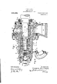
In the accompanying drawings which illustrate one of the embodiments of my invention, Figure 1 is an arial section of shaft and thrust bearings; Fig. 2 is a cross-sectional view of the same taken on line 2 2 of Fig. 1; Fig.i3 is a cross-sectional view taken on line 3-3 of Fig. 1;.and Fig. "4 is a perspective view 'showing the thrustcollars and spacers.
5 indicates the pillow block that is suit- Aably supported from a bed-plate or other means. This pillow block is provided with e a spherical surfacedse'at 6. Itis also proi vided with a removable head 7 that has a.
A30` `ing in the side of the pillow block and centers the head. The internal face of the'head Ishoulder 8 which fits into an annular openis provided with a spherical surface 9 that is struck fromthe same center as the surface 6. The head 7 is secured in place by a number of stud bolts and may be made in 'one piece or split as desired. The pillo-w block may be provided with a removable cap vor may be made solid as desired.
fLocated within the pillow block is a. tubular member 10 having an enlargement 11 which is provided with a spherical surface, this surface being struck from the same center as the spherical Vsurfaced seat. The diameter of the enlargement of the member 10 is somewhat less than the openin in the pillow block that receives the shoulder 8 on the head. By reason of this construction it is possible to remove' the tubular member vand the parts off the thrust bearing from one end vof vthe'shaft without affectingtlheV apparatus driven by the shaft other than to b'lo'ck'rup the shaft sufficiently `to support'the weight -ofthe parts.
yhLocatedwithai/nuttige enlargedhead of the Specification of Letters Patent. i
{runner-BEARING'.
Patented Jan. 3, A1911.
Application filed March 25, 1909. Serial No. 485,783.
'trbular member is a concentric sleeve 12 that is provided with a babbitt lining 13, the latter forming the bearing surface for supporting the shaft 14. The sleeve 12 is slipped into place in the tubular member from the right-.hand side and is held against axial movement by the shoulder 15 and the bolt 1,6, the latter bein carried by the tubular member and provi ed with an extension that enters a hole in the sleeve. The sleeve and lining are cut away at a central point to receive the oil ring 17, the latter extending into the well 18. The pillow block is provided with a chamber 19 that may or may not be filled with oil as desired. Oil may be supplied tothe bearing under pressure by the passage 20 formed in the pillow block and the Yp`assages'21 and 22 formed in the tubular member and' the bearing sleeve. To prevent the lubricant from working out of the bearing 'an annular chamber 23 is provided within which is located an oil thrower 24, the latter being carried by a shoulder on the shaft. The chamber 23 is or may be connected by one or more passages with the chamber 19 in the base of the pillow block, as indicated by the dotted line. As an additional precaution against the escape of lubricant, a batller 25 is provided that consists of an annular member having a series of internal grooves. The baffler. is provided with an outwardly-extending flange and the latter is bolted to the side face ofthe pillow block. As a further precaution a shield-plate 26 may be employed. Lubricant may be introduced intoy the bearing through the opening 27, and the passage 20 used as a drain.
The left hand portion of the tubular member is bored to receive the concentric sleeve 28. This sleeve is prevented from rotating by the spline 29 but may be'adjusted longitudinally. The right hand end of the sleeve is provided with an internal flange or shoulder 30 that acts as a fixed abutment or stop forthe stationary thrust collars 31 held against rotation by the spline 31,of which collars as many may be provided as it is desired. Between the stationary thrust collars are stationary s acers 32 made in the form of rings. The le t hand end of the sleeve is threaded internally to receive the nut 33, the latter serving to clamp the stationary thrust collars and the spacers securely in place against the shoulder 30.
shape and size except those .at the extreme ends which may have a thickness equal to the" against which thethrust collars'and spacers A are clamped. Splined on the shaft and rotating with it are thrust collars 35. These collars are separated one from the other by spacers 36. These spacers are 1dent1cal 1n diameter of the rollers or balls 37 that transmit the thrust from the rotar tionary thrust collars. The ro lers are held in -suitable containers 38.
The rotating thrust collars andspacers are held in place by a nut 39 that is mounted on the end of the shaft. By screwing the nut into place the parts are clamped between it and the shoulder `34.
In the particular illustration of my invention I have shown a multiple arrangement of cells or chambers formed of hardened steel arts or thrust collars, between which are ocated the hardened steel rollers.
articular, embodiment of my invention I llave shown four such cells or'units, each unit having two sets of rollers, one set to absorb the thrustin one direction andl theother 'to absorb the thrust in the opposite direction.'
All of the stationary thrust collars are of l the same thickness .so that they can be ground at one setting o n a grinding ma chine, thereby insuring exact uniformity. Similarly, the fixed and revolvlng spaces are all of thesame thickness so that they can be yground at one setting. This construction insures absolute uniformity as to dimensions of as many cells'or units `as it ma y be desir-l able' to use. The thrust load 1s divided equally between theseveral cells or units, ex-
mum, but even if this error is not' entirely ing rollers or eliminated, it is evident that in starting up the ap aratus whichever rollers are over size will a so'rb the complete thrust until they are worn l sufliciently to 'permit the remainyballs to` carry their proportionate share; a
Inla structure of this character it is highl desirable to be `able to adjust the longitudinal position of the shaft in order to ixthe clearances between the moving'parts eitherl on the turbine or on-the apparatus driven Ainsure freedom of operation, The clamping to the sta- In they `other means.
In a construction of this character it is highly desirable to keep the parts well lubricated. To this end I bore a hole 50l in the shaft and drill into it radial holes 51 which .the shaft rotates, the centrifugal force sucks l oil into the shaft and throws it outwardlyy I through -the radial pasages 51. Lubricant may be admitted to the chamber around the adjusting screw by the pipe 55, Fig. 2.
It is tobe noted that the tubular member which carries the stationary part of vthe thrust bearing has the same center of movement as does the shaft bearing. This means that no matter how much the shaft may be deflected, due to inaccuracies in alinement, spring-ing of the shaft, or sudden" changes in load, that the thrust collars. will also be moved and that they will at all times b'e held with their working faces perpendicular to the axis ofthe shaft. It -is evident that whatever force causes the shaft to be deiected it will correspondingly change the position of its bearing and with it thejposition ofthe parts of the ,thrust bearing. v
In accordance with the provisions of the patent statutes, I have described the principle of operation of my invention, together with-the-apparatus which now consider' to represent the best embodiment thereof;
but I desire'ftov have it understood that the ,apparatus shown' is only illustrative, and
that the invention can be carried out What I claim as new and desireto securev by Letters Patent of the United States, .is
1. In combination, a support having a spherical surfaced seat, a self-alining member carried thereby `and comprising an cu.
lot
extension that projects o beyond the support, a
largement movable on the and a tubular si e o t e support, a shaft, a arallel bearing for the shaft located in said enlargement, and
thrust collars carried by the tubular eXtension and also by the shaft which areat all times maintained perpendicular to the shaft axis.
2. In combination, a pillow block having a spherical surfaced seat, a self-'alining member carried thereby and comprising an enlargement movable on the seat and a tubular extension that projects outside yof and the shaft carried bythe enlargement and adjustable withit, said bearing extending substantially the entire a-Xial length of the enlargement, thrust means carried by the shaft, other thrust means carried by the tubular extension and cooperating with those on the shaft, and means for adjusting the shaft and the thrust means longitudinally.
3. In combinatioxn a pillow block having a spherical surfaced seat, a self alining member carried thereby and movable on the seat, a bearing for the shaft carried by said member and adjustable with it, a plurality of thrust collars mou ted on the shaft, 'a plurality 'of thrust co lars carried by said member, clamping means for said collars,
- rolling means located between said collars for transmitting thrust, and an adjusting screw for moving the shaft and the thrust collars longitudinally.
4. In combination, Ya support having a spherical surfaced seat, a selfalining member carried thereby and comprising an enlargement movable on the seat and a tubular portion eXtending'out-side of the support,
a shaftfmeansfor longitudinally adjusting the shaft within the tubular portion of the member, thrust .collars supported by said tubular portion, and other thrust collars supported by and turning with the shaft, which transmit the thrust thereof to said member.
5. In combination, a support having a spherical surfacedfseat, a sel alining member carried thereby and movable on the seat, a shaft, thrust collars supported by the member, other thrust collars supported by and turning with the shaft, spacers located between the stationary and also between the rotary thrust collars, and rolling means located between the collars for transmitting the thrust of the shaft to said member.
6. In combination, a support having a spherical surfaced seat; a self alining meml ber carried thereby and movable on the seat,
` thrust collars mounted on the shaft. a means for clamping the collars carried by the sleeve against axial movement, other means for clamping the collars carried by the shaft parallel' bearing for.
against axial movement, and rolling means located between the collarsfor transmitting thrust vfrom the shaft to said member. '7. In combination, a support having a spherical surfaced seata self alining member carried thereby and movable on the seat, a shaft, a sleeve located within said member and supportedthereby, thrust collarsm'ounted in the sleeve, other thrust collars mounted on the shaft, a means for clamping the collars carried by-the sleeve, other means for clamping the collars carried by the shaft, and a means carried by the tubular member fori adjusting the position of the sleeve.
.8. In combination, aA sup ort having a spherical surfaced seat a sel alining member carried thereby an movable on the seat,
a sleeve located within said member and supported thereby, thrust collars mounted in thesleeve, other thrust collars mounted vonl the shaft, a nut screw-threaded to the sleeve for clamping the stationary thrust collars, `a Y nut andvshoulder on the shaft for clamping the rotary thrust collars, rolling means located between the stationary and rotary eollars for transmitting the thrust of the shaft to said member, and an adjusting screw for s I adjusting the position of the sleeve in said member. i
9. In combination, a support having'a spherical surfaced seat, a self-alining tubularmember carriedthereby and movable on j the seat, a shaft, a sleeve splined inthe memf ber, stationary thrust collars carried by the sleeve, other collars carried by the shaft, spacers between both sets of collars, a clamp for securing the stationary collars and spacers, a clamp for securing the rotary collars and spacers on the shaft, rolling means Ylocated between the collars, and an adjusting screw that is anchored in the tubular member and engages a part of the clamp for moving the sleeve bodily to and fro.
10. In combination, a support having a spherical surfaced seat, a self-alining tubular' member carried thereby and movable onthe seat, a shaft, a sleeve s lined in the mem? ber, stationary thrust co lars carried by the sleeve, other collars carried by the shaft, spacers between both sets of collars, a cla-m for securing the stationary collars and spacers, a clamp for securin the rotary collars and spacers on thesha t, rolling means located between the collars, a divided head for one end of the tubular member, and an adjustingscrew that has a collar located bctween and confined by the parts of the head., one end of said screw being threaded into the clamp.
11. In combination, a' support having a spherical surfaced seat, a detachable YVhead therefor that is attached to the side of the support and forms a part of the seat and has a centering shoulder that is larger in dia1neter than the spherical surfaced. portion of 10l the' support, a series of thrust absorbing collars which may also be removed from one lthe `tubular member, a tubular member hav- ,if ing a spherical surfaced portion that en-` gages the seat and is held solely by it against Vaxlal movement and thrust collars carried 5 by the shaft and said member respectively. -1
1-2`. In combination, a support havin a spherical surfaced seat, a shaft, a self a inl ing member carried'thereby` 'which may be removed from the shaft by an endwise movement, a means for securing the member in' 20 member having an enlargement that engages -theseat, a parallel'bearin for the shaft carried by the member, a tu ular extension on said member, fixed collars carried by the shaft, xed collars carried by the tubular extension at one side A spline saone@ of said bearing, and' rollingv means located between the collars to transmit end thrust of the shaft in either direction to' the collars carried .by said member.
14. `In combination, a support having a seat, a member supported thereby and held l against axial movement,r said member includin a tubular extension, a sleevethat is g in the extension and is rovided at one end with an internal shoullder and at the'other end withl a screw thread,`collars mounted on the shaft and clamped against endvvise movement thereon, collars mounted in the sleeve, one of which engages the shoulder, ahead threaded to the sleeve for holding the collars carried thereby, and rollers between'the collars. 4
In witness whereof,l I have hereunto set my hand this 23rd day of March, 1909.
' FREDERIC R. CWBOYD. Witnesses:
DUGALD MaK, MoKILLoP, A CHARLES A. BARNARD.
Priority Applications (1)
| Application Number | Priority Date | Filing Date | Title |
|---|---|---|---|
| US48578309A US980482A (en) | 1909-03-25 | 1909-03-25 | Thrust-bearing. |
Applications Claiming Priority (1)
| Application Number | Priority Date | Filing Date | Title |
|---|---|---|---|
| US48578309A US980482A (en) | 1909-03-25 | 1909-03-25 | Thrust-bearing. |
Publications (1)
| Publication Number | Publication Date |
|---|---|
| US980482A true US980482A (en) | 1911-01-03 |
Family
ID=3048854
Family Applications (1)
| Application Number | Title | Priority Date | Filing Date |
|---|---|---|---|
| US48578309A Expired - Lifetime US980482A (en) | 1909-03-25 | 1909-03-25 | Thrust-bearing. |
Country Status (1)
| Country | Link |
|---|---|
| US (1) | US980482A (en) |
-
1909
- 1909-03-25 US US48578309A patent/US980482A/en not_active Expired - Lifetime
Similar Documents
| Publication | Publication Date | Title |
|---|---|---|
| US1364675A (en) | Mounting of spindles of grinding-machines, machine-tools, and other machinery | |
| US3754720A (en) | Expandible mandrel assembly | |
| US2514759A (en) | Drill chip breaker | |
| US980482A (en) | Thrust-bearing. | |
| SE7415741L (en) | ||
| US1298560A (en) | Means for transmitting rotary motion. | |
| US1251449A (en) | Clamping device for ball-bearings. | |
| US2258267A (en) | High speed thrust bearing | |
| US2947580A (en) | Bearing | |
| US2550908A (en) | High-speed rotor mounting | |
| US2390651A (en) | Rotary burnishing tool | |
| US1748247A (en) | Inking roller | |
| US2486227A (en) | High-speed grinding spindle | |
| US2555419A (en) | Live center chuck | |
| US2809475A (en) | Rotary tool holding device | |
| US602589A (en) | Thrust-bearing | |
| US2429516A (en) | Pilot bearing | |
| US1363466A (en) | Crank-shaft construction | |
| US2036977A (en) | Universal joint | |
| GB699099A (en) | Spindle support and bearings for machine tools | |
| US1280621A (en) | Antifriction-bearing. | |
| US1550834A (en) | Compensating bearing | |
| US1337028A (en) | Thrust-bearing | |
| US599040A (en) | Thrust-bearing for shafts | |
| US1202169A (en) | Expansion-reamer. |