US9803501B2 - Engine mid-turbine frame distributive coolant flow - Google Patents
Engine mid-turbine frame distributive coolant flow Download PDFInfo
- Publication number
- US9803501B2 US9803501B2 US14/607,102 US201514607102A US9803501B2 US 9803501 B2 US9803501 B2 US 9803501B2 US 201514607102 A US201514607102 A US 201514607102A US 9803501 B2 US9803501 B2 US 9803501B2
- Authority
- US
- United States
- Prior art keywords
- turbine
- outer cavity
- recited
- wall
- openings
- Prior art date
- Legal status (The legal status is an assumption and is not a legal conclusion. Google has not performed a legal analysis and makes no representation as to the accuracy of the status listed.)
- Active, expires
Links
Images


Classifications
-
- F—MECHANICAL ENGINEERING; LIGHTING; HEATING; WEAPONS; BLASTING
- F01—MACHINES OR ENGINES IN GENERAL; ENGINE PLANTS IN GENERAL; STEAM ENGINES
- F01D—NON-POSITIVE DISPLACEMENT MACHINES OR ENGINES, e.g. STEAM TURBINES
- F01D25/00—Component parts, details, or accessories, not provided for in, or of interest apart from, other groups
- F01D25/08—Cooling; Heating; Heat-insulation
- F01D25/14—Casings modified therefor
-
- F—MECHANICAL ENGINEERING; LIGHTING; HEATING; WEAPONS; BLASTING
- F01—MACHINES OR ENGINES IN GENERAL; ENGINE PLANTS IN GENERAL; STEAM ENGINES
- F01D—NON-POSITIVE DISPLACEMENT MACHINES OR ENGINES, e.g. STEAM TURBINES
- F01D25/00—Component parts, details, or accessories, not provided for in, or of interest apart from, other groups
- F01D25/08—Cooling; Heating; Heat-insulation
- F01D25/12—Cooling
-
- F—MECHANICAL ENGINEERING; LIGHTING; HEATING; WEAPONS; BLASTING
- F01—MACHINES OR ENGINES IN GENERAL; ENGINE PLANTS IN GENERAL; STEAM ENGINES
- F01D—NON-POSITIVE DISPLACEMENT MACHINES OR ENGINES, e.g. STEAM TURBINES
- F01D25/00—Component parts, details, or accessories, not provided for in, or of interest apart from, other groups
- F01D25/16—Arrangement of bearings; Supporting or mounting bearings in casings
- F01D25/162—Bearing supports
-
- F—MECHANICAL ENGINEERING; LIGHTING; HEATING; WEAPONS; BLASTING
- F01—MACHINES OR ENGINES IN GENERAL; ENGINE PLANTS IN GENERAL; STEAM ENGINES
- F01D—NON-POSITIVE DISPLACEMENT MACHINES OR ENGINES, e.g. STEAM TURBINES
- F01D9/00—Stators
- F01D9/02—Nozzles; Nozzle boxes; Stator blades; Guide conduits, e.g. individual nozzles
- F01D9/04—Nozzles; Nozzle boxes; Stator blades; Guide conduits, e.g. individual nozzles forming ring or sector
- F01D9/041—Nozzles; Nozzle boxes; Stator blades; Guide conduits, e.g. individual nozzles forming ring or sector using blades
-
- F—MECHANICAL ENGINEERING; LIGHTING; HEATING; WEAPONS; BLASTING
- F02—COMBUSTION ENGINES; HOT-GAS OR COMBUSTION-PRODUCT ENGINE PLANTS
- F02C—GAS-TURBINE PLANTS; AIR INTAKES FOR JET-PROPULSION PLANTS; CONTROLLING FUEL SUPPLY IN AIR-BREATHING JET-PROPULSION PLANTS
- F02C7/00—Features, components parts, details or accessories, not provided for in, or of interest apart form groups F02C1/00 - F02C6/00; Air intakes for jet-propulsion plants
- F02C7/12—Cooling of plants
- F02C7/16—Cooling of plants characterised by cooling medium
- F02C7/18—Cooling of plants characterised by cooling medium the medium being gaseous, e.g. air
-
- F—MECHANICAL ENGINEERING; LIGHTING; HEATING; WEAPONS; BLASTING
- F05—INDEXING SCHEMES RELATING TO ENGINES OR PUMPS IN VARIOUS SUBCLASSES OF CLASSES F01-F04
- F05D—INDEXING SCHEME FOR ASPECTS RELATING TO NON-POSITIVE-DISPLACEMENT MACHINES OR ENGINES, GAS-TURBINES OR JET-PROPULSION PLANTS
- F05D2220/00—Application
- F05D2220/30—Application in turbines
- F05D2220/32—Application in turbines in gas turbines
- F05D2220/321—Application in turbines in gas turbines for a special turbine stage
- F05D2220/3213—Application in turbines in gas turbines for a special turbine stage an intermediate stage of the turbine
-
- F—MECHANICAL ENGINEERING; LIGHTING; HEATING; WEAPONS; BLASTING
- F05—INDEXING SCHEMES RELATING TO ENGINES OR PUMPS IN VARIOUS SUBCLASSES OF CLASSES F01-F04
- F05D—INDEXING SCHEME FOR ASPECTS RELATING TO NON-POSITIVE-DISPLACEMENT MACHINES OR ENGINES, GAS-TURBINES OR JET-PROPULSION PLANTS
- F05D2240/00—Components
- F05D2240/10—Stators
- F05D2240/12—Fluid guiding means, e.g. vanes
- F05D2240/126—Baffles or ribs
-
- F—MECHANICAL ENGINEERING; LIGHTING; HEATING; WEAPONS; BLASTING
- F05—INDEXING SCHEMES RELATING TO ENGINES OR PUMPS IN VARIOUS SUBCLASSES OF CLASSES F01-F04
- F05D—INDEXING SCHEME FOR ASPECTS RELATING TO NON-POSITIVE-DISPLACEMENT MACHINES OR ENGINES, GAS-TURBINES OR JET-PROPULSION PLANTS
- F05D2240/00—Components
- F05D2240/10—Stators
- F05D2240/12—Fluid guiding means, e.g. vanes
- F05D2240/128—Nozzles
-
- F—MECHANICAL ENGINEERING; LIGHTING; HEATING; WEAPONS; BLASTING
- F05—INDEXING SCHEMES RELATING TO ENGINES OR PUMPS IN VARIOUS SUBCLASSES OF CLASSES F01-F04
- F05D—INDEXING SCHEME FOR ASPECTS RELATING TO NON-POSITIVE-DISPLACEMENT MACHINES OR ENGINES, GAS-TURBINES OR JET-PROPULSION PLANTS
- F05D2240/00—Components
- F05D2240/10—Stators
- F05D2240/14—Casings or housings protecting or supporting assemblies within
-
- F—MECHANICAL ENGINEERING; LIGHTING; HEATING; WEAPONS; BLASTING
- F05—INDEXING SCHEMES RELATING TO ENGINES OR PUMPS IN VARIOUS SUBCLASSES OF CLASSES F01-F04
- F05D—INDEXING SCHEME FOR ASPECTS RELATING TO NON-POSITIVE-DISPLACEMENT MACHINES OR ENGINES, GAS-TURBINES OR JET-PROPULSION PLANTS
- F05D2250/00—Geometry
- F05D2250/30—Arrangement of components
- F05D2250/31—Arrangement of components according to the direction of their main axis or their axis of rotation
- F05D2250/313—Arrangement of components according to the direction of their main axis or their axis of rotation the axes being perpendicular to each other
-
- F—MECHANICAL ENGINEERING; LIGHTING; HEATING; WEAPONS; BLASTING
- F05—INDEXING SCHEMES RELATING TO ENGINES OR PUMPS IN VARIOUS SUBCLASSES OF CLASSES F01-F04
- F05D—INDEXING SCHEME FOR ASPECTS RELATING TO NON-POSITIVE-DISPLACEMENT MACHINES OR ENGINES, GAS-TURBINES OR JET-PROPULSION PLANTS
- F05D2260/00—Function
- F05D2260/20—Heat transfer, e.g. cooling
- F05D2260/201—Heat transfer, e.g. cooling by impingement of a fluid
-
- Y—GENERAL TAGGING OF NEW TECHNOLOGICAL DEVELOPMENTS; GENERAL TAGGING OF CROSS-SECTIONAL TECHNOLOGIES SPANNING OVER SEVERAL SECTIONS OF THE IPC; TECHNICAL SUBJECTS COVERED BY FORMER USPC CROSS-REFERENCE ART COLLECTIONS [XRACs] AND DIGESTS
- Y02—TECHNOLOGIES OR APPLICATIONS FOR MITIGATION OR ADAPTATION AGAINST CLIMATE CHANGE
- Y02T—CLIMATE CHANGE MITIGATION TECHNOLOGIES RELATED TO TRANSPORTATION
- Y02T50/00—Aeronautics or air transport
- Y02T50/60—Efficient propulsion technologies, e.g. for aircraft
-
- Y02T50/676—
Definitions
- a mid-turbine frame is sometimes provided between the high pressure turbine and the low pressure turbine to aid in supporting bearing assemblies.
- the low pressure turbine case requires cooling air to maintain temperatures within a desired limit. Cooling air is extracted from the compressor section and routed to a cavity within the mid-turbine frame. Cooling air from the cavity within the mid-turbine frame is then routed to cool the low pressure turbine case. In some applications, the mid-turbine frame is at a temperature such that cooling air within the cavity is heated above a temperature capable of sufficiently cooling the low pressure turbine case.
- the baffle includes a plurality of openings for directing cooling air transverse to the radially inner wall of the outer cavity.
- the baffle is disposed within the outer cavity.
- the turbine section includes a high pressure turbine and a low pressure turbine and the frame is a mid-turbine frame which defines a flow path between the high pressure turbine and the low pressure turbine.
- the plurality of openings direct cooling airflow forward, aft and circumferentially within the outer cavity.
- the plurality of openings define an total opening area for metering cooling airflow into the outer cavity.
- FIG. 3 is a sectional view of a portion of the example mid-turbine frame assembly.
- FIG. 5 is a schematic view of the outer cavity and example baffle.
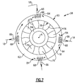
- FIG. 7 is a sectional view of cooling airflow within the example mid-turbine frame assembly.
- the example engine 20 generally includes a low speed spool 30 and a high speed spool 32 mounted for rotation about an engine central longitudinal axis A relative to an engine static structure 36 via several bearing systems 38 . It should be understood that various bearing systems 38 at various locations may alternatively or additionally be provided.
- a combustor 56 is arranged between the high pressure compressor 52 and the high pressure turbine 54 .
- the high pressure turbine 54 includes at least two stages to provide a double stage high pressure turbine 54 .
- the high pressure turbine 54 includes only a single stage.
- a “high pressure” compressor or turbine experiences a higher pressure than a corresponding “low pressure” compressor or turbine.
- Airflow through the core airflow path C is compressed by the low pressure compressor 44 then by the high pressure compressor 52 mixed with fuel and ignited in the combustor 56 to produce high speed exhaust gases that are then expanded through the high pressure turbine 54 and low pressure turbine 46 .
- the disclosed gas turbine engine 20 in one example is a high-bypass geared aircraft engine.
- the gas turbine engine 20 includes a bypass ratio greater than about six (6), with an example embodiment being greater than about ten (10).
- the example geared architecture 48 is an epicyclical gear train, such as a planetary gear system, star gear system or other known gear system, with a gear reduction ratio of greater than about 2.3.
- Low corrected fan tip speed is the actual fan tip speed in ft/sec divided by an industry standard temperature correction of [(Tram° R)/(518.7° R)] 0.5 .
- the “Low corrected fan tip speed”, as disclosed herein according to one non-limiting embodiment, is less than about 1150 ft/second (350 meters/second).
- an example mid-turbine frame assembly 58 includes an outer cavity 62 and an inner cavity 64 .
- the outer cavity 62 is disposed radially outward of the airfoils 60 and the inner cavity 64 is disposed radially inward of the airfoils 60 .
- Several LTCA supply pipes 66 deliver cooling air from the compressor section 24 to the outer cavity 62 .
- four (4) supply tubes 66 are arranged ninety (90) degrees apart about the circumference of the mid-turbine vane assembly 58 .
- different numbers of supply tubes 66 could be utilized in different locations about the mid-turbine vane assembly 58 .
- cooling air 18 is extracted from an initial stage of the high pressure compressor 52 .
- cooling air may be obtained from other portions of the engine 20 that include air at appropriate pressures and temperatures.
- Cooling air 18 is communicated to the outer cavity 62 to cool the mid-turbine frame 58 .
- the cooling air 18 is also communicated through the outer cavity 62 to a low pressure turbine (LPT) cavity 86 defined within a turbine case 74 ( FIG. 3 ) through a plurality of supply holes 72 .
- Cooling air 18 may also be communicated to the LPT cavity 86 through a feather seal 72 defined at an aft portion of the outer cavity 62 .
- LPT low pressure turbine
- the mid-turbine frame assembly 58 is very hot and therefore the temperature of the cooling air 18 provided to cool the low pressure turbine case 74 may require additional cooling features to provide a flow of a desired temperature determined to provide the desired cooling of the low pressure turbine 46 .
- Cooling air 18 that directly impinges on the radially inner wall 78 is heated and can reach temperatures above desired threshold values for fooling the turbine case 74 . Additionally, direct impingement of cooling air onto the inner wall 78 can result in non-uniform temperatures of the inner wall 78 that can increase thermal stresses.
- the example mid-turbine frame 58 includes baffles 68 at each inlet for cooling airflow 18 ( FIG. 7 ) such that airflow is directed circumferentially about the axis A.
- inlets 66 are spaced evenly apart about the axis A and provide cooling air to a corresponding baffle 68 .
- the baffle 68 distributes the cooling airflow 84 transverse to incoming airflow 18 and to the inner radial wall 78 to prevent absorption of excessive heat in any one location.
- the distribution provided by the baffles 68 generate a more uniform temperature distribution in both the radial wall 78 and the cooling air 84 circulating though the outer cavity 62 .
Landscapes
- Engineering & Computer Science (AREA)
- Mechanical Engineering (AREA)
- General Engineering & Computer Science (AREA)
- Chemical & Material Sciences (AREA)
- Combustion & Propulsion (AREA)
- Turbine Rotor Nozzle Sealing (AREA)
Priority Applications (1)
| Application Number | Priority Date | Filing Date | Title |
|---|---|---|---|
| US14/607,102 US9803501B2 (en) | 2014-02-14 | 2015-01-28 | Engine mid-turbine frame distributive coolant flow |
Applications Claiming Priority (2)
| Application Number | Priority Date | Filing Date | Title |
|---|---|---|---|
| US201461939950P | 2014-02-14 | 2014-02-14 | |
| US14/607,102 US9803501B2 (en) | 2014-02-14 | 2015-01-28 | Engine mid-turbine frame distributive coolant flow |
Publications (2)
| Publication Number | Publication Date |
|---|---|
| US20160245114A1 US20160245114A1 (en) | 2016-08-25 |
| US9803501B2 true US9803501B2 (en) | 2017-10-31 |
Family
ID=52633055
Family Applications (1)
| Application Number | Title | Priority Date | Filing Date |
|---|---|---|---|
| US14/607,102 Active 2036-01-31 US9803501B2 (en) | 2014-02-14 | 2015-01-28 | Engine mid-turbine frame distributive coolant flow |
Country Status (2)
| Country | Link |
|---|---|
| US (1) | US9803501B2 (fr) |
| EP (1) | EP2907978B1 (fr) |
Cited By (7)
| Publication number | Priority date | Publication date | Assignee | Title |
|---|---|---|---|---|
| US20180355747A1 (en) * | 2017-06-13 | 2018-12-13 | Rolls-Royce Corporation | Tip clearance control with variable speed blower |
| US20210079813A1 (en) * | 2014-11-25 | 2021-03-18 | Raytheon Technologies Corporation | Forged cast forged outer case for a gas turbine engine |
| US20220316352A1 (en) * | 2021-03-31 | 2022-10-06 | Raytheon Technologies Corporation | Flow diverter for mid-turbine frame cooling air delivery |
| US11466590B1 (en) * | 2021-06-17 | 2022-10-11 | Pratt & Whitney Canada Corp. | Mid-turbine frame with intermediary plenum |
| US11473439B1 (en) | 2021-09-23 | 2022-10-18 | General Electric Company | Gas turbine engine with hollow rotor in fluid communication with a balance piston cavity |
| US11549396B2 (en) | 2019-11-12 | 2023-01-10 | Pratt & Whitney Canada Corp. | Mid-turbine frame for gas turbine engine |
| US11698005B2 (en) | 2020-02-07 | 2023-07-11 | Raytheon Technologies Corporation | Flow diverter for mid-turbine frame cooling air delivery |
Families Citing this family (8)
| Publication number | Priority date | Publication date | Assignee | Title |
|---|---|---|---|---|
| JP6324548B2 (ja) * | 2014-06-10 | 2018-05-16 | シーメンス エナジー インコーポレイテッド | 排気ディフューザ内にロータセンタリング冷却システムを備えるガスタービンエンジン |
| US10247035B2 (en) | 2015-07-24 | 2019-04-02 | Pratt & Whitney Canada Corp. | Spoke locking architecture |
| US10443449B2 (en) | 2015-07-24 | 2019-10-15 | Pratt & Whitney Canada Corp. | Spoke mounting arrangement |
| US10914193B2 (en) | 2015-07-24 | 2021-02-09 | Pratt & Whitney Canada Corp. | Multiple spoke cooling system and method |
| US10975721B2 (en) | 2016-01-12 | 2021-04-13 | Pratt & Whitney Canada Corp. | Cooled containment case using internal plenum |
| EP3342991B1 (fr) * | 2016-12-30 | 2020-10-14 | Ansaldo Energia IP UK Limited | Déflecteurs pour le refroidissement dans une turbine à gaz |
| US10619492B2 (en) * | 2017-12-11 | 2020-04-14 | United Technologies Corporation | Vane air inlet with fillet |
| CN114198153B (zh) * | 2020-09-17 | 2024-05-03 | 中国航发商用航空发动机有限责任公司 | 涡轮叶片冷却系统及航空发动机 |
Citations (17)
| Publication number | Priority date | Publication date | Assignee | Title |
|---|---|---|---|---|
| US4321007A (en) | 1979-12-21 | 1982-03-23 | United Technologies Corporation | Outer case cooling for a turbine intermediate case |
| US5160241A (en) * | 1991-09-09 | 1992-11-03 | General Electric Company | Multi-port air channeling assembly |
| US5165847A (en) * | 1991-05-20 | 1992-11-24 | General Electric Company | Tapered enlargement metering inlet channel for a shroud cooling assembly of gas turbine engines |
| US5292227A (en) | 1992-12-10 | 1994-03-08 | General Electric Company | Turbine frame |
| US5630703A (en) | 1995-12-15 | 1997-05-20 | General Electric Company | Rotor disk post cooling system |
| US20030161716A1 (en) * | 2002-02-25 | 2003-08-28 | Honeywell International, Inc. | Method of forming a thermally isolated gas turbine engine housing |
| EP1526251A1 (fr) | 2003-10-22 | 2005-04-27 | General Electric Company | Configuration de refroidissement pour une aube de turbine |
| US20080206042A1 (en) * | 2006-11-30 | 2008-08-28 | Ching-Pang Lee | Methods and system for recuperated circumferential cooling of integral turbine nozzle and shroud assemblies |
| US20090238678A1 (en) * | 2008-03-21 | 2009-09-24 | Nyamu Kinyua N | Cold air buffer supply tube |
| US20100303610A1 (en) * | 2009-05-29 | 2010-12-02 | United Technologies Corporation | Cooled gas turbine stator assembly |
| US20110079019A1 (en) | 2009-10-01 | 2011-04-07 | Pratt & Whitney Canada Corp. | Cooling air system for mid turbine frame |
| US8100633B2 (en) * | 2008-03-11 | 2012-01-24 | United Technologies Corp. | Cooling air manifold splash plates and gas turbines engine systems involving such splash plates |
| US8245518B2 (en) | 2008-11-28 | 2012-08-21 | Pratt & Whitney Canada Corp. | Mid turbine frame system for gas turbine engine |
| US8366382B1 (en) | 2012-01-31 | 2013-02-05 | United Technologies Corporation | Mid-turbine frame buffer system |
| EP2573329A2 (fr) | 2011-09-22 | 2013-03-27 | Pratt & Whitney Canada Corp. | Architecture de système d'air pour un module de cadre de turbine intermédiaire |
| US20130149107A1 (en) * | 2011-12-08 | 2013-06-13 | Mrinal Munshi | Gas turbine outer case active ambient cooling including air exhaust into a sub-ambient region of exhaust flow |
| WO2014175969A2 (fr) | 2013-03-13 | 2014-10-30 | United Technologies Corporation | Tube de transfert du cadre de turbine centrale d'un moteur pour refroidissement du carter de turbine à basse pression |
-
2015
- 2015-01-28 US US14/607,102 patent/US9803501B2/en active Active
- 2015-02-12 EP EP15154920.1A patent/EP2907978B1/fr active Active
Patent Citations (21)
| Publication number | Priority date | Publication date | Assignee | Title |
|---|---|---|---|---|
| US4321007A (en) | 1979-12-21 | 1982-03-23 | United Technologies Corporation | Outer case cooling for a turbine intermediate case |
| US5165847A (en) * | 1991-05-20 | 1992-11-24 | General Electric Company | Tapered enlargement metering inlet channel for a shroud cooling assembly of gas turbine engines |
| US5160241A (en) * | 1991-09-09 | 1992-11-03 | General Electric Company | Multi-port air channeling assembly |
| US5292227A (en) | 1992-12-10 | 1994-03-08 | General Electric Company | Turbine frame |
| US5630703A (en) | 1995-12-15 | 1997-05-20 | General Electric Company | Rotor disk post cooling system |
| US20030161716A1 (en) * | 2002-02-25 | 2003-08-28 | Honeywell International, Inc. | Method of forming a thermally isolated gas turbine engine housing |
| EP1526251A1 (fr) | 2003-10-22 | 2005-04-27 | General Electric Company | Configuration de refroidissement pour une aube de turbine |
| US6929445B2 (en) * | 2003-10-22 | 2005-08-16 | General Electric Company | Split flow turbine nozzle |
| US20080206042A1 (en) * | 2006-11-30 | 2008-08-28 | Ching-Pang Lee | Methods and system for recuperated circumferential cooling of integral turbine nozzle and shroud assemblies |
| US8100633B2 (en) * | 2008-03-11 | 2012-01-24 | United Technologies Corp. | Cooling air manifold splash plates and gas turbines engine systems involving such splash plates |
| US20090238678A1 (en) * | 2008-03-21 | 2009-09-24 | Nyamu Kinyua N | Cold air buffer supply tube |
| US8245518B2 (en) | 2008-11-28 | 2012-08-21 | Pratt & Whitney Canada Corp. | Mid turbine frame system for gas turbine engine |
| US20100303610A1 (en) * | 2009-05-29 | 2010-12-02 | United Technologies Corporation | Cooled gas turbine stator assembly |
| EP2264282A2 (fr) | 2009-05-29 | 2010-12-22 | United Technologies Corporation | Ensemble de stator de turbine à gaz refroidi |
| US20110079019A1 (en) | 2009-10-01 | 2011-04-07 | Pratt & Whitney Canada Corp. | Cooling air system for mid turbine frame |
| US8371127B2 (en) | 2009-10-01 | 2013-02-12 | Pratt & Whitney Canada Corp. | Cooling air system for mid turbine frame |
| EP2573329A2 (fr) | 2011-09-22 | 2013-03-27 | Pratt & Whitney Canada Corp. | Architecture de système d'air pour un module de cadre de turbine intermédiaire |
| US20130078080A1 (en) * | 2011-09-22 | 2013-03-28 | Eric Durocher | Air system architecture for a mid-turbine frame module |
| US20130149107A1 (en) * | 2011-12-08 | 2013-06-13 | Mrinal Munshi | Gas turbine outer case active ambient cooling including air exhaust into a sub-ambient region of exhaust flow |
| US8366382B1 (en) | 2012-01-31 | 2013-02-05 | United Technologies Corporation | Mid-turbine frame buffer system |
| WO2014175969A2 (fr) | 2013-03-13 | 2014-10-30 | United Technologies Corporation | Tube de transfert du cadre de turbine centrale d'un moteur pour refroidissement du carter de turbine à basse pression |
Non-Patent Citations (1)
| Title |
|---|
| Extended European Search Report for EP Application No. 15154920.1 dated Jun. 22, 2015. |
Cited By (11)
| Publication number | Priority date | Publication date | Assignee | Title |
|---|---|---|---|---|
| US20210079813A1 (en) * | 2014-11-25 | 2021-03-18 | Raytheon Technologies Corporation | Forged cast forged outer case for a gas turbine engine |
| US11649737B2 (en) * | 2014-11-25 | 2023-05-16 | Raytheon Technologies Corporation | Forged cast forged outer case for a gas turbine engine |
| US20180355747A1 (en) * | 2017-06-13 | 2018-12-13 | Rolls-Royce Corporation | Tip clearance control with variable speed blower |
| US10428676B2 (en) * | 2017-06-13 | 2019-10-01 | Rolls-Royce Corporation | Tip clearance control with variable speed blower |
| US20200165933A1 (en) * | 2017-06-13 | 2020-05-28 | Rolls-Royce Corporation | Tip clearance control system |
| US10920602B2 (en) * | 2017-06-13 | 2021-02-16 | Rolls-Royce Corporation | Tip clearance control system |
| US11549396B2 (en) | 2019-11-12 | 2023-01-10 | Pratt & Whitney Canada Corp. | Mid-turbine frame for gas turbine engine |
| US11698005B2 (en) | 2020-02-07 | 2023-07-11 | Raytheon Technologies Corporation | Flow diverter for mid-turbine frame cooling air delivery |
| US20220316352A1 (en) * | 2021-03-31 | 2022-10-06 | Raytheon Technologies Corporation | Flow diverter for mid-turbine frame cooling air delivery |
| US11466590B1 (en) * | 2021-06-17 | 2022-10-11 | Pratt & Whitney Canada Corp. | Mid-turbine frame with intermediary plenum |
| US11473439B1 (en) | 2021-09-23 | 2022-10-18 | General Electric Company | Gas turbine engine with hollow rotor in fluid communication with a balance piston cavity |
Also Published As
| Publication number | Publication date |
|---|---|
| US20160245114A1 (en) | 2016-08-25 |
| EP2907978B1 (fr) | 2017-11-22 |
| EP2907978A1 (fr) | 2015-08-19 |
Similar Documents
| Publication | Publication Date | Title |
|---|---|---|
| US9803501B2 (en) | Engine mid-turbine frame distributive coolant flow | |
| US10087782B2 (en) | Engine mid-turbine frame transfer tube for low pressure turbine case cooling | |
| EP2961942B1 (fr) | Procédé et appareil de gestion de flux d'air de prédiffusion destiné à refroidir des éléments d'une turbine à gaz | |
| US10253632B2 (en) | Compressor rim thermal management | |
| US9828914B2 (en) | Thermal management system and method of circulating air in a gas turbine engine | |
| US9982542B2 (en) | Airfoil platform impingement cooling holes | |
| EP3039264B1 (fr) | Agencement de refroidissement et de mélange de diffuseur de turbine à gaz | |
| US10815891B2 (en) | Inner diffuser case struts for a combustor of a gas turbine engine | |
| EP2900998B1 (fr) | Écoulement d'air formant tampon vers un compartiment de palier | |
| US10323524B2 (en) | Axial skin core cooling passage for a turbine engine component | |
| US10024172B2 (en) | Gas turbine engine airfoil | |
| US9856750B2 (en) | Cooling passages for a mid-turbine frame | |
| US20160305254A1 (en) | Rotor blade platform cooling passage | |
| US20180298770A1 (en) | Forward facing tangential onboard injectors for gas turbine engines | |
| US20160208644A1 (en) | Cooling passages for a mid-turbine frame | |
| US10648351B2 (en) | Gas turbine engine cooling component | |
| US20160312654A1 (en) | Turbine airfoil cooling | |
| US10494929B2 (en) | Cooled airfoil structure | |
| US11415020B2 (en) | Gas turbine engine flowpath component including vectored cooling flow holes | |
| US20190211686A1 (en) | Gas turbine engine airfoil with cooling path |
Legal Events
| Date | Code | Title | Description |
|---|---|---|---|
| STCF | Information on status: patent grant |
Free format text: PATENTED CASE |
|
| CC | Certificate of correction | ||
| AS | Assignment |
Owner name: RAYTHEON TECHNOLOGIES CORPORATION, MASSACHUSETTS Free format text: CHANGE OF NAME;ASSIGNOR:UNITED TECHNOLOGIES CORPORATION;REEL/FRAME:054062/0001 Effective date: 20200403 |
|
| AS | Assignment |
Owner name: RAYTHEON TECHNOLOGIES CORPORATION, CONNECTICUT Free format text: CORRECTIVE ASSIGNMENT TO CORRECT THE AND REMOVE PATENT APPLICATION NUMBER 11886281 AND ADD PATENT APPLICATION NUMBER 14846874. TO CORRECT THE RECEIVING PARTY ADDRESS PREVIOUSLY RECORDED AT REEL: 054062 FRAME: 0001. ASSIGNOR(S) HEREBY CONFIRMS THE CHANGE OF ADDRESS;ASSIGNOR:UNITED TECHNOLOGIES CORPORATION;REEL/FRAME:055659/0001 Effective date: 20200403 |
|
| MAFP | Maintenance fee payment |
Free format text: PAYMENT OF MAINTENANCE FEE, 4TH YEAR, LARGE ENTITY (ORIGINAL EVENT CODE: M1551); ENTITY STATUS OF PATENT OWNER: LARGE ENTITY Year of fee payment: 4 |
|
| AS | Assignment |
Owner name: RTX CORPORATION, CONNECTICUT Free format text: CHANGE OF NAME;ASSIGNOR:RAYTHEON TECHNOLOGIES CORPORATION;REEL/FRAME:064714/0001 Effective date: 20230714 |