US9801308B2 - Managing cable connections and air flow in a data center - Google Patents
Managing cable connections and air flow in a data center Download PDFInfo
- Publication number
- US9801308B2 US9801308B2 US15/065,622 US201615065622A US9801308B2 US 9801308 B2 US9801308 B2 US 9801308B2 US 201615065622 A US201615065622 A US 201615065622A US 9801308 B2 US9801308 B2 US 9801308B2
- Authority
- US
- United States
- Prior art keywords
- housing
- opening
- air flow
- barrier
- network
- Prior art date
- Legal status (The legal status is an assumption and is not a legal conclusion. Google has not performed a legal analysis and makes no representation as to the accuracy of the status listed.)
- Active
Links
Images


Classifications
-
- H—ELECTRICITY
- H05—ELECTRIC TECHNIQUES NOT OTHERWISE PROVIDED FOR
- H05K—PRINTED CIRCUITS; CASINGS OR CONSTRUCTIONAL DETAILS OF ELECTRIC APPARATUS; MANUFACTURE OF ASSEMBLAGES OF ELECTRICAL COMPONENTS
- H05K7/00—Constructional details common to different types of electric apparatus
- H05K7/14—Mounting supporting structure in casing or on frame or rack
- H05K7/1485—Servers; Data center rooms, e.g. 19-inch computer racks
- H05K7/1488—Cabinets therefor, e.g. chassis or racks or mechanical interfaces between blades and support structures
- H05K7/1491—Cabinets therefor, e.g. chassis or racks or mechanical interfaces between blades and support structures having cable management arrangements
-
- H—ELECTRICITY
- H05—ELECTRIC TECHNIQUES NOT OTHERWISE PROVIDED FOR
- H05K—PRINTED CIRCUITS; CASINGS OR CONSTRUCTIONAL DETAILS OF ELECTRIC APPARATUS; MANUFACTURE OF ASSEMBLAGES OF ELECTRICAL COMPONENTS
- H05K7/00—Constructional details common to different types of electric apparatus
- H05K7/20—Modifications to facilitate cooling, ventilating, or heating
- H05K7/20709—Modifications to facilitate cooling, ventilating, or heating for server racks or cabinets; for data centers, e.g. 19-inch computer racks
-
- G—PHYSICS
- G06—COMPUTING OR CALCULATING; COUNTING
- G06F—ELECTRIC DIGITAL DATA PROCESSING
- G06F1/00—Details not covered by groups G06F3/00 - G06F13/00 and G06F21/00
- G06F1/16—Constructional details or arrangements
- G06F1/18—Packaging or power distribution
- G06F1/181—Enclosures
-
- H—ELECTRICITY
- H04—ELECTRIC COMMUNICATION TECHNIQUE
- H04Q—SELECTING
- H04Q1/00—Details of selecting apparatus or arrangements
- H04Q1/02—Constructional details
-
- H—ELECTRICITY
- H04—ELECTRIC COMMUNICATION TECHNIQUE
- H04Q—SELECTING
- H04Q1/00—Details of selecting apparatus or arrangements
- H04Q1/02—Constructional details
- H04Q1/035—Cooling of active equipments, e.g. air ducts
-
- H—ELECTRICITY
- H04—ELECTRIC COMMUNICATION TECHNIQUE
- H04Q—SELECTING
- H04Q1/00—Details of selecting apparatus or arrangements
- H04Q1/02—Constructional details
- H04Q1/13—Patch panels for monitoring, interconnecting or testing circuits, e.g. patch bay, patch field or jack field; Patching modules
-
- F—MECHANICAL ENGINEERING; LIGHTING; HEATING; WEAPONS; BLASTING
- F28—HEAT EXCHANGE IN GENERAL
- F28F—DETAILS OF HEAT-EXCHANGE AND HEAT-TRANSFER APPARATUS, OF GENERAL APPLICATION
- F28F13/00—Arrangements for modifying heat-transfer, e.g. increasing, decreasing
- F28F13/16—Arrangements for modifying heat-transfer, e.g. increasing, decreasing by applying an electrostatic field to the body of the heat-exchange medium
-
- H—ELECTRICITY
- H02—GENERATION; CONVERSION OR DISTRIBUTION OF ELECTRIC POWER
- H02B—BOARDS, SUBSTATIONS OR SWITCHING ARRANGEMENTS FOR THE SUPPLY OR DISTRIBUTION OF ELECTRIC POWER
- H02B1/00—Frameworks, boards, panels, desks, casings; Details of substations or switching arrangements
- H02B1/015—Boards, panels, desks; Parts thereof or accessories therefor
- H02B1/06—Boards, panels, desks; Parts thereof or accessories therefor having associated enclosures, e.g. for preventing access to live parts
-
- H—ELECTRICITY
- H05—ELECTRIC TECHNIQUES NOT OTHERWISE PROVIDED FOR
- H05K—PRINTED CIRCUITS; CASINGS OR CONSTRUCTIONAL DETAILS OF ELECTRIC APPARATUS; MANUFACTURE OF ASSEMBLAGES OF ELECTRICAL COMPONENTS
- H05K5/00—Casings, cabinets or drawers for electric apparatus
-
- H—ELECTRICITY
- H05—ELECTRIC TECHNIQUES NOT OTHERWISE PROVIDED FOR
- H05K—PRINTED CIRCUITS; CASINGS OR CONSTRUCTIONAL DETAILS OF ELECTRIC APPARATUS; MANUFACTURE OF ASSEMBLAGES OF ELECTRICAL COMPONENTS
- H05K7/00—Constructional details common to different types of electric apparatus
Definitions
- the present invention relates to managing cable connections and air flow in a data center, and more particularly, to electronic devices having mechanisms for managing cable connections and air flow in a flexible manner.
- An information handling system generally processes, compiles, stores, and/or communicates information or data for business, personal, or other purposes thereby allowing users to take advantage of the value of the information.
- information handling systems may also vary regarding what information is handled, how the information is handled, how much information is processed, stored, or communicated, and how quickly and efficiently the information may be processed, stored, or communicated.
- the variations in information handling systems allow for information handling systems to be general or configured for a specific user or specific use such as financial transaction processing, airline reservations, enterprise data storage, or global communications.
- information handling systems may include a variety of hardware and software components that may be configured to process, store, and communicate information and may include one or more computer systems, data storage systems, and networking systems.
- FIG. 1 shows a schematic diagram 100 of conventional racks in an air-conditioned computer room. As depicted, two rows of racks, 104 and 106 are located on a floor 102 , where each rack (e.g., 106 a ) may accommodate multiple electronic devices (or, equivalently, equipment) (e.g., network switches 106 a 1 - 106 a 5 ).
- An air conditioning (AC) unit (not shown in FIG.
- the typical method of racking the equipment is to pull in cooler air from the aisle 150 and discharge warmer air to the adjacent aisle 152 (or 154 ), as indicated by the arrows 110 (or 111 ).
- FIG. 2 shows an enlarge view of the network switches 106 a 1 - 106 a 4 , where each of the switches has multiple ports 134 for receiving network cable plugs/jacks of the cables 140 - 146 .
- the network switches 106 a 1 - 106 a 4 have slots/holes 133 that are aligned to the holes 137 in the rack 106 a and receive suitable fasteners 135 , such as bolts, so that the network switches are installed in the rack 106 a .
- the direction of the ports 134 and cables 140 - 146 typically face both front and back of the rack. It is quite common for a single rack to have over a hundred cables coming out of one or both sides (the majority of them from network switches) of the rack 106 a , making cable management a substantial issue.
- the network technician or administrator install/arrange the racks in a direction that will allow for most efficient cooling, that is, to pull cold air from the cold aisle 150 and push the hot (used) air to the hot aisle ( 152 , 154 ) to be returned to the AC system for cooling.
- efficient airflow over cable management it often leaves dozens of cables coming out of both the front and back of the rack 106 a.
- the network engineer may decide whether he wants (1) efficient cabling (not running cables from front to back of the rack, over the top of the rack, around corners, or through the rack, which wastes valuable racking spaces and costs more for cooling) or (2) efficient air flow (not cycling warm air through many systems, causing high AC cost and higher likelihood of thermal issues on the equipment.)
- the interstitial space between two neighboring network switches is not large enough to accommodate the network cables therein.
- the engineer may leave openings between the network switches (i.e., increase the interstitial space between the network switches) and passes cables 140 - 146 through the openings.
- this approach wastes rack space and creates insufficient air flow between front and back of the rack 106 a (i.e., the cold aisle 150 and the hot aisle ( 152 , 154 ). As such, there is a need for an approach for efficient cabling without compromising air flow efficiency.
- FIG. 1 shows a conventional arrangement of racks in an air-conditioned computer room.
- FIG. 2 shows conventional network switches that each have multiple ports for network cables.
- FIG. 3 shows network switches according to embodiments of the present disclosure.
- FIG. 4A shows a perspective view of a network switch in FIG. 3 .
- FIG. 4B shows a cross sectional view of the network switch in FIG. 4A , taken along the direction 4 B- 4 B.
- FIG. 5 shows a cross sectional view of a network switch in FIG. 3 , where a network cable is connected to the network switch according to embodiments of the present disclosure.
- FIG. 6 shows a network switch according to embodiments of the present disclosure.
- FIG. 7 shows a cross sectional view of the network switch in FIG. 6 , taken along the direction 7 - 7 .
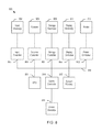
- FIG. 8 shows a computer system according to embodiments of the present disclosure.
- connections between components or systems within the figures are not intended to be limited to direct connections. Rather, data between these components may be modified, re-formatted, or otherwise changed by intermediary components. Also, additional or fewer connections may be used. It shall also be noted that the terms “coupled” “connected” or “communicatively coupled” shall be understood to include direct connections, indirect connections through one or more intermediary devices, and wireless connections.
- a service, function, or resource is not limited to a single service, function, or resource; usage of these terms may refer to a grouping of related services, functions, or resources, which may be distributed or aggregated.
- FIG. 3 shows network switches 202 a - 202 d according to embodiments of the present disclosure.
- the network switches 202 a - 202 d may be installed in a rack (e.g., 106 a ) by use of the holes 216 on their front panels.
- the holes 216 may be formed in a rack mounting portion 215 of the housing of each network switch.
- Each switch manages the flow of data across a network by transmitting a received message to the one or more devices for which the message was intended.
- FIG. 3 shows only network switches 202 a - 202 d mounted on a rack.
- each of the network switches 202 a - 202 d may be replaced by any other suitable type of information handling system that can be mounted on the rack.
- each of the network switches 202 a - 202 d may have multiple ports 204 for receiving plugs of network cables 240 to enable communication between different networked devices.
- Each of the network switches may have a control panel 206 that allows the network engineer to control the switch. It is noted that each of the network switches may have different heights, such as 1-rack unit (RU), 2-RU, or multiple RUs.
- each of the network switches 202 a - 202 d has one or more notches (or, openings or slots) through which the cables 240 can pass from front to rear or from rear to front of the switches without sacrificing the rack space.
- each of the switches 202 a and 202 b have a notch 270 in the top side
- the switch 202 c has a notch 272 in the bottom side.
- the switch 202 d has three notches 272 and 274 in the top and sides. It should be apparent to those of ordinary skill in the art that each of the switches may have one or more of the notches 270 - 274 and that the notches 270 - 274 may have various shapes, sizes and locations.
- FIG. 4A shows a perspective view of the network switch 202 a in FIG. 3 .
- FIG. 4B shows a cross sectional view of the network switch 202 a in FIG. 4A , taken along the direction 4 B- 4 B.
- the housing 254 may surround the space 250 in which various electronic components are located, where the electronic components are communicatively coupled to the ports 204 and perform the main function of the network switch 202 a , such as routing data from one port to another port.
- the housing 254 includes a plurality of surfaces that form an interior compartment for receiving and at least partially enclosing the electronic components of the network switch 202 a .
- the network switch 202 a may have one or more ports 205 on its rear side.
- the cable routing volumetric space 252 which is defined by the top surface of the housing 254 and the side wall 253 , provides a channel through which the cables can pass.
- the network switch 202 a may not have the side wall 253 that extends above the top surface of the housing.
- the interior compartment defined by the housing 254 and the cable routing volumetric space 252 define a combined dimensional space that is a standardized rack unit (RU) size when installed on a rack.
- RU rack unit
- FIG. 5 shows a cross sectional view of the network switch 202 b in FIG. 3 , where the plug of the network cable 240 is inserted into the port 204 according to embodiments of the present disclosure.
- the cable 240 may pass through the notch 210 and the interstitial space 252 .
- the notch 270 (or 272 and 274 ) allows the cable 240 to pass from front to rear of the network switch 202 b through the network device.
- the notch 270 (or 272 or 274 ) gives advantage of not having to have multiple Stock keeping Units/parts for front to back and back to front air flow by allowing the network switch to be reversed in the rack and cables to be connected through the rack without using up a space in the rack.
- the longer cables that are used in the conventional network switches 106 a 1 - 106 a 4 to go around the rack are very costly and can be hazardous when the cables 140 - 146 are in walking space on the floor, display a poor appearance and block the view of the switches.
- the notches 270 - 274 may relieve/eliminate these problems that the longer cables in the conventional systems may cause.
- network devices in FIGS. 4A-5 have ports 204 and 205 on both the front and back sides. However, it should be apparent to those of ordinary skill in the art that ports may be formed on only one of the front and back sides. It is also noted that network switch 202 c has a notch 272 formed on the bottom surface of the housing. In such a case, the interstitial space that is similar to the interstitial space 252 may be formed on the bottom side of the housing so that the network cable passes through the interstitial space and the notch 272 .
- the network switches 202 a - 202 d may be placed between a cold aisle (such as 150 ) and a hot aisle (such as 152 or 154 ), where the cold air pulled from the cold aisle may flow through the network switches to extract the heat energy generated by the network switches and the warm/heated air may be discharged to the hot aisle.
- one or more of the network switches 202 a - 202 d may have mechanisms, such as fans, to generate the air flow.
- the notches 270 - 274 themselves may be like open doors and allow any air to pass through.
- FIG. 6 shows a network switch 600 according to embodiments of the present disclosure.
- FIG. 7 shows a cross sectional view of the network switch 600 in FIG. 6 , taken along the direction 7 - 7 .
- the network switch 600 is similar to the network switch 202 b , with the difference that a barrier 602 may be placed in the open notch.
- the barrier 602 may ensure proper air flow continues between the front and back of the rack.
- the barrier 602 may include flexible fingers, brush type material, compressed foam, or any other suitable material.
- a blank panel may also be placed in the notch to ensure proper cooling air flow between the front and back of the rack.
- FIGS. 3-7 To illustrate the beneficial effects of the notches, only network switches are shown in FIGS. 3-7 .
- the devices that implement at least one or more of the functions and/or operations described herein may comprise an application or applications operating on at least one computing system.
- the computing system may comprise one or more computers and one or more databases.
- the computer system may be a single system, a distributed system, a cloud-based computer system, or a combination thereof.
- an information handling system may include any instrumentality or aggregate of instrumentalities operable to compute, calculate, determine, classify, process, transmit, receive, retrieve, originate, switch, store, display, communicate, manifest, detect, record, reproduce, handle, or utilize any form of information, intelligence, or data for business, scientific, control, or other purposes.
- an information handling system may be a personal computer (e.g., desktop or laptop), tablet computer, mobile device (e.g., personal digital assistant (PDA) or smart phone), server (e.g., blade server or rack server), a network storage device, or any other suitable device and may vary in size, shape, performance, functionality, and price.
- the information handling system may include random access memory (RAM), one or more processing resources such as a central processing unit (CPU) or hardware or software control logic, ROM, and/or other types of nonvolatile memory. Additional components of the information handling system may include one or more disk drives, one or more network ports for communicating with external devices as well as various input and output (I/O) devices, such as a keyboard, a mouse, touchscreen and/or a video display. The information handling system may also include one or more buses operable to transmit communications between the various hardware components.
- RAM random access memory
- processing resources such as a central processing unit (CPU) or hardware or software control logic
- ROM read-only memory
- Additional components of the information handling system may include one or more disk drives, one or more network ports for communicating with external devices as well as various input and output (I/O) devices, such as a keyboard, a mouse, touchscreen and/or a video display.
- I/O input and output
- the information handling system may also include one or more buses operable to transmit communications between the various
- system 800 which may include one or more notches, will now be described with reference to FIG. 8 , although differently configured information handling systems may also be employed.
- Each device/equipment in FIGS. 3-7 may include one or more components in the information handling system 800 .
- system 800 includes a central processing unit (CPU) 801 that provides computing resources and controls the computer.
- CPU 801 may be implemented with a microprocessor or the like, and may also include a graphics processor and/or a floating point coprocessor for mathematical computations.
- System 800 may also include a system memory 802 , which may be in the form of random-access memory (RAM) and read-only memory (ROM).
- RAM random-access memory
- ROM read-only memory
- An input controller 803 represents an interface to various input device(s) 804 , such as a keyboard, mouse, or stylus.
- a scanner controller 805 which communicates with a scanner 806 .
- System 800 may also include a storage controller 807 for interfacing with one or more storage devices 808 each of which includes a storage medium such as magnetic tape or disk, or an optical medium that might be used to record programs of instructions for operating systems, utilities and applications which may include embodiments of programs that implement various aspects of the present disclosure.
- Storage device(s) 808 may also be used to store processed data or data to be processed in accordance with the disclosure.
- System 800 may also include a display controller 809 for providing an interface to a display device 811 , which may be a cathode ray tube (CRT), a thin film transistor (TFT) display, or other type of display.
- System 800 may also include a printer controller 812 for communicating with a printer 813 .
- a communications controller 814 may interface with one or more communication devices 815 , which enables system 800 to connect to remote devices through any of a variety of networks including the Internet, an Ethernet cloud, an FCoE/DCB cloud, a local area network (LAN), a wide area network (WAN), a storage area network (SAN) or through any suitable electromagnetic carrier signals including infrared signals.
- LAN local area network
- WAN wide area network
- SAN storage area network
- bus 816 which may represent more than one physical bus.
- various system components may or may not be in physical proximity to one another.
- input data and/or output data may be remotely transmitted from one physical location to another.
- programs that implement various aspects of this disclosure may be accessed from a remote location (e.g., a server) over a network.
- Such data and/or programs may be conveyed through any of a variety of machine-readable medium including, but are not limited to: magnetic media such as hard disks, floppy disks, and magnetic tape; optical media such as CD-ROMs and holographic devices; magneto-optical media; and hardware devices that are specially configured to store or to store and execute program code, such as application specific integrated circuits (ASICs), programmable logic devices (PLDs), flash memory devices, and ROM and RAM devices.
- ASICs application specific integrated circuits
- PLDs programmable logic devices
- flash memory devices ROM and RAM devices.
Landscapes
- Engineering & Computer Science (AREA)
- Computer Hardware Design (AREA)
- General Engineering & Computer Science (AREA)
- Physics & Mathematics (AREA)
- Microelectronics & Electronic Packaging (AREA)
- Computer Networks & Wireless Communication (AREA)
- Theoretical Computer Science (AREA)
- Thermal Sciences (AREA)
- Power Engineering (AREA)
- Human Computer Interaction (AREA)
- General Physics & Mathematics (AREA)
- Cooling Or The Like Of Electrical Apparatus (AREA)
Abstract
Description
Claims (10)
Priority Applications (1)
| Application Number | Priority Date | Filing Date | Title |
|---|---|---|---|
| US15/065,622 US9801308B2 (en) | 2016-03-09 | 2016-03-09 | Managing cable connections and air flow in a data center |
Applications Claiming Priority (1)
| Application Number | Priority Date | Filing Date | Title |
|---|---|---|---|
| US15/065,622 US9801308B2 (en) | 2016-03-09 | 2016-03-09 | Managing cable connections and air flow in a data center |
Publications (2)
| Publication Number | Publication Date |
|---|---|
| US20170265333A1 US20170265333A1 (en) | 2017-09-14 |
| US9801308B2 true US9801308B2 (en) | 2017-10-24 |
Family
ID=59787465
Family Applications (1)
| Application Number | Title | Priority Date | Filing Date |
|---|---|---|---|
| US15/065,622 Active US9801308B2 (en) | 2016-03-09 | 2016-03-09 | Managing cable connections and air flow in a data center |
Country Status (1)
| Country | Link |
|---|---|
| US (1) | US9801308B2 (en) |
Cited By (3)
| Publication number | Priority date | Publication date | Assignee | Title |
|---|---|---|---|---|
| US10869405B1 (en) * | 2020-01-15 | 2020-12-15 | Dell Products, L.P. | Routing power and data cables to information handling system racks in a data center |
| US11076509B2 (en) | 2017-01-24 | 2021-07-27 | The Research Foundation for the State University | Control systems and prediction methods for it cooling performance in containment |
| US20240074084A1 (en) * | 2022-08-31 | 2024-02-29 | Dell Products L.P. | Rack front-to-rear cable routing system |
Families Citing this family (1)
| Publication number | Priority date | Publication date | Assignee | Title |
|---|---|---|---|---|
| US10917364B2 (en) * | 2018-07-25 | 2021-02-09 | Dean Murray | Modular network switch components and assembly thereof and method of use |
Citations (29)
| Publication number | Priority date | Publication date | Assignee | Title |
|---|---|---|---|---|
| US6142590A (en) * | 1999-04-05 | 2000-11-07 | Central Industrial Supply Company | Two U vertical height keyboard and flatscreen drawer for a server system rack |
| US20070258212A1 (en) * | 2006-05-02 | 2007-11-08 | Malone Christopher G | Cable management arm with integrated heat exchanger |
| US20080062644A1 (en) * | 2006-09-12 | 2008-03-13 | Gelcore, Llc | Piezofan and heat sink system for enhanced heat transfer |
| US20080247132A1 (en) * | 2007-04-04 | 2008-10-09 | Dell Products L.P. | Cable Management System |
| US20090109619A1 (en) * | 2007-10-25 | 2009-04-30 | Motorola, Inc. | Method apparatus for cooling system having an s-shaped air flow path for use in a chassis |
| US20100073872A1 (en) * | 2008-09-24 | 2010-03-25 | Farhad Pakravan | Air-cooling of electronics cards |
| US20120127656A1 (en) * | 2008-12-31 | 2012-05-24 | David Driggers | Data center |
| US20120195004A1 (en) * | 2009-09-02 | 2012-08-02 | University Of Washington | Porous Thermoplastic Foams as Heat Transfer Materials |
| US20120293951A1 (en) * | 2011-05-16 | 2012-11-22 | Delta Electronics, Inc. | Rack mounted computer system and cooling structure thereof |
| US20130188309A1 (en) * | 2010-09-20 | 2013-07-25 | Amazon Technologies, Inc. | System with rack-mounted ac fans |
| US20130201618A1 (en) * | 2009-09-28 | 2013-08-08 | Amazon Technologies, Inc. | Modular system for data center |
| US20130229768A1 (en) * | 2010-04-20 | 2013-09-05 | Cray Inc. | Computer cabinets having progressive air velocity cooling systems and associated methods of manufacture and use |
| US20130308266A1 (en) * | 2011-11-10 | 2013-11-21 | Jason A. Sullivan | Providing and dynamically mounting and housing processing control units |
| US20140002988A1 (en) * | 2011-05-25 | 2014-01-02 | Hewlett-Packard Development Company, L.P. | Blade computer system |
| US20140016266A1 (en) * | 2012-07-13 | 2014-01-16 | Christopher Allen Lenart | Vertical airflow segregation panel and baffle |
| US20140043758A1 (en) * | 2010-07-19 | 2014-02-13 | Panduit Corp. | Systems and Methods for Managing Heat Generated by Electronic Equipment in an Electronic Equipment Enclosure |
| US20140268549A1 (en) * | 2011-10-26 | 2014-09-18 | Hewlett-Packard Development Company, L.P. | Device for Cooling an Electronic Component in a Data Center |
| US20140301037A1 (en) * | 2013-04-04 | 2014-10-09 | Green Revolution Cooling, Inc. | Liquid coolant-submersible node |
| US20140313669A1 (en) * | 2011-09-26 | 2014-10-23 | Mellanox Technologies Ltd, | Liquid cooling system for modular electronic systems |
| US20140355185A1 (en) * | 2012-09-22 | 2014-12-04 | Facebook, Inc. | Arrangement of Computing Assets in a Data Center |
| US20140355201A1 (en) * | 2013-05-28 | 2014-12-04 | International Business Machines Corporation | Protecting devices against hot air backflow in a computer system rack having a rear door heat exchanger |
| US20140376174A1 (en) * | 2013-06-19 | 2014-12-25 | SMART Storage Systems, Inc. | Electronic assembly with thermal channel and method of manufacture thereof |
| US20150016059A1 (en) * | 2013-07-03 | 2015-01-15 | Cisco Technology, Inc. | Apparatus and method for preventing component overheating and extending system survivability |
| US20150036293A1 (en) * | 2006-06-15 | 2015-02-05 | Valan R. Martini | Energy saving system and method for cooling computer data center and telecom equipment |
| US20150181747A1 (en) * | 2013-12-23 | 2015-06-25 | Dell, Inc. | Modular application of peripheral panels as expansion sleeves and cable management components within a rack-based information handling system |
| US20150216069A1 (en) * | 2014-01-28 | 2015-07-30 | Fujitsu Limited | Information processing apparatus and replacement unit |
| US20150261266A1 (en) * | 2014-03-14 | 2015-09-17 | Sandisk Enterprise Ip Llc | Thermal Isolation Techniques |
| US20150305202A1 (en) * | 2014-03-13 | 2015-10-22 | Clint Veino | Adjustable airflow barrier system |
| US20150334873A1 (en) * | 2012-12-17 | 2015-11-19 | Hitachi Systems, Ltd. | Heat shutter device |
-
2016
- 2016-03-09 US US15/065,622 patent/US9801308B2/en active Active
Patent Citations (30)
| Publication number | Priority date | Publication date | Assignee | Title |
|---|---|---|---|---|
| US6142590A (en) * | 1999-04-05 | 2000-11-07 | Central Industrial Supply Company | Two U vertical height keyboard and flatscreen drawer for a server system rack |
| US20070258212A1 (en) * | 2006-05-02 | 2007-11-08 | Malone Christopher G | Cable management arm with integrated heat exchanger |
| US20150036293A1 (en) * | 2006-06-15 | 2015-02-05 | Valan R. Martini | Energy saving system and method for cooling computer data center and telecom equipment |
| US20080062644A1 (en) * | 2006-09-12 | 2008-03-13 | Gelcore, Llc | Piezofan and heat sink system for enhanced heat transfer |
| US20080247132A1 (en) * | 2007-04-04 | 2008-10-09 | Dell Products L.P. | Cable Management System |
| US20090109619A1 (en) * | 2007-10-25 | 2009-04-30 | Motorola, Inc. | Method apparatus for cooling system having an s-shaped air flow path for use in a chassis |
| US20100073872A1 (en) * | 2008-09-24 | 2010-03-25 | Farhad Pakravan | Air-cooling of electronics cards |
| US20120127656A1 (en) * | 2008-12-31 | 2012-05-24 | David Driggers | Data center |
| US20120134104A1 (en) * | 2008-12-31 | 2012-05-31 | David Driggers | Data center |
| US20120195004A1 (en) * | 2009-09-02 | 2012-08-02 | University Of Washington | Porous Thermoplastic Foams as Heat Transfer Materials |
| US20130201618A1 (en) * | 2009-09-28 | 2013-08-08 | Amazon Technologies, Inc. | Modular system for data center |
| US20130229768A1 (en) * | 2010-04-20 | 2013-09-05 | Cray Inc. | Computer cabinets having progressive air velocity cooling systems and associated methods of manufacture and use |
| US20140043758A1 (en) * | 2010-07-19 | 2014-02-13 | Panduit Corp. | Systems and Methods for Managing Heat Generated by Electronic Equipment in an Electronic Equipment Enclosure |
| US20130188309A1 (en) * | 2010-09-20 | 2013-07-25 | Amazon Technologies, Inc. | System with rack-mounted ac fans |
| US20120293951A1 (en) * | 2011-05-16 | 2012-11-22 | Delta Electronics, Inc. | Rack mounted computer system and cooling structure thereof |
| US20140002988A1 (en) * | 2011-05-25 | 2014-01-02 | Hewlett-Packard Development Company, L.P. | Blade computer system |
| US20140313669A1 (en) * | 2011-09-26 | 2014-10-23 | Mellanox Technologies Ltd, | Liquid cooling system for modular electronic systems |
| US20140268549A1 (en) * | 2011-10-26 | 2014-09-18 | Hewlett-Packard Development Company, L.P. | Device for Cooling an Electronic Component in a Data Center |
| US20130308266A1 (en) * | 2011-11-10 | 2013-11-21 | Jason A. Sullivan | Providing and dynamically mounting and housing processing control units |
| US20140016266A1 (en) * | 2012-07-13 | 2014-01-16 | Christopher Allen Lenart | Vertical airflow segregation panel and baffle |
| US20140355185A1 (en) * | 2012-09-22 | 2014-12-04 | Facebook, Inc. | Arrangement of Computing Assets in a Data Center |
| US20150334873A1 (en) * | 2012-12-17 | 2015-11-19 | Hitachi Systems, Ltd. | Heat shutter device |
| US20140301037A1 (en) * | 2013-04-04 | 2014-10-09 | Green Revolution Cooling, Inc. | Liquid coolant-submersible node |
| US20140355201A1 (en) * | 2013-05-28 | 2014-12-04 | International Business Machines Corporation | Protecting devices against hot air backflow in a computer system rack having a rear door heat exchanger |
| US20140376174A1 (en) * | 2013-06-19 | 2014-12-25 | SMART Storage Systems, Inc. | Electronic assembly with thermal channel and method of manufacture thereof |
| US20150016059A1 (en) * | 2013-07-03 | 2015-01-15 | Cisco Technology, Inc. | Apparatus and method for preventing component overheating and extending system survivability |
| US20150181747A1 (en) * | 2013-12-23 | 2015-06-25 | Dell, Inc. | Modular application of peripheral panels as expansion sleeves and cable management components within a rack-based information handling system |
| US20150216069A1 (en) * | 2014-01-28 | 2015-07-30 | Fujitsu Limited | Information processing apparatus and replacement unit |
| US20150305202A1 (en) * | 2014-03-13 | 2015-10-22 | Clint Veino | Adjustable airflow barrier system |
| US20150261266A1 (en) * | 2014-03-14 | 2015-09-17 | Sandisk Enterprise Ip Llc | Thermal Isolation Techniques |
Cited By (5)
| Publication number | Priority date | Publication date | Assignee | Title |
|---|---|---|---|---|
| US11076509B2 (en) | 2017-01-24 | 2021-07-27 | The Research Foundation for the State University | Control systems and prediction methods for it cooling performance in containment |
| US11985802B2 (en) | 2017-01-24 | 2024-05-14 | The Research Foundation For The State University Of New York | Control systems and prediction methods for it cooling performance in containment |
| US10869405B1 (en) * | 2020-01-15 | 2020-12-15 | Dell Products, L.P. | Routing power and data cables to information handling system racks in a data center |
| US20240074084A1 (en) * | 2022-08-31 | 2024-02-29 | Dell Products L.P. | Rack front-to-rear cable routing system |
| US12484182B2 (en) * | 2022-08-31 | 2025-11-25 | Dell Products L.P. | Rack front-to-rear cable routing system |
Also Published As
| Publication number | Publication date |
|---|---|
| US20170265333A1 (en) | 2017-09-14 |
Similar Documents
| Publication | Publication Date | Title |
|---|---|---|
| US11507133B2 (en) | Configurable all-in-one modular desktop computing system | |
| US8964395B2 (en) | System and method for managing cooling airflow for a multiprocessor information handling system | |
| US9801308B2 (en) | Managing cable connections and air flow in a data center | |
| US9841793B2 (en) | Solid state drive cooling in dense storage | |
| US8922987B2 (en) | Server structure with swappable tray | |
| US10048729B2 (en) | Server with heat pipe cooling | |
| US7403387B2 (en) | Directing air in a chassis | |
| Srinarayana et al. | Thermal performance of an air-cooled data center with raised-floor and non-raised-floor configurations | |
| US9459669B2 (en) | Multi-component shared cooling system | |
| US8164900B2 (en) | Enclosure of electronic device | |
| US9192077B2 (en) | Baffle for air flow redirection | |
| US20170367222A1 (en) | Liquid-assisted air cooling of electronic racks with modular fan and heat exchangers | |
| US20220350935A1 (en) | Partition wall design for universal bay system | |
| CN110099533A (en) | Computing device and the rack server for applying it | |
| US10613598B2 (en) | Externally mounted component cooling system | |
| US10212847B1 (en) | Air guiding duct, casing, and electronic device using the same | |
| CN107636562A (en) | Forced and natural convection liquid cooling for personal computers | |
| US20120293957A1 (en) | Heat dissipating system for computer | |
| US10010015B2 (en) | Component carrier and guiding system for tunable, enhanced chassis airflow | |
| US20120147549A1 (en) | Rack server | |
| EP2671131B1 (en) | System and method for a redundant and keyed power solution | |
| US11930612B2 (en) | Configurable multi-orientation device mount rack system | |
| US10775857B2 (en) | Forced convection cooling system | |
| US10517194B2 (en) | Changing air flow direction on air-cooled electronic devices | |
| CN204859866U (en) | an equipment case |
Legal Events
| Date | Code | Title | Description |
|---|---|---|---|
| AS | Assignment |
Owner name: DELL PRODUCTS L.P., TEXAS Free format text: ASSIGNMENT OF ASSIGNORS INTEREST;ASSIGNORS:TEETER, VICTOR B;HOLMES, BRUCE ANTHONY;REEL/FRAME:038019/0123 Effective date: 20160303 |
|
| AS | Assignment |
Owner name: BANK OF AMERICA, N.A., AS COLLATERAL AGENT, NORTH CAROLINA Free format text: SUPPLEMENT TO PATENT SECURITY AGREEMENT (TERM LOAN);ASSIGNORS:DELL PRODUCTS L.P.;DELL SOFTWARE INC.;WYSE TECHNOLOGY, L.L.C.;REEL/FRAME:038665/0041 Effective date: 20160511 Owner name: BANK OF AMERICA, N.A., AS ADMINISTRATIVE AGENT, NORTH CAROLINA Free format text: SUPPLEMENT TO PATENT SECURITY AGREEMENT (ABL);ASSIGNORS:DELL PRODUCTS L.P.;DELL SOFTWARE INC.;WYSE TECHNOLOGY, L.L.C.;REEL/FRAME:038665/0001 Effective date: 20160511 Owner name: THE BANK OF NEW YORK MELLON TRUST COMPANY, N.A., AS FIRST LIEN COLLATERAL AGENT, TEXAS Free format text: SUPPLEMENT TO PATENT SECURITY AGREEMENT (NOTES);ASSIGNORS:DELL SOFTWARE INC.;WYSE TECHNOLOGY, L.L.C.;DELL PRODUCTS L.P.;REEL/FRAME:038664/0908 Effective date: 20160511 Owner name: BANK OF AMERICA, N.A., AS COLLATERAL AGENT, NORTH Free format text: SUPPLEMENT TO PATENT SECURITY AGREEMENT (TERM LOAN);ASSIGNORS:DELL PRODUCTS L.P.;DELL SOFTWARE INC.;WYSE TECHNOLOGY, L.L.C.;REEL/FRAME:038665/0041 Effective date: 20160511 Owner name: THE BANK OF NEW YORK MELLON TRUST COMPANY, N.A., A Free format text: SUPPLEMENT TO PATENT SECURITY AGREEMENT (NOTES);ASSIGNORS:DELL SOFTWARE INC.;WYSE TECHNOLOGY, L.L.C.;DELL PRODUCTS L.P.;REEL/FRAME:038664/0908 Effective date: 20160511 Owner name: BANK OF AMERICA, N.A., AS ADMINISTRATIVE AGENT, NO Free format text: SUPPLEMENT TO PATENT SECURITY AGREEMENT (ABL);ASSIGNORS:DELL PRODUCTS L.P.;DELL SOFTWARE INC.;WYSE TECHNOLOGY, L.L.C.;REEL/FRAME:038665/0001 Effective date: 20160511 |
|
| AS | Assignment |
Owner name: DELL PRODUCTS L.P., TEXAS Free format text: RELEASE OF REEL 038665 FRAME 0001 (ABL);ASSIGNOR:BANK OF AMERICA, N.A., AS ADMINISTRATIVE AGENT;REEL/FRAME:040021/0348 Effective date: 20160907 Owner name: SECUREWORKS, CORP., GEORGIA Free format text: RELEASE OF REEL 038665 FRAME 0001 (ABL);ASSIGNOR:BANK OF AMERICA, N.A., AS ADMINISTRATIVE AGENT;REEL/FRAME:040021/0348 Effective date: 20160907 Owner name: DELL SOFTWARE INC., CALIFORNIA Free format text: RELEASE OF REEL 038665 FRAME 0001 (ABL);ASSIGNOR:BANK OF AMERICA, N.A., AS ADMINISTRATIVE AGENT;REEL/FRAME:040021/0348 Effective date: 20160907 Owner name: WYSE TECHNOLOGY L.L.C., CALIFORNIA Free format text: RELEASE OF REEL 038665 FRAME 0001 (ABL);ASSIGNOR:BANK OF AMERICA, N.A., AS ADMINISTRATIVE AGENT;REEL/FRAME:040021/0348 Effective date: 20160907 |
|
| AS | Assignment |
Owner name: DELL SOFTWARE INC., CALIFORNIA Free format text: RELEASE OF REEL 038665 FRAME 0041 (TL);ASSIGNOR:BANK OF AMERICA, N.A., AS COLLATERAL AGENT;REEL/FRAME:040028/0375 Effective date: 20160907 Owner name: DELL SOFTWARE INC., CALIFORNIA Free format text: RELEASE OF REEL 038664 FRAME 0908 (NOTE);ASSIGNOR:BANK OF NEW YORK MELLON TRUST COMPANY, N.A., AS COLLATERAL AGENT;REEL/FRAME:040027/0390 Effective date: 20160907 Owner name: SECUREWORKS, CORP., GEORGIA Free format text: RELEASE OF REEL 038664 FRAME 0908 (NOTE);ASSIGNOR:BANK OF NEW YORK MELLON TRUST COMPANY, N.A., AS COLLATERAL AGENT;REEL/FRAME:040027/0390 Effective date: 20160907 Owner name: DELL PRODUCTS L.P., TEXAS Free format text: RELEASE OF REEL 038664 FRAME 0908 (NOTE);ASSIGNOR:BANK OF NEW YORK MELLON TRUST COMPANY, N.A., AS COLLATERAL AGENT;REEL/FRAME:040027/0390 Effective date: 20160907 Owner name: SECUREWORKS, CORP., GEORGIA Free format text: RELEASE OF REEL 038665 FRAME 0041 (TL);ASSIGNOR:BANK OF AMERICA, N.A., AS COLLATERAL AGENT;REEL/FRAME:040028/0375 Effective date: 20160907 Owner name: WYSE TECHNOLOGY L.L.C., CALIFORNIA Free format text: RELEASE OF REEL 038665 FRAME 0041 (TL);ASSIGNOR:BANK OF AMERICA, N.A., AS COLLATERAL AGENT;REEL/FRAME:040028/0375 Effective date: 20160907 Owner name: WYSE TECHNOLOGY L.L.C., CALIFORNIA Free format text: RELEASE OF REEL 038664 FRAME 0908 (NOTE);ASSIGNOR:BANK OF NEW YORK MELLON TRUST COMPANY, N.A., AS COLLATERAL AGENT;REEL/FRAME:040027/0390 Effective date: 20160907 Owner name: DELL PRODUCTS L.P., TEXAS Free format text: RELEASE OF REEL 038665 FRAME 0041 (TL);ASSIGNOR:BANK OF AMERICA, N.A., AS COLLATERAL AGENT;REEL/FRAME:040028/0375 Effective date: 20160907 |
|
| AS | Assignment |
Owner name: THE BANK OF NEW YORK MELLON TRUST COMPANY, N.A., AS NOTES COLLATERAL AGENT, TEXAS Free format text: SECURITY AGREEMENT;ASSIGNORS:ASAP SOFTWARE EXPRESS, INC.;AVENTAIL LLC;CREDANT TECHNOLOGIES, INC.;AND OTHERS;REEL/FRAME:040136/0001 Effective date: 20160907 Owner name: CREDIT SUISSE AG, CAYMAN ISLANDS BRANCH, AS COLLATERAL AGENT, NORTH CAROLINA Free format text: SECURITY AGREEMENT;ASSIGNORS:ASAP SOFTWARE EXPRESS, INC.;AVENTAIL LLC;CREDANT TECHNOLOGIES, INC.;AND OTHERS;REEL/FRAME:040134/0001 Effective date: 20160907 Owner name: CREDIT SUISSE AG, CAYMAN ISLANDS BRANCH, AS COLLAT Free format text: SECURITY AGREEMENT;ASSIGNORS:ASAP SOFTWARE EXPRESS, INC.;AVENTAIL LLC;CREDANT TECHNOLOGIES, INC.;AND OTHERS;REEL/FRAME:040134/0001 Effective date: 20160907 Owner name: THE BANK OF NEW YORK MELLON TRUST COMPANY, N.A., A Free format text: SECURITY AGREEMENT;ASSIGNORS:ASAP SOFTWARE EXPRESS, INC.;AVENTAIL LLC;CREDANT TECHNOLOGIES, INC.;AND OTHERS;REEL/FRAME:040136/0001 Effective date: 20160907 |
|
| FEPP | Fee payment procedure |
Free format text: PAYOR NUMBER ASSIGNED (ORIGINAL EVENT CODE: ASPN) |
|
| STCF | Information on status: patent grant |
Free format text: PATENTED CASE |
|
| AS | Assignment |
Owner name: THE BANK OF NEW YORK MELLON TRUST COMPANY, N.A., T Free format text: SECURITY AGREEMENT;ASSIGNORS:CREDANT TECHNOLOGIES, INC.;DELL INTERNATIONAL L.L.C.;DELL MARKETING L.P.;AND OTHERS;REEL/FRAME:049452/0223 Effective date: 20190320 Owner name: THE BANK OF NEW YORK MELLON TRUST COMPANY, N.A., TEXAS Free format text: SECURITY AGREEMENT;ASSIGNORS:CREDANT TECHNOLOGIES, INC.;DELL INTERNATIONAL L.L.C.;DELL MARKETING L.P.;AND OTHERS;REEL/FRAME:049452/0223 Effective date: 20190320 |
|
| AS | Assignment |
Owner name: THE BANK OF NEW YORK MELLON TRUST COMPANY, N.A., TEXAS Free format text: SECURITY AGREEMENT;ASSIGNORS:CREDANT TECHNOLOGIES INC.;DELL INTERNATIONAL L.L.C.;DELL MARKETING L.P.;AND OTHERS;REEL/FRAME:053546/0001 Effective date: 20200409 |
|
| MAFP | Maintenance fee payment |
Free format text: PAYMENT OF MAINTENANCE FEE, 4TH YEAR, LARGE ENTITY (ORIGINAL EVENT CODE: M1551); ENTITY STATUS OF PATENT OWNER: LARGE ENTITY Year of fee payment: 4 |
|
| AS | Assignment |
Owner name: WYSE TECHNOLOGY L.L.C., CALIFORNIA Free format text: RELEASE BY SECURED PARTY;ASSIGNOR:CREDIT SUISSE AG, CAYMAN ISLANDS BRANCH;REEL/FRAME:058216/0001 Effective date: 20211101 Owner name: SCALEIO LLC, MASSACHUSETTS Free format text: RELEASE BY SECURED PARTY;ASSIGNOR:CREDIT SUISSE AG, CAYMAN ISLANDS BRANCH;REEL/FRAME:058216/0001 Effective date: 20211101 Owner name: MOZY, INC., WASHINGTON Free format text: RELEASE BY SECURED PARTY;ASSIGNOR:CREDIT SUISSE AG, CAYMAN ISLANDS BRANCH;REEL/FRAME:058216/0001 Effective date: 20211101 Owner name: MAGINATICS LLC, CALIFORNIA Free format text: RELEASE BY SECURED PARTY;ASSIGNOR:CREDIT SUISSE AG, CAYMAN ISLANDS BRANCH;REEL/FRAME:058216/0001 Effective date: 20211101 Owner name: FORCE10 NETWORKS, INC., CALIFORNIA Free format text: RELEASE BY SECURED PARTY;ASSIGNOR:CREDIT SUISSE AG, CAYMAN ISLANDS BRANCH;REEL/FRAME:058216/0001 Effective date: 20211101 Owner name: EMC IP HOLDING COMPANY LLC, TEXAS Free format text: RELEASE BY SECURED PARTY;ASSIGNOR:CREDIT SUISSE AG, CAYMAN ISLANDS BRANCH;REEL/FRAME:058216/0001 Effective date: 20211101 Owner name: EMC CORPORATION, MASSACHUSETTS Free format text: RELEASE BY SECURED PARTY;ASSIGNOR:CREDIT SUISSE AG, CAYMAN ISLANDS BRANCH;REEL/FRAME:058216/0001 Effective date: 20211101 Owner name: DELL SYSTEMS CORPORATION, TEXAS Free format text: RELEASE BY SECURED PARTY;ASSIGNOR:CREDIT SUISSE AG, CAYMAN ISLANDS BRANCH;REEL/FRAME:058216/0001 Effective date: 20211101 Owner name: DELL SOFTWARE INC., CALIFORNIA Free format text: RELEASE BY SECURED PARTY;ASSIGNOR:CREDIT SUISSE AG, CAYMAN ISLANDS BRANCH;REEL/FRAME:058216/0001 Effective date: 20211101 Owner name: DELL PRODUCTS L.P., TEXAS Free format text: RELEASE BY SECURED PARTY;ASSIGNOR:CREDIT SUISSE AG, CAYMAN ISLANDS BRANCH;REEL/FRAME:058216/0001 Effective date: 20211101 Owner name: DELL MARKETING L.P., TEXAS Free format text: RELEASE BY SECURED PARTY;ASSIGNOR:CREDIT SUISSE AG, CAYMAN ISLANDS BRANCH;REEL/FRAME:058216/0001 Effective date: 20211101 Owner name: DELL INTERNATIONAL, L.L.C., TEXAS Free format text: RELEASE BY SECURED PARTY;ASSIGNOR:CREDIT SUISSE AG, CAYMAN ISLANDS BRANCH;REEL/FRAME:058216/0001 Effective date: 20211101 Owner name: DELL USA L.P., TEXAS Free format text: RELEASE BY SECURED PARTY;ASSIGNOR:CREDIT SUISSE AG, CAYMAN ISLANDS BRANCH;REEL/FRAME:058216/0001 Effective date: 20211101 Owner name: CREDANT TECHNOLOGIES, INC., TEXAS Free format text: RELEASE BY SECURED PARTY;ASSIGNOR:CREDIT SUISSE AG, CAYMAN ISLANDS BRANCH;REEL/FRAME:058216/0001 Effective date: 20211101 Owner name: AVENTAIL LLC, CALIFORNIA Free format text: RELEASE BY SECURED PARTY;ASSIGNOR:CREDIT SUISSE AG, CAYMAN ISLANDS BRANCH;REEL/FRAME:058216/0001 Effective date: 20211101 Owner name: ASAP SOFTWARE EXPRESS, INC., ILLINOIS Free format text: RELEASE BY SECURED PARTY;ASSIGNOR:CREDIT SUISSE AG, CAYMAN ISLANDS BRANCH;REEL/FRAME:058216/0001 Effective date: 20211101 Owner name: ASAP SOFTWARE EXPRESS, INC., ILLINOIS Free format text: RELEASE OF SECURITY INTEREST;ASSIGNOR:CREDIT SUISSE AG, CAYMAN ISLANDS BRANCH;REEL/FRAME:058216/0001 Effective date: 20211101 Owner name: AVENTAIL LLC, CALIFORNIA Free format text: RELEASE OF SECURITY INTEREST;ASSIGNOR:CREDIT SUISSE AG, CAYMAN ISLANDS BRANCH;REEL/FRAME:058216/0001 Effective date: 20211101 Owner name: CREDANT TECHNOLOGIES, INC., TEXAS Free format text: RELEASE OF SECURITY INTEREST;ASSIGNOR:CREDIT SUISSE AG, CAYMAN ISLANDS BRANCH;REEL/FRAME:058216/0001 Effective date: 20211101 Owner name: DELL USA L.P., TEXAS Free format text: RELEASE OF SECURITY INTEREST;ASSIGNOR:CREDIT SUISSE AG, CAYMAN ISLANDS BRANCH;REEL/FRAME:058216/0001 Effective date: 20211101 Owner name: DELL INTERNATIONAL, L.L.C., TEXAS Free format text: RELEASE OF SECURITY INTEREST;ASSIGNOR:CREDIT SUISSE AG, CAYMAN ISLANDS BRANCH;REEL/FRAME:058216/0001 Effective date: 20211101 Owner name: DELL MARKETING L.P., TEXAS Free format text: RELEASE OF SECURITY INTEREST;ASSIGNOR:CREDIT SUISSE AG, CAYMAN ISLANDS BRANCH;REEL/FRAME:058216/0001 Effective date: 20211101 Owner name: DELL PRODUCTS L.P., TEXAS Free format text: RELEASE OF SECURITY INTEREST;ASSIGNOR:CREDIT SUISSE AG, CAYMAN ISLANDS BRANCH;REEL/FRAME:058216/0001 Effective date: 20211101 Owner name: DELL SOFTWARE INC., CALIFORNIA Free format text: RELEASE OF SECURITY INTEREST;ASSIGNOR:CREDIT SUISSE AG, CAYMAN ISLANDS BRANCH;REEL/FRAME:058216/0001 Effective date: 20211101 Owner name: DELL SYSTEMS CORPORATION, TEXAS Free format text: RELEASE OF SECURITY INTEREST;ASSIGNOR:CREDIT SUISSE AG, CAYMAN ISLANDS BRANCH;REEL/FRAME:058216/0001 Effective date: 20211101 Owner name: EMC CORPORATION, MASSACHUSETTS Free format text: RELEASE OF SECURITY INTEREST;ASSIGNOR:CREDIT SUISSE AG, CAYMAN ISLANDS BRANCH;REEL/FRAME:058216/0001 Effective date: 20211101 Owner name: EMC IP HOLDING COMPANY LLC, TEXAS Free format text: RELEASE OF SECURITY INTEREST;ASSIGNOR:CREDIT SUISSE AG, CAYMAN ISLANDS BRANCH;REEL/FRAME:058216/0001 Effective date: 20211101 Owner name: FORCE10 NETWORKS, INC., CALIFORNIA Free format text: RELEASE OF SECURITY INTEREST;ASSIGNOR:CREDIT SUISSE AG, CAYMAN ISLANDS BRANCH;REEL/FRAME:058216/0001 Effective date: 20211101 Owner name: MAGINATICS LLC, CALIFORNIA Free format text: RELEASE OF SECURITY INTEREST;ASSIGNOR:CREDIT SUISSE AG, CAYMAN ISLANDS BRANCH;REEL/FRAME:058216/0001 Effective date: 20211101 Owner name: MOZY, INC., WASHINGTON Free format text: RELEASE OF SECURITY INTEREST;ASSIGNOR:CREDIT SUISSE AG, CAYMAN ISLANDS BRANCH;REEL/FRAME:058216/0001 Effective date: 20211101 Owner name: SCALEIO LLC, MASSACHUSETTS Free format text: RELEASE OF SECURITY INTEREST;ASSIGNOR:CREDIT SUISSE AG, CAYMAN ISLANDS BRANCH;REEL/FRAME:058216/0001 Effective date: 20211101 Owner name: WYSE TECHNOLOGY L.L.C., CALIFORNIA Free format text: RELEASE OF SECURITY INTEREST;ASSIGNOR:CREDIT SUISSE AG, CAYMAN ISLANDS BRANCH;REEL/FRAME:058216/0001 Effective date: 20211101 |
|
| AS | Assignment |
Owner name: SCALEIO LLC, MASSACHUSETTS Free format text: RELEASE OF SECURITY INTEREST IN PATENTS PREVIOUSLY RECORDED AT REEL/FRAME (040136/0001);ASSIGNOR:THE BANK OF NEW YORK MELLON TRUST COMPANY, N.A., AS NOTES COLLATERAL AGENT;REEL/FRAME:061324/0001 Effective date: 20220329 Owner name: EMC IP HOLDING COMPANY LLC (ON BEHALF OF ITSELF AND AS SUCCESSOR-IN-INTEREST TO MOZY, INC.), TEXAS Free format text: RELEASE OF SECURITY INTEREST IN PATENTS PREVIOUSLY RECORDED AT REEL/FRAME (040136/0001);ASSIGNOR:THE BANK OF NEW YORK MELLON TRUST COMPANY, N.A., AS NOTES COLLATERAL AGENT;REEL/FRAME:061324/0001 Effective date: 20220329 Owner name: EMC CORPORATION (ON BEHALF OF ITSELF AND AS SUCCESSOR-IN-INTEREST TO MAGINATICS LLC), MASSACHUSETTS Free format text: RELEASE OF SECURITY INTEREST IN PATENTS PREVIOUSLY RECORDED AT REEL/FRAME (040136/0001);ASSIGNOR:THE BANK OF NEW YORK MELLON TRUST COMPANY, N.A., AS NOTES COLLATERAL AGENT;REEL/FRAME:061324/0001 Effective date: 20220329 Owner name: DELL MARKETING CORPORATION (SUCCESSOR-IN-INTEREST TO FORCE10 NETWORKS, INC. AND WYSE TECHNOLOGY L.L.C.), TEXAS Free format text: RELEASE OF SECURITY INTEREST IN PATENTS PREVIOUSLY RECORDED AT REEL/FRAME (040136/0001);ASSIGNOR:THE BANK OF NEW YORK MELLON TRUST COMPANY, N.A., AS NOTES COLLATERAL AGENT;REEL/FRAME:061324/0001 Effective date: 20220329 Owner name: DELL PRODUCTS L.P., TEXAS Free format text: RELEASE OF SECURITY INTEREST IN PATENTS PREVIOUSLY RECORDED AT REEL/FRAME (040136/0001);ASSIGNOR:THE BANK OF NEW YORK MELLON TRUST COMPANY, N.A., AS NOTES COLLATERAL AGENT;REEL/FRAME:061324/0001 Effective date: 20220329 Owner name: DELL INTERNATIONAL L.L.C., TEXAS Free format text: RELEASE OF SECURITY INTEREST IN PATENTS PREVIOUSLY RECORDED AT REEL/FRAME (040136/0001);ASSIGNOR:THE BANK OF NEW YORK MELLON TRUST COMPANY, N.A., AS NOTES COLLATERAL AGENT;REEL/FRAME:061324/0001 Effective date: 20220329 Owner name: DELL USA L.P., TEXAS Free format text: RELEASE OF SECURITY INTEREST IN PATENTS PREVIOUSLY RECORDED AT REEL/FRAME (040136/0001);ASSIGNOR:THE BANK OF NEW YORK MELLON TRUST COMPANY, N.A., AS NOTES COLLATERAL AGENT;REEL/FRAME:061324/0001 Effective date: 20220329 Owner name: DELL MARKETING L.P. (ON BEHALF OF ITSELF AND AS SUCCESSOR-IN-INTEREST TO CREDANT TECHNOLOGIES, INC.), TEXAS Free format text: RELEASE OF SECURITY INTEREST IN PATENTS PREVIOUSLY RECORDED AT REEL/FRAME (040136/0001);ASSIGNOR:THE BANK OF NEW YORK MELLON TRUST COMPANY, N.A., AS NOTES COLLATERAL AGENT;REEL/FRAME:061324/0001 Effective date: 20220329 Owner name: DELL MARKETING CORPORATION (SUCCESSOR-IN-INTEREST TO ASAP SOFTWARE EXPRESS, INC.), TEXAS Free format text: RELEASE OF SECURITY INTEREST IN PATENTS PREVIOUSLY RECORDED AT REEL/FRAME (040136/0001);ASSIGNOR:THE BANK OF NEW YORK MELLON TRUST COMPANY, N.A., AS NOTES COLLATERAL AGENT;REEL/FRAME:061324/0001 Effective date: 20220329 |
|
| AS | Assignment |
Owner name: SCALEIO LLC, MASSACHUSETTS Free format text: RELEASE OF SECURITY INTEREST IN PATENTS PREVIOUSLY RECORDED AT REEL/FRAME (045455/0001);ASSIGNOR:THE BANK OF NEW YORK MELLON TRUST COMPANY, N.A., AS NOTES COLLATERAL AGENT;REEL/FRAME:061753/0001 Effective date: 20220329 Owner name: EMC IP HOLDING COMPANY LLC (ON BEHALF OF ITSELF AND AS SUCCESSOR-IN-INTEREST TO MOZY, INC.), TEXAS Free format text: RELEASE OF SECURITY INTEREST IN PATENTS PREVIOUSLY RECORDED AT REEL/FRAME (045455/0001);ASSIGNOR:THE BANK OF NEW YORK MELLON TRUST COMPANY, N.A., AS NOTES COLLATERAL AGENT;REEL/FRAME:061753/0001 Effective date: 20220329 Owner name: EMC CORPORATION (ON BEHALF OF ITSELF AND AS SUCCESSOR-IN-INTEREST TO MAGINATICS LLC), MASSACHUSETTS Free format text: RELEASE OF SECURITY INTEREST IN PATENTS PREVIOUSLY RECORDED AT REEL/FRAME (045455/0001);ASSIGNOR:THE BANK OF NEW YORK MELLON TRUST COMPANY, N.A., AS NOTES COLLATERAL AGENT;REEL/FRAME:061753/0001 Effective date: 20220329 Owner name: DELL MARKETING CORPORATION (SUCCESSOR-IN-INTEREST TO FORCE10 NETWORKS, INC. AND WYSE TECHNOLOGY L.L.C.), TEXAS Free format text: RELEASE OF SECURITY INTEREST IN PATENTS PREVIOUSLY RECORDED AT REEL/FRAME (045455/0001);ASSIGNOR:THE BANK OF NEW YORK MELLON TRUST COMPANY, N.A., AS NOTES COLLATERAL AGENT;REEL/FRAME:061753/0001 Effective date: 20220329 Owner name: DELL PRODUCTS L.P., TEXAS Free format text: RELEASE OF SECURITY INTEREST IN PATENTS PREVIOUSLY RECORDED AT REEL/FRAME (045455/0001);ASSIGNOR:THE BANK OF NEW YORK MELLON TRUST COMPANY, N.A., AS NOTES COLLATERAL AGENT;REEL/FRAME:061753/0001 Effective date: 20220329 Owner name: DELL INTERNATIONAL L.L.C., TEXAS Free format text: RELEASE OF SECURITY INTEREST IN PATENTS PREVIOUSLY RECORDED AT REEL/FRAME (045455/0001);ASSIGNOR:THE BANK OF NEW YORK MELLON TRUST COMPANY, N.A., AS NOTES COLLATERAL AGENT;REEL/FRAME:061753/0001 Effective date: 20220329 Owner name: DELL USA L.P., TEXAS Free format text: RELEASE OF SECURITY INTEREST IN PATENTS PREVIOUSLY RECORDED AT REEL/FRAME (045455/0001);ASSIGNOR:THE BANK OF NEW YORK MELLON TRUST COMPANY, N.A., AS NOTES COLLATERAL AGENT;REEL/FRAME:061753/0001 Effective date: 20220329 Owner name: DELL MARKETING L.P. (ON BEHALF OF ITSELF AND AS SUCCESSOR-IN-INTEREST TO CREDANT TECHNOLOGIES, INC.), TEXAS Free format text: RELEASE OF SECURITY INTEREST IN PATENTS PREVIOUSLY RECORDED AT REEL/FRAME (045455/0001);ASSIGNOR:THE BANK OF NEW YORK MELLON TRUST COMPANY, N.A., AS NOTES COLLATERAL AGENT;REEL/FRAME:061753/0001 Effective date: 20220329 Owner name: DELL MARKETING CORPORATION (SUCCESSOR-IN-INTEREST TO ASAP SOFTWARE EXPRESS, INC.), TEXAS Free format text: RELEASE OF SECURITY INTEREST IN PATENTS PREVIOUSLY RECORDED AT REEL/FRAME (045455/0001);ASSIGNOR:THE BANK OF NEW YORK MELLON TRUST COMPANY, N.A., AS NOTES COLLATERAL AGENT;REEL/FRAME:061753/0001 Effective date: 20220329 |
|
| AS | Assignment |
Owner name: DELL MARKETING L.P. (ON BEHALF OF ITSELF AND AS SUCCESSOR-IN-INTEREST TO CREDANT TECHNOLOGIES, INC.), TEXAS Free format text: RELEASE OF SECURITY INTEREST IN PATENTS PREVIOUSLY RECORDED AT REEL/FRAME (053546/0001);ASSIGNOR:THE BANK OF NEW YORK MELLON TRUST COMPANY, N.A., AS NOTES COLLATERAL AGENT;REEL/FRAME:071642/0001 Effective date: 20220329 Owner name: DELL INTERNATIONAL L.L.C., TEXAS Free format text: RELEASE OF SECURITY INTEREST IN PATENTS PREVIOUSLY RECORDED AT REEL/FRAME (053546/0001);ASSIGNOR:THE BANK OF NEW YORK MELLON TRUST COMPANY, N.A., AS NOTES COLLATERAL AGENT;REEL/FRAME:071642/0001 Effective date: 20220329 Owner name: DELL PRODUCTS L.P., TEXAS Free format text: RELEASE OF SECURITY INTEREST IN PATENTS PREVIOUSLY RECORDED AT REEL/FRAME (053546/0001);ASSIGNOR:THE BANK OF NEW YORK MELLON TRUST COMPANY, N.A., AS NOTES COLLATERAL AGENT;REEL/FRAME:071642/0001 Effective date: 20220329 Owner name: DELL USA L.P., TEXAS Free format text: RELEASE OF SECURITY INTEREST IN PATENTS PREVIOUSLY RECORDED AT REEL/FRAME (053546/0001);ASSIGNOR:THE BANK OF NEW YORK MELLON TRUST COMPANY, N.A., AS NOTES COLLATERAL AGENT;REEL/FRAME:071642/0001 Effective date: 20220329 Owner name: EMC CORPORATION, MASSACHUSETTS Free format text: RELEASE OF SECURITY INTEREST IN PATENTS PREVIOUSLY RECORDED AT REEL/FRAME (053546/0001);ASSIGNOR:THE BANK OF NEW YORK MELLON TRUST COMPANY, N.A., AS NOTES COLLATERAL AGENT;REEL/FRAME:071642/0001 Effective date: 20220329 Owner name: DELL MARKETING CORPORATION (SUCCESSOR-IN-INTEREST TO FORCE10 NETWORKS, INC. AND WYSE TECHNOLOGY L.L.C.), TEXAS Free format text: RELEASE OF SECURITY INTEREST IN PATENTS PREVIOUSLY RECORDED AT REEL/FRAME (053546/0001);ASSIGNOR:THE BANK OF NEW YORK MELLON TRUST COMPANY, N.A., AS NOTES COLLATERAL AGENT;REEL/FRAME:071642/0001 Effective date: 20220329 Owner name: EMC IP HOLDING COMPANY LLC, TEXAS Free format text: RELEASE OF SECURITY INTEREST IN PATENTS PREVIOUSLY RECORDED AT REEL/FRAME (053546/0001);ASSIGNOR:THE BANK OF NEW YORK MELLON TRUST COMPANY, N.A., AS NOTES COLLATERAL AGENT;REEL/FRAME:071642/0001 Effective date: 20220329 |
|
| MAFP | Maintenance fee payment |
Free format text: PAYMENT OF MAINTENANCE FEE, 8TH YEAR, LARGE ENTITY (ORIGINAL EVENT CODE: M1552); ENTITY STATUS OF PATENT OWNER: LARGE ENTITY Year of fee payment: 8 |