US980100A - Adjustable post for ratchet-drills. - Google Patents
Adjustable post for ratchet-drills. Download PDFInfo
- Publication number
- US980100A US980100A US51453109A US1909514531A US980100A US 980100 A US980100 A US 980100A US 51453109 A US51453109 A US 51453109A US 1909514531 A US1909514531 A US 1909514531A US 980100 A US980100 A US 980100A
- Authority
- US
- United States
- Prior art keywords
- post
- openings
- ratchet
- bolts
- flange
- Prior art date
- Legal status (The legal status is an assumption and is not a legal conclusion. Google has not performed a legal analysis and makes no representation as to the accuracy of the status listed.)
- Expired - Lifetime
Links
- 210000005069 ears Anatomy 0.000 description 6
- 238000010276 construction Methods 0.000 description 3
- 238000005553 drilling Methods 0.000 description 3
- 229910000831 Steel Inorganic materials 0.000 description 2
- 229910000746 Structural steel Inorganic materials 0.000 description 2
- 239000010959 steel Substances 0.000 description 2
- 229920001875 Ebonite Polymers 0.000 description 1
Images

Classifications
-
- B—PERFORMING OPERATIONS; TRANSPORTING
- B23—MACHINE TOOLS; METAL-WORKING NOT OTHERWISE PROVIDED FOR
- B23Q—DETAILS, COMPONENTS, OR ACCESSORIES FOR MACHINE TOOLS, e.g. ARRANGEMENTS FOR COPYING OR CONTROLLING; MACHINE TOOLS IN GENERAL CHARACTERISED BY THE CONSTRUCTION OF PARTICULAR DETAILS OR COMPONENTS; COMBINATIONS OR ASSOCIATIONS OF METAL-WORKING MACHINES, NOT DIRECTED TO A PARTICULAR RESULT
- B23Q1/00—Members which are comprised in the general build-up of a form of machine, particularly relatively large fixed members
- B23Q1/03—Stationary work or tool supports
-
- B—PERFORMING OPERATIONS; TRANSPORTING
- B28—WORKING CEMENT, CLAY, OR STONE
- B28D—WORKING STONE OR STONE-LIKE MATERIALS
- B28D1/00—Working stone or stone-like materials, e.g. brick, concrete or glass, not provided for elsewhere; Machines, devices, tools therefor
- B28D1/14—Working stone or stone-like materials, e.g. brick, concrete or glass, not provided for elsewhere; Machines, devices, tools therefor by boring or drilling
- B28D1/143—Working stone or stone-like materials, e.g. brick, concrete or glass, not provided for elsewhere; Machines, devices, tools therefor by boring or drilling lens-drilling machines
-
- Y—GENERAL TAGGING OF NEW TECHNOLOGICAL DEVELOPMENTS; GENERAL TAGGING OF CROSS-SECTIONAL TECHNOLOGIES SPANNING OVER SEVERAL SECTIONS OF THE IPC; TECHNICAL SUBJECTS COVERED BY FORMER USPC CROSS-REFERENCE ART COLLECTIONS [XRACs] AND DIGESTS
- Y10—TECHNICAL SUBJECTS COVERED BY FORMER USPC
- Y10T—TECHNICAL SUBJECTS COVERED BY FORMER US CLASSIFICATION
- Y10T408/00—Cutting by use of rotating axially moving tool
- Y10T408/55—Cutting by use of rotating axially moving tool with work-engaging structure other than Tool or tool-support
- Y10T408/561—Having tool-opposing, work-engaging surface
- Y10T408/5614—Angularly adjustable surface
Definitions
- This invention relates to a holder for ratchet drills such as are used largely in steel construction for drilling holes in the work.
- the object of this invention is to produce a holding device for a ratchet drill, which can be attached to a beam or plate and which will afford means for holding the ratchet drill at any inclination and in substantially any position within the range of the device.
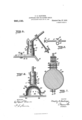
- Figure 1 is a side elevation showing the form of bracket which adapts the device for attaching the same to a beam such as an I- beam;
- Fig. 2 is a vertical section taken on the line 2-2 of Fig. 1 and showing further details of the post and bracket;
- Fig. 3 is a side elevation of an adjustable stem which is attached to the post;
- Fig. 4 is a vertical section through an angle iron, and showing the form of bracket I employ when adapting the device for attachment to a beam of this form;
- Fig. 5 is a vertical section through a steel structural member of special form and showing another form of the means for securing the device, this view illustrating particularly the adjustability of the device;
- Fig. 1 is a side elevation showing the form of bracket which adapts the device for attaching the same to a beam such as an I- beam;
- Fig. 2 is a vertical section taken on the line 2-2 of Fig. 1 and showing further details of the post and bracket;
- Fig. 3 is a side elevation of an
- FIG. 6 is avertical section through the base of a fastening foot of pneumatic type and illustrating how the device may be applied to the surface of a plate
- Fig. 7 is a cross section through a column, illustrating the manner in which the device may be attached to a member of this form
- Fig. 8 is a detail plan showing an adjustable arm which is attached to the stem shown in Fig. 3.
- the device comprises a post 1, of cylindrical or round form,
- the stem 1 has an enlarged semi-circular head 6 which lies in the slot 2, and this head is provided near its rim with a plurality of circumferentially disposed openings 7.
- the ears 3 are further provided with a removable locking pin 8 which is adapted to be removed and passed through any one of the openings 7. By placing this locking pin 8 in different openings, different locked positions of the stem 4 may be obtained.
- the post 1 may be secured rigidly to an I-beam by means of two clamps 9, the lower ends of which are offset away from each other so as to form jaws 10 adapted to engage the edges of the flange 11. of the I-beam, as indicated most clearly in Fig. 2.
- the lower part of the post is provided with a pair of parallel openings 12, lying in the same plane, which pass diametrically through the post so as to receive clamping bolts 13 and 14 which pass through the post and through the clam s, as indicated.
- the up er one of these ad justing bolts is provide with a nut 15 which is adapted to clamp against the side of the post so as to secure it firmly against one of the clamps.
- a sliding arm 17 On the stem 4 there is provided a sliding arm 17, the inner end of which is formed into a sleeve 18 which receives the stem, as shown.
- This sleeve is provided with a clamping screw 19 which enables the arm to be secured to the stem at any point desired.
- I provide a second pair of openings 20 which pass through the post in a plane at right angles to the plane passing through the openings 12.
- the post 1 may be held between the clamps in two definite positions at right angles to each other. WVhile the post is in one of these positions (see Figs. 1 and 2) the sector 6 lies in a i S S: 1
- Fig. 4 I illustrate the manner in which the bracket is constructed when the device is to be attached to an angle iron 21 having a horizontal flange 22.
- I provide a pair of angle brackets or clips 23 and '24, the latter of which preferably has a wider web 25 than the web 26 of the bracket 23.
- the angle brackets or clips 23 and 24 are then applied to the flange of the beam, as indicated, the angle bracket 24 being arranged so that its web 25 is applied to the under side of the flange 22.
- the angle bracket then presents an upwardly extending flange 27 which is disposed opposite to the upwardly extending flange 28 of the angle bracket 23.
- the flanges 27 and 28 are connected by clamping bolts 29 and 30 which are constructed and arranged similar to the bolts 13 and 14, that is, the upper bolt 29 carries a nut 31 which clamps the side of the post 32, while both of the bolts carry nuts 33 which afford means for drawing the clamps toward each other.
- the post and various other parts shown in this construction are identical with those appearing in Fig. 2.
- the flange 26 of the upper angle bracket 23 which seats upon the upper side of the flange 22 is provided with a set screw or clamping screw 34 which passes downwardly through the web 26 so that its point comes against the upper side of the flange 22.
- a sliding sleeve 38 On the arm 17 there is mounted a sliding sleeve 38, the details of which are clearly shown in Fig. 8.
- This sliding sleeve is provided on one side with a clamping screw 39 which is adapted to engage the side of the arm so as to hold the sleeve rigidly thereto.
- This sliding sleeve 38 carries a center screw 40, the end of which is adapted to form a back center for a ratchet drill 41 mounted as shown in Fig. 1.
- Fig. 1 shows how the device may be used for drilling a hole in a vertical plane, that is,
- FIG. 5 1 illustrate how the device can be adjusted so as to drill a hole in an inclined flange or plate 42 which is supposed to be connected with a plate 43 which may be horizontal, as shown.
- the locking pin 45 will be removed and the stem 44 will be shifted into substantially the position shown, and the pin will then be replaced.
- the stem should be substantially at right angles to the surface of the flange 42 and the sleeve 46 can then be run out on the arm 47 to any point desired.
- a special bracket 48 having a foot 49 in the form of a plate which rests upon the upper side of the plate 43, said plate having an adjusting slot 50 which runs longitudinally of the plat-e. Through this slot passes an adjusting bolt 51.
- the special bracket 48 is provided with an enlarged socket 52 which receives the lower end of the post 53, as shown.
- two pairs of openings 54 are provided, in either pair of which removable bolts 55 may be received, as indicated. This enables the post to be sw'u'ng around so that the stem 44 may be swung in a plane at right angles to its normal position, as suggested above.
- a beam or plate such as described above, to which the device may be attached.
- This post is also provided with two pairs of openings 61 disposed in planes at right angles to each other;
- the lower portion of the socket 57 is expanded so as to form a substantially hemispherical shell or bonnet 62, and to the inner side of this bonnet a cup 63 is secured, said cup being formed of hard rubber.
- the body of this cup is of hemispherical form so as to fit nicely to the curvature of the bonnet 62, but its edge projects downwardly below the edge of the bonnet and is turned outwardly so as to form a broad mouth or flange 64 which seats on the surface of the plate, as shown.
- the interior of the cup forms a vacuum chamber 65 from which the air may be exhausted through a hose connection 66 and to which air may be admitted through a valve 67. It will be evident that when the air is exhausted from the vacuum chamber, the atmospheric pressure on the post and the bonnet will force the base of the post be adjusted into any downwardl and hold the same securely on the plate; t e stem 68 of the device may then osition desired.
- a column 69 such as shown in Fig. 7, I provide a split ring formed of two sections 70 having small ears 71 at one side connected by an adjusting bolt 72.
- this post has two pairs of parallel bolt openings 77 disposed in planes at right angles to each other so that the post may be shifted through 90, enabling the stem 78 to swing down in either of two planes at right angles to each other.
- a device of the class described comprising a post having a pair of openings tical plane forming an angle with said first vertical plane, means for rigidly securing said post to the work near the point of application of the drill, said means having bolts passing therethrough and adapted to pass through either pair of said openings, whereby said post may be held in different angular positions with respect to the vertical axis thereof, an adjustable arm carried by said post, and means on said arm for adjustably supporting the butt end of a drill.
- a device of the character described comprising a 0st provided with a number of holes exten ing iametrically through it, different groups of said holes being arranged in definite planes, a plane corresponding to one group of said holes crossing another plane corresponding to another group of said holes, bolts for extending through said holes, stationary members for engagjng said bolts, said stationary members eing for this purpose provided with holes arranged in a definite plane so that a plurality of said bolts may be used for holdmg said post relatively to said stationary members, a rigid drill, and means on said post for adjustably supporting the butt end of a drill.
Landscapes
- Engineering & Computer Science (AREA)
- Mechanical Engineering (AREA)
- Mining & Mineral Resources (AREA)
- Mutual Connection Of Rods And Tubes (AREA)
Description
Patented Dec.27, 1910.
2 SHEETS-SHEET 1.
INVENTO/f 6% a'z-Zeo 17. Elsi/II a;
WITNESSES Q QLMM B 7% @h M LM 0 ATTORNEYS 0. B. HASTINGS.
ADJUSTABLE POST FOR RATGHET DRILLS. APPLICATION FILED AUG. 25, 1909.
Patented Dec. 27, 1910.
$2; 156 WITNESSES m/m/mn Cfiajlg s .1? Hash) GFKMTMM %I7% ATTORNEYS CHARLES B. HASTINGS, OF NEW YORK, N. Y.
ADJUSTABLE POST FOR RATCHET-DRILLS.
Specification of Letters Patent.
Patented Dec. 27, 1910.
Application filed August 25, 1909. Serial No. 514,531.
To all whom it may concern:
Be it known that I, CHARLES B. HASTINGS, a citizen of the United States, and a resident of the city of New York, borough of Manhattan, in the county and State of New York, have invented a new and Im roved Adjustable Post for Ratchet-Drills, 0 which the following is a full, clear, and exact description.
This invention relates to a holder for ratchet drills such as are used largely in steel construction for drilling holes in the work.
The object of this invention is to produce a holding device for a ratchet drill, which can be attached to a beam or plate and which will afford means for holding the ratchet drill at any inclination and in substantially any position within the range of the device.
The invention consists in the construction and combination of parts to be more fully described hereinafter and particularly set forth in the claims.
Reference is to be had to the accompanying drawings forming a part of this specification, in which similar characters of reference indicate corresponding parts in all the figures.
Figure 1 is a side elevation showing the form of bracket which adapts the device for attaching the same to a beam such as an I- beam; Fig. 2 is a vertical section taken on the line 2-2 of Fig. 1 and showing further details of the post and bracket; Fig. 3 is a side elevation of an adjustable stem which is attached to the post; Fig. 4 is a vertical section through an angle iron, and showing the form of bracket I employ when adapting the device for attachment to a beam of this form; Fig. 5 is a vertical section through a steel structural member of special form and showing another form of the means for securing the device, this view illustrating particularly the adjustability of the device; Fig. 6 is avertical section through the base of a fastening foot of pneumatic type and illustrating how the device may be applied to the surface of a plate; Fig. 7 is a cross section through a column, illustrating the manner in which the device may be attached to a member of this form; and Fig. 8 is a detail plan showing an adjustable arm which is attached to the stem shown in Fig. 3.
, Referring more particularly to the parts, and especially to Fig. 1, the device comprises a post 1, of cylindrical or round form,
the upper end of which is provided with a transverse slot 2 so that the upper end of the post presents oppositely disposed ears 3. Between these ears a stem 4 is rotatably mounted on a pivot pin or screw 5. The stem 1 has an enlarged semi-circular head 6 which lies in the slot 2, and this head is provided near its rim with a plurality of circumferentially disposed openings 7. The ears 3 are further provided with a removable locking pin 8 which is adapted to be removed and passed through any one of the openings 7. By placing this locking pin 8 in different openings, different locked positions of the stem 4 may be obtained. The post 1 may be secured rigidly to an I-beam by means of two clamps 9, the lower ends of which are offset away from each other so as to form jaws 10 adapted to engage the edges of the flange 11. of the I-beam, as indicated most clearly in Fig. 2. The lower part of the post is provided with a pair of parallel openings 12, lying in the same plane, which pass diametrically through the post so as to receive clamping bolts 13 and 14 which pass through the post and through the clam s, as indicated. The up er one of these ad justing bolts is provide with a nut 15 which is adapted to clamp against the side of the post so as to secure it firmly against one of the clamps. The ends of these bolts 13 and 14 pass through one of the clamps and are provided on their outer portions with nuts 16 which are adapted to draw the clamps together so as to engage the edges of the flange 11., as will be readily understood. \Vith this arrangement it will be seen that the post can be firmly held between the clamps and the clamps can be securely held on the beam.
On the stem 4 there is provided a sliding arm 17, the inner end of which is formed into a sleeve 18 which receives the stem, as shown. This sleeve is provided with a clamping screw 19 which enables the arm to be secured to the stem at any point desired. Referring again to Fig. 2, in addition to the pair of openings 12, I provide a second pair of openings 20 which pass through the post in a plane at right angles to the plane passing through the openings 12. By reason of these openings 20, the post 1 may be held between the clamps in two definite positions at right angles to each other. WVhile the post is in one of these positions (see Figs. 1 and 2) the sector 6 lies in a i S S: 1
plane coinciding with the general plane of the rail 11. In the other position, however, the sector 6 crosses this plane. It should be noted that these openings 20 are represented as above the openings 12 respectively, in Fig. 2, and in this position of the post the lower face of the post is slightly elevated above the upper face of the beam, which permits the post to be adjusted downwardly as suggested. In neither of the positions of the post is it necessary for the post to seat its lower end upon the beam. Its rigidity is secured entirely by the clamps. In this connection it should be understood that the openings 12 and 20 fit the bolts nicely, so
that when the nut 15 is tightened. the post becomes very secure and rigid. It should be noted also that the clamps effectually prevent any tendency of the device to shift longitudinally of the beam.
In Fig. 4 I illustrate the manner in which the bracket is constructed when the device is to be attached to an angle iron 21 having a horizontal flange 22. In order to attach the device to such a structural shape, I provide a pair of angle brackets or clips 23 and '24, the latter of which preferably has a wider web 25 than the web 26 of the bracket 23. The angle brackets or clips 23 and 24 are then applied to the flange of the beam, as indicated, the angle bracket 24 being arranged so that its web 25 is applied to the under side of the flange 22. The angle bracket then presents an upwardly extending flange 27 which is disposed opposite to the upwardly extending flange 28 of the angle bracket 23. The flanges 27 and 28 are connected by clamping bolts 29 and 30 which are constructed and arranged similar to the bolts 13 and 14, that is, the upper bolt 29 carries a nut 31 which clamps the side of the post 32, while both of the bolts carry nuts 33 which afford means for drawing the clamps toward each other. The post and various other parts shown in this construction are identical with those appearing in Fig. 2. The flange 26 of the upper angle bracket 23 which seats upon the upper side of the flange 22 is provided with a set screw or clamping screw 34 which passes downwardly through the web 26 so that its point comes against the upper side of the flange 22.
On the arm 17 there is mounted a sliding sleeve 38, the details of which are clearly shown in Fig. 8. This sliding sleeve is provided on one side with a clamping screw 39 which is adapted to engage the side of the arm so as to hold the sleeve rigidly thereto. This sliding sleeve 38 carries a center screw 40, the end of which is adapted to form a back center for a ratchet drill 41 mounted as shown in Fig. 1.
Fig. 1 shows how the device may be used for drilling a hole in a vertical plane, that is,
drilling a hole in the upper face of a horizontal beam. In Fig. 5 1 illustrate how the device can be adjusted so as to drill a hole in an inclined flange or plate 42 which is supposed to be connected with a plate 43 which may be horizontal, as shown. In order to adapt the drill holder to operate on the flange 42, the locking pin 45 will be removed and the stem 44 will be shifted into substantially the position shown, and the pin will then be replaced. The stem should be substantially at right angles to the surface of the flange 42 and the sleeve 46 can then be run out on the arm 47 to any point desired. In such a situation as this I may use a special bracket 48 having a foot 49 in the form of a plate which rests upon the upper side of the plate 43, said plate having an adjusting slot 50 which runs longitudinally of the plat-e. Through this slot passes an adjusting bolt 51. At one end of the foot 49 the special bracket 48 is provided with an enlarged socket 52 which receives the lower end of the post 53, as shown. In this post 53, two pairs of openings 54 are provided, in either pair of which removable bolts 55 may be received, as indicated. This enables the post to be sw'u'ng around so that the stem 44 may be swung in a plane at right angles to its normal position, as suggested above.
Under some circumstances it may be impossible to find a beam or plate such as described above, to which the device may be attached. For instance, it may be necessary to attach it to the upper surface of a smooth plate 56, as illustrated in Fig.6. In order to adapt the device for attachment to such a plate, I provide a socket 57 which receives the lower end of the post 58, as shown, and this socket is provided with pins 59 and 60 which pass through it and through the post so as to secure the post in position, as indicated. This post is also provided with two pairs of openings 61 disposed in planes at right angles to each other; The lower portion of the socket 57 is expanded so as to form a substantially hemispherical shell or bonnet 62, and to the inner side of this bonnet a cup 63 is secured, said cup being formed of hard rubber. The body of this cup is of hemispherical form so as to fit nicely to the curvature of the bonnet 62, but its edge projects downwardly below the edge of the bonnet and is turned outwardly so as to form a broad mouth or flange 64 which seats on the surface of the plate, as shown. The interior of the cup forms a vacuum chamber 65 from which the air may be exhausted through a hose connection 66 and to which air may be admitted through a valve 67. It will be evident that when the air is exhausted from the vacuum chamber, the atmospheric pressure on the post and the bonnet will force the base of the post be adjusted into any downwardl and hold the same securely on the plate; t e stem 68 of the device may then osition desired. Where the device is to be attached to a column 69 such as shown in Fig. 7, I provide a split ring formed of two sections 70 having small ears 71 at one side connected by an adjusting bolt 72. At the other side the ends of the sections 70 are extended so as to form large ears 73, between which the post is clamped by means of two clamping bolts 75. These bolts pass through the ears and through the post, so that when the nuts 76 are tightened up the post will be securely clamped to the ring. As in the other forms descrlbed, this post has two pairs of parallel bolt openings 77 disposed in planes at right angles to each other so that the post may be shifted through 90, enabling the stem 78 to swing down in either of two planes at right angles to each other.
Having thus described my invention, I claim as new and desire to secure by Letters l. A device of the class described, comprising a post having a pair of openings tical plane forming an angle with said first vertical plane, means for rigidly securing said post to the work near the point of application of the drill, said means having bolts passing therethrough and adapted to pass through either pair of said openings, whereby said post may be held in different angular positions with respect to the vertical axis thereof, an adjustable arm carried by said post, and means on said arm for adjustably supporting the butt end of a drill.
2. A device of the character described, comprising a 0st provided with a number of holes exten ing iametrically through it, different groups of said holes being arranged in definite planes, a plane corresponding to one group of said holes crossing another plane corresponding to another group of said holes, bolts for extending through said holes, stationary members for engagjng said bolts, said stationary members eing for this purpose provided with holes arranged in a definite plane so that a plurality of said bolts may be used for holdmg said post relatively to said stationary members, a rigid drill, and means on said post for adjustably supporting the butt end of a drill.
In testimony whereof I have signed my name to this s ecification in the presence of two subscribing witnesses.
CHARLES E. HASTINGS.
\Vitnesses:
BENJAMIN Moms, ISAAC PINNER.
Priority Applications (1)
| Application Number | Priority Date | Filing Date | Title |
|---|---|---|---|
| US51453109A US980100A (en) | 1909-08-25 | 1909-08-25 | Adjustable post for ratchet-drills. |
Applications Claiming Priority (1)
| Application Number | Priority Date | Filing Date | Title |
|---|---|---|---|
| US51453109A US980100A (en) | 1909-08-25 | 1909-08-25 | Adjustable post for ratchet-drills. |
Publications (1)
| Publication Number | Publication Date |
|---|---|
| US980100A true US980100A (en) | 1910-12-27 |
Family
ID=3048474
Family Applications (1)
| Application Number | Title | Priority Date | Filing Date |
|---|---|---|---|
| US51453109A Expired - Lifetime US980100A (en) | 1909-08-25 | 1909-08-25 | Adjustable post for ratchet-drills. |
Country Status (1)
| Country | Link |
|---|---|
| US (1) | US980100A (en) |
Cited By (2)
| Publication number | Priority date | Publication date | Assignee | Title |
|---|---|---|---|---|
| US2468358A (en) * | 1945-03-09 | 1949-04-26 | Francis E Clark | Power drill holder |
| US3195375A (en) * | 1962-08-01 | 1965-07-20 | Western Pennsylvania Nat Bank | Portable drills |
-
1909
- 1909-08-25 US US51453109A patent/US980100A/en not_active Expired - Lifetime
Cited By (2)
| Publication number | Priority date | Publication date | Assignee | Title |
|---|---|---|---|---|
| US2468358A (en) * | 1945-03-09 | 1949-04-26 | Francis E Clark | Power drill holder |
| US3195375A (en) * | 1962-08-01 | 1965-07-20 | Western Pennsylvania Nat Bank | Portable drills |
Similar Documents
| Publication | Publication Date | Title |
|---|---|---|
| US688230A (en) | Adjustable holder for embroidery-hoops. | |
| US10907756B2 (en) | Clamp apparatus and method for joining pipeline segments | |
| US1811518A (en) | Clamp | |
| US1578634A (en) | Clamping and supporting device | |
| US10681986B1 (en) | Systems and methods for manicure head rests | |
| US1543037A (en) | Adjustable light fixture | |
| US1319900A (en) | Clamp. | |
| US890656A (en) | Table attachment for chairs, &c. | |
| US980100A (en) | Adjustable post for ratchet-drills. | |
| US504717A (en) | Umbrella-support | |
| US1228083A (en) | Copy-holder. | |
| US972989A (en) | Adjustable post-support. | |
| US3152784A (en) | Pipe support | |
| US1086375A (en) | Adjustable boiler-stand. | |
| US930687A (en) | Adjustable vise. | |
| US1199479A (en) | Tool-holder. | |
| US1060574A (en) | Attachment for drill-presses. | |
| US600100A (en) | George f | |
| US1319179A (en) | Saw-gage | |
| US237331A (en) | Half to heemaist funke | |
| US1330318A (en) | Support | |
| US745346A (en) | Lathe-chuck. | |
| US259603A (en) | John thomson | |
| US259945A (en) | Hugh thomas | |
| US316666A (en) | Heney c |