US9799433B2 - Superconducting magnet - Google Patents
Superconducting magnet Download PDFInfo
- Publication number
- US9799433B2 US9799433B2 US14/903,459 US201314903459A US9799433B2 US 9799433 B2 US9799433 B2 US 9799433B2 US 201314903459 A US201314903459 A US 201314903459A US 9799433 B2 US9799433 B2 US 9799433B2
- Authority
- US
- United States
- Prior art keywords
- refrigerant
- current lead
- container
- current
- superconducting coil
- Prior art date
- Legal status (The legal status is an assumption and is not a legal conclusion. Google has not performed a legal analysis and makes no representation as to the accuracy of the status listed.)
- Active, expires
Links
Images


Classifications
-
- H—ELECTRICITY
- H01—ELECTRIC ELEMENTS
- H01F—MAGNETS; INDUCTANCES; TRANSFORMERS; SELECTION OF MATERIALS FOR THEIR MAGNETIC PROPERTIES
- H01F6/00—Superconducting magnets; Superconducting coils
- H01F6/04—Cooling
-
- A—HUMAN NECESSITIES
- A61—MEDICAL OR VETERINARY SCIENCE; HYGIENE
- A61B—DIAGNOSIS; SURGERY; IDENTIFICATION
- A61B5/00—Measuring for diagnostic purposes; Identification of persons
- A61B5/05—Detecting, measuring or recording for diagnosis by means of electric currents or magnetic fields; Measuring using microwaves or radio waves
- A61B5/055—Detecting, measuring or recording for diagnosis by means of electric currents or magnetic fields; Measuring using microwaves or radio waves involving electronic [EMR] or nuclear [NMR] magnetic resonance, e.g. magnetic resonance imaging
-
- G—PHYSICS
- G01—MEASURING; TESTING
- G01R—MEASURING ELECTRIC VARIABLES; MEASURING MAGNETIC VARIABLES
- G01R33/00—Arrangements or instruments for measuring magnetic variables
- G01R33/20—Arrangements or instruments for measuring magnetic variables involving magnetic resonance
- G01R33/28—Details of apparatus provided for in groups G01R33/44 - G01R33/64
- G01R33/38—Systems for generation, homogenisation or stabilisation of the main or gradient magnetic field
- G01R33/3804—Additional hardware for cooling or heating of the magnet assembly, for housing a cooled or heated part of the magnet assembly or for temperature control of the magnet assembly
-
- G—PHYSICS
- G01—MEASURING; TESTING
- G01R—MEASURING ELECTRIC VARIABLES; MEASURING MAGNETIC VARIABLES
- G01R33/00—Arrangements or instruments for measuring magnetic variables
- G01R33/20—Arrangements or instruments for measuring magnetic variables involving magnetic resonance
- G01R33/28—Details of apparatus provided for in groups G01R33/44 - G01R33/64
- G01R33/38—Systems for generation, homogenisation or stabilisation of the main or gradient magnetic field
- G01R33/381—Systems for generation, homogenisation or stabilisation of the main or gradient magnetic field using electromagnets
- G01R33/3815—Systems for generation, homogenisation or stabilisation of the main or gradient magnetic field using electromagnets with superconducting coils, e.g. power supply therefor
-
- H—ELECTRICITY
- H01—ELECTRIC ELEMENTS
- H01F—MAGNETS; INDUCTANCES; TRANSFORMERS; SELECTION OF MATERIALS FOR THEIR MAGNETIC PROPERTIES
- H01F6/00—Superconducting magnets; Superconducting coils
-
- H—ELECTRICITY
- H01—ELECTRIC ELEMENTS
- H01F—MAGNETS; INDUCTANCES; TRANSFORMERS; SELECTION OF MATERIALS FOR THEIR MAGNETIC PROPERTIES
- H01F6/00—Superconducting magnets; Superconducting coils
- H01F6/006—Supplying energising or de-energising current; Flux pumps
- H01F6/008—Electric circuit arrangements for energising superconductive electromagnets
-
- H—ELECTRICITY
- H01—ELECTRIC ELEMENTS
- H01F—MAGNETS; INDUCTANCES; TRANSFORMERS; SELECTION OF MATERIALS FOR THEIR MAGNETIC PROPERTIES
- H01F6/00—Superconducting magnets; Superconducting coils
- H01F6/02—Quenching; Protection arrangements during quenching
-
- H—ELECTRICITY
- H01—ELECTRIC ELEMENTS
- H01F—MAGNETS; INDUCTANCES; TRANSFORMERS; SELECTION OF MATERIALS FOR THEIR MAGNETIC PROPERTIES
- H01F6/00—Superconducting magnets; Superconducting coils
- H01F6/06—Coils, e.g. winding, insulating, terminating or casing arrangements therefor
Definitions
- the present invention relates to a superconducting magnet, and particularly to a superconducting magnet having a current lead of a fixed type.
- Japanese Patent Laying-Open No. 2-000306 (PTD 1) is provided.
- the current lead has a high thermal conductivity resistance. This reduces a quantity of heat introduced through the current lead when a magnetic coil is in a continuation mode (a mode in which a current does not flow through the current lead).
- a continuation mode a mode in which a current does not flow through the current lead.
- helium gas flows from a refrigerant container through the current lead, so that the current lead is cooled automatically.
- PTD 1 Japanese Patent Laying-Open No. 2-000306
- a flow rate of helium gas flowing through the current lead is adjusted by controlling opening and closing of a solenoid valve by means of a solenoid coil.
- the present invention was made in view of the problem described above, and its object is to provide a superconducting magnet capable of preventing burn-out of a current lead.
- a superconducting magnet in accordance with the present invention comprises a superconducting coil, a refrigerant container accommodating the superconducting coil which is in a state of being immersed in a liquid refrigerant, a radiation shield surrounding the refrigerant container, a vacuum container accommodating the superconducting coil, the refrigerant container, and the radiation shield, a refrigerating machine cooling an interior of the refrigerant container and the radiation shield, a tubular current lead passing from outside of the vacuum container to inside of the refrigerant container to constitute a flow path of said gasified refrigerant and electrically connected to the superconducting coil, a power source arranged outside of the vacuum container and electrically connected to the current lead, a manometer measuring a pressure inside of the refrigerant container, a thermometer arranged in the vacuum container to measure a temperature of the current lead, and a control unit connected to each of the power source, the manometer, and the thermometer.
- the control unit raises an output of the power source to vary a value of a current flowing into the superconducting coil only when a measurement value of the manometer is higher than or equal to a set value and a measurement value of the thermometer is lower than or equal to a set value.
- burn-out of the current lead can be prevented.
- FIG. 1 is a perspective view representing an appearance of an MRI apparatus.
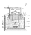
- FIG. 2 is a cross-sectional view representing a structure of a superconducting magnet in accordance with a first embodiment of the present invention.
- FIG. 3 is a cross-sectional view representing a configuration of the superconducting magnet in accordance with the same embodiment.
- FIG. 4 represents a temperature dependency in a value of a product of a thermal conductivity and an electrical resistivity for each of phosphorous deoxidized copper, brass, electrolytic copper, and SUS304.
- FIG. 5 is a cross-sectional view representing a configuration of a superconducting magnet in accordance with a second embodiment of the present invention.
- FIG. 6 is a cross-sectional view representing a configuration of a superconducting magnet in accordance with a third embodiment of the present invention.
- FIG. 7 is a cross-sectional view representing a configuration of a superconducting magnet in accordance with a fourth embodiment of the present invention.
- the superconducting magnet for MRI (Magnetic Resonance Imaging) will be described in the following embodiment, the superconducting magnet is not limited to this usage and may be used for other usage.
- a superconducting magnet of a cylindrical type will be described, it is not limited to the superconducting magnet of the cylindrical type, and the present invention can be applied also to a superconducting magnet of an open type.
- FIG. 1 is a perspective view representing an appearance of an MRI apparatus.
- an MRI apparatus 1 includes a static magnetic field generating unit 10 and a bed 30 .
- Static magnetic field generating unit 10 includes a superconducting magnet, which will be described later, and generates a static magnetic field inside of a bore 20 .
- FIG. 2 is a cross-sectional view representing a structure of the superconducting magnet in accordance with the first embodiment of the present invention.
- a vacuum container 110 having a hollow cylindrical shape is arranged on an outermost side.
- Vacuum container 110 is constituted of nonmagnetic material such as stainless steel or aluminum to provide vacuum insulation between inside and outside of vacuum container 110 .
- a space in a cylinder center portion of vacuum container 110 is a bore portion corresponding to bore 20 .
- the interior of vacuum container 110 is decompressed by a decompression device, which is not illustrated in the drawings, to provide vacuum.
- Vacuum container 110 is supported by a leg portion arranged on a lower portion such that a center axis of the bore portion is oriented in a horizontal direction.
- a radiation shield 120 is arranged, which has a hollow cylindrical shape substantially similar to vacuum container 110 .
- Radiation shield 120 is constituted of, for example, nonmagnetic material such as aluminum exhibiting a high light reflectance.
- multilayer heat insulating material (superinsulation), which is not illustrated in the drawings, is attached.
- a refrigerant container 130 is arranged, which has a hollow cylindrical shape substantially similar to radiation shield 120 .
- Radiation shield 120 surrounds refrigerant container 130 and serves to provide heat insulation between refrigerant container 130 and vacuum container 110 .
- Refrigerant container 130 is constituted of nonmagnetic material such as stainless steel or aluminum.
- a superconducting coil 140 is accommodated in refrigerant container 130 .
- Superconducting coil 140 is wound at a bottom portion of refrigerant container 130 serving also as a winding frame.
- Refrigerant container 130 is filled with liquid helium 150 as a liquid refrigerant.
- Superconducting coil 140 is immersed in liquid helium 150 and cooled.
- Superconducting coil 140 is constituted of, for example, a wound superconducting wire which is formed by embedding niobium titanium alloy in a center portion of a matrix made of copper.
- vacuum container 110 accommodates superconducting coil 140 , refrigerant container 130 , and radiation shield 120 .
- a static magnetic field 50 in the arrow direction is generated in a static magnetic field region 40 in the area of the bore portion indicated by the dotted line in the drawing.
- FIG. 3 is a cross-sectional view representing a configuration of the superconducting magnet in accordance with the present embodiment. In FIG. 3 , each configuration is illustrated in a simplified manner for simplification.
- a disturbance magnetic field compensating coil 141 for suppressing influence of a disturbance magnetic field with respect to superconducting coil 140 is arranged outside of superconducting coil 140 .
- Disturbance magnetic field compensating coil 141 is constituted of, for example, a wound superconducting wire which is formed by embedding niobium titanium alloy in a center portion of a matrix made of copper.
- first persistent current switch 170 is connected to superconducting coil 140 electrically in serial.
- First persistent current switch 170 is constituted of, for example, a winding wire of a superconducting filament made of niobium titanium alloy and wound around a winding frame made of epoxy resin.
- a first resistive heating heater 171 having a heater wire wound therearound is arranged outside of first persistent current switch 170 .
- a second persistent current switch 160 is connected to disturbance magnetic field compensating coil 141 electrically in serial.
- Second persistent current switch 160 is constituted of, for example, a winding wire of a superconducting filament made of niobium titanium alloy and wound around a winding frame made of epoxy resin.
- Second resistive heating heater 161 having a heater wire wound therearound is arranged outside of second persistent current switch 160 .
- Superconducting magnet 100 in accordance with the present embodiment further includes a third resistive heating heater 181 which is arranged in refrigerant container 130 and gasifies liquid helium 150 . It should be noted that, when electrical conduction to second resistive heating heater 161 can gasify a quantity of liquid helium 150 required to cool current lead 190 at the time of magnetizing and demagnetizing superconducting magnet 100 as described below, it is not necessary to provide third resistive heating heater 181 .
- Each of disturbance magnetic field compensating coil 141 , first persistent current switch 170 , first resistive heating heater 171 , second persistent current switch 160 , second resistive heating heater 161 , and third resistive heating heater 181 is immersed in liquid helium 150 in refrigerant container 130 .
- Superconducting magnet 100 includes a refrigerating machine 180 for cooling an interior of refrigerant container 130 and radiation shield 120 .
- refrigerating machine 180 a Gifford-MacMahon type refrigerating machine or a pulse tube refrigerating machine having two refrigerating stages can be used.
- a first refrigerating stage of refrigerating machine 180 is thermally in contact with radiation shield 120 .
- a second refrigerating stage of refrigerating machine 180 is located at an upper portion in refrigerant container 130 and re-liquefies gasified helium gas 151 .
- Superconducting magnet 100 includes two tubular current leads 190 passing from outside of vacuum container 110 to inside of refrigerant container 130 to constitute flow paths of helium gas 151 and electrically connected to superconducting coil 140 .
- Each current lead 190 has a straight-pipe outer shape, and only an upper end portion of current lead 190 is located outside of vacuum container 110 .
- material of current lead 190 contains phosphorous deoxidized copper as a main component.
- the main component of the material of current lead 190 is not limited to phosphorous deoxidized copper, and it may be brass or electrolytic copper.
- each current lead 190 is cooled to about 4K which is substantially the same as superconducting coil 140 .
- Each current lead 190 is fixed in a state of being inserted to an annular fixation member 111 , which is provided in vacuum container 110 and has an electrical insulation property.
- the exterior of vacuum container 110 is at a temperature of about 300K which is a room temperature.
- a mid-temperature stage 121 for example, made of copper and having a block-like shape is connected to each current lead 190 at a position of about one-third of an overall length of current lead 190 on a lower end side of current lead 190 from a portion in contact with fixation member 111 .
- Each mid-temperature stage 121 is thermally in contact with radiation shield 120 while clamping a thermal anchor therebetween.
- Each mid-temperature stage 121 and radiation shield 120 are electrically insulated.
- a thermometer 122 arranged in vacuum container 110 for measuring the temperature of current lead 190 is connected to each mid-temperature stage 121 .
- a platinum resistance thermometer exhibiting a favorable measurement accuracy in a cryogenic temperature region is used as thermometer 122 .
- a thermoelectric couple may be used.
- An external pipe 191 which is in communication with current lead 190 and has an electrical insulation property, is connected to an upper end portion of each current lead 190 .
- two current leads 190 and one branched external pipe 191 are connected.
- An open valve for opening and closing external pipe 191 is provided at an unbranched portion of external pipe 191 .
- a check valve or an electromagnetic valve can be used as open valve 192 .
- Superconducting magnet 100 includes a manometer 198 for measuring the pressure inside of refrigerant container 130 .
- Manometer 198 measures the pressure of helium gas 151 in refrigerant container 130 .
- superconducting magnet 100 includes a power source 193 arranged outside of vacuum container 110 and electrically connected to each current lead 190 .
- superconducting magnet 100 includes a control unit 199 connected to each of power source 193 , manometer 198 , and two thermometers 122 .
- Control unit 199 is arranged outside of vacuum container 110 .
- a measurement value of each thermometer 122 and a measurement value of manometer 198 are inputted to control unit 199 .
- Control unit 199 is electrically connected to each of first resistive heating heater 171 , second resistive heating heater 161 , and third resistive heating heater 181 . Therefore, each of first resistive heating heater 171 , second resistive heating heater 161 , and third resistive heating heater 181 is connected to power source 193 through control unit 199 .
- superconducting magnet 100 may have a function to measure the liquid amount of liquid helium 150 in refrigerant container 130 , a function to measure the temperature of radiation shield 120 , a function to measure the temperature of the second refrigerating stage of refrigerating machine 180 , a function to shut off the magnetic field generated by superconducting coil in emergency, a function to control a compressor of refrigerating machine 180 , or the like.
- the first refrigerating stage of refrigerating machine 180 cools radiation shield 120 to about 50K.
- Superconducting coil 140 is cooled by liquid nitrogen to about 77K.
- helium gas fills refrigerant container 130 to replace nitrogen.
- superconducting coil 140 is cooled by liquid helium 150 to about 4K.
- control unit 199 allows a current from power source 193 to flow into each of first resistive heating heater 171 and second resistive heating heater 161 . Accordingly, a resistance is generated in a superconducting filament of each of first persistent current switch 170 and second persistent current switch 160 .
- Generating the resistance in the superconducting filament of second persistent current switch 160 reduces a current induced by disturbance magnetic field compensating coil 141 due to an influence of the magnetic field received from the disturbance magnetic field, so that an output of disturbance magnetic field compensating coil 141 is reset.
- control unit 199 allows a current from power source 193 to flow into third resistive heating heater 181 . Accordingly, liquid helium 150 is evaporated by Joule's heat of third resistive heating heater 181 , so that the pressure in refrigerant container 130 is raised. At this time, open valve 192 is in an open state.
- conditions for starting magnetization are set and inputted to control unit 199 .
- the conditions are defined that a measurement value of manometer 198 is higher than or equal to a gauge pressure of 7000 Pa and a measurement value of each thermometer 122 is lower than or equal to 80K.
- control unit 199 raises an output of power source 193 to vary a value of a current flowing into superconducting coil 140 only when a measurement value of manometer 198 is higher than or equal to a set value and a measurement value of thermometer 122 is lower than or equal to a set value.
- control unit 199 determines that magnetization cannot be performed, and it does not raise an output of power source 193 .
- control unit 199 raises an output of power source 193 , almost no current flows into first persistent current switch 170 in which the resistance is generated, and a current mainly flows into superconducting coil 140 through current lead 190 .
- control unit 199 recognizing that the temperature of mid-temperature stage 121 became higher than 80K based on the inputted measurement value of thermometer 122 stops the rise in an output of power source 193 . Accordingly, burn-out of current lead 190 due to overheating is prevented.
- control unit 199 stops electric conduction to first resistive heating heater 171 . Accordingly, first persistent current switch 170 is cooled by liquid helium 150 to be in a superconducting state.
- control unit 199 lowers an output of power source 193 .
- the amount of current flowing in superconducting coil 140 is not varied, and the amount of current flowing in first persistent current switch 170 increases.
- the output of power source 193 becomes zero, the same amount of current flows into superconducting coil 140 and first persistent current switch 170 .
- a current flows continuously in a closed loop constituted of superconducting coil 140 and first persistent current switch 170 . Accordingly, the magnetization of superconducting magnet 100 is completed.
- control unit 199 allows a current from power source 193 to flow into second resistive heating heater 161 . Accordingly, a resistance is generated in a superconducting filament of second persistent current switch 160 . Generating the resistance in the superconducting filament of second persistent current switch 160 reduces a current induced by disturbance magnetic field compensating coil 141 due to an influence of the magnetic field from disturbance magnetic field, so that the output of disturbance magnetic field compensating coil 141 is reset.
- control unit 199 allows a current from power source 193 to flow into third resistive heating heater 181 . Accordingly, liquid helium 150 is evaporated by Joule's heat of third resistive heating heater 181 , so that the pressure in refrigerant container 130 is raised. At this time, open valve 192 is in an open state.
- the conditions for starting demagnetization are set and inputted to control unit 199 .
- the conditions are defined that a measurement value of manometer 198 is higher than or equal to a gauge pressure of 7000 Pa and a measurement value of each thermometer 122 is lower than or equal to 80K.
- control unit 199 may raise the output of power source 193 to vary a value of a current flowing into superconducting coil 140 only when the measurement value of manometer 198 is higher than or equal to a set value and a measurement value of thermometer 122 is lower than or equal to a set value.
- control unit 199 determines that demagnetization cannot be performed, and it does not raise the output of power source 193 .
- control unit 199 raises the output of power source 193 , since the direction of a current flowing from power source 193 and the direction of a current flowing in the closed loop are opposite to each other, the amount of current flowing in superconducting coil 140 does not vary, and the amount of current flowing in first persistent current switch 170 is reduced.
- control unit 199 recognizing that the temperature of mid-temperature stage 121 became higher than 80K based on the inputted measurement value of thermometer 122 stops the rise in the output of power source 193 . Accordingly, burn-out due to overheating of current lead 190 is prevented.
- control unit 199 conducts electricity to first resistive heating heater 171 . Accordingly, a resistance is generated in the superconducting filament of first persistent current switch 170 , so that first persistent current switch 170 is shifted to a normal conducting state. At this time, the value of a current flowing in first persistent current switch 170 is zero.
- control unit 199 confirms that enough quantity of helium gas 151 is present in refrigerant container 130 and that current lead 190 is not overheated. Accordingly, burn-out of current lead 190 due to overheating can be prevented.
- a main component of the material of current lead 190 is phosphorous deoxidized copper. The reason will be described as follows.
- current lead 190 of a fixed type is used. Therefore, intrusion of heat from outside into refrigerant container 130 through current lead 190 is always present. Therefore, material of current lead 190 is preferably material exhibiting a low thermal conductivity. Moreover, at the time of magnetization and demagnetization of superconducting magnet 100 , intrusion of heat by Joule's heat generated in current lead 190 is present. To reduce the heat intrusion by the Joule's heat, material of current lead 190 is preferably material exhibiting a low electrical resistivity.
- material of current lead 190 is preferably material exhibiting both low thermal conductivity and low electrical resistivity. Accordingly, for each of phosphorous deoxidized copper, brass, electrolytic copper, and SUS304 as alternatives of material of current lead 190 , a temperature dependency in a value of a product of a thermal conductivity and an electrical resistivity was examined.
- FIG. 4 is a graph representing a temperature dependency in a value of a product of a thermal conductivity and an electrical resistivity for each of phosphorous deoxidized copper, brass, electrolytic copper, and SUS304.
- the vertical axis denotes a value of a product between a thermal conductivity and an electrical resistivity
- the horizontal axis denotes the temperature.
- phosphorous deoxidized copper has a smaller value of a product of a thermal conductivity and an electrical resistivity in all temperature zones. Therefore, setting phosphorous deoxidized copper as a main component of material of current lead 190 can reduce the intrusion of heat into refrigerant container 130 and suppress generation of burn-out of current lead 190 due to the Joule's heat.
- a superconducting magnet in accordance with a second embodiment of the present invention will be described. Since a superconducting magnet 100 a in accordance with the present embodiment differs from superconducting magnet 100 in accordance with the first embodiment in that a flow meter is used in place of the manometer, description as to other configurations will not be repeated.
- FIG. 5 is a cross-sectional view representing a configuration of a superconducting magnet in accordance with the second embodiment of the present invention.
- FIG. 5 a cross section viewed from the same direction as FIG. 3 is shown.
- superconducting magnet 100 a in accordance with the second embodiment of the present invention includes a flow meter 194 measuring a flow rate of helium gas 151 passing through an interior of current lead 190 .
- flow meter 194 is attached to an unbranched portion of external pipe 191 . Therefore, flow meter 194 measures a total flow rate of helium gas 151 passing through the interior of two current leads 190 .
- the measurement value of flow meter 194 is inputted to control unit 199 .
- the conditions for starting magnetization and for starting demagnetization are set and inputted to control unit 199 .
- the conditions are defined that the measurement value of flow meter 194 is higher than or equal to 25 L/min, and the measurement value of each thermometer 122 is lower than or equal to 80K.
- control unit 199 raises the output of power source 193 to vary the value of a current flowing into superconducting coil 140 only when the measurement value of flow meter 194 is higher than or equal to a set value and the measurement value of thermometer 122 is lower than or equal to a set value.
- control unit 199 determines that magnetization and demagnetization cannot be performed, and it does not raise the output of power source 193 .
- control unit 199 recognizing that the amount of helium gas 151 flowing in current lead 190 is small based on the inputted measurement value of flow meter 194 stops the raise in output of power source 193 . Accordingly, burn-out of current lead 190 due to overheating is prevented.
- control unit 199 confirms that enough amount of helium gas 151 flows in current lead 190 and that current lead 190 is not overheated. Therefore, burn-out of current lead 190 due to overheating is prevented.
- a superconducting magnet in accordance with a third embodiment of the present invention will be described. Since a superconducting magnet 100 b in accordance with the present embodiment is different from superconducting magnet 100 in accordance with the first embodiment only in that a refrigerating machine operation switcher is used in place of the third resistive heating heater, description as to other configurations will not be repeated.
- FIG. 6 is a cross-sectional view representing a configuration of a superconducting magnet in accordance with the third embodiment of the present invention.
- a cross section viewed from the same direction as FIG. 3 is shown.
- superconducting magnet 100 b in accordance with the third embodiment of the present invention includes a refrigerating machine operation switcher 182 stopping a refrigerating machine 180 to raise the temperature in refrigerant container 130 to gasify liquid helium 150 .
- Refrigerating machine operation switcher 182 is connected to refrigerating machine 180 .
- refrigerating machine operation switcher 182 is electrically connected to control unit 199 .
- control unit 199 stops refrigerating machine 180 by means of refrigerating machine operation switcher 182 before magnetizing and demagnetizing superconducting magnet 100 b .
- liquid helium 150 is evaporated by intrusion of heat into refrigerant container 130 . Consequently, the pressure value of helium gas 151 in refrigerant container 130 is raised to be higher than or equal to 7000 Pa.
- liquid helium 150 can be gasified by a quantity required for cooling current lead 190 at the time of magnetizing and demagnetizing superconducting magnet 100 b.
- superconducting magnet 100 b may include both the third resistive heating heater and refrigerating machine operation switcher 182 .
- conducting electricity to the third resistive heating heater in the state where refrigerating machine 180 is stopped by refrigerating machine operation switcher 182 can gasify liquid helium 150 in a short period of time by an amount required to cool current lead 190 at the time of magnetizing and at the time of demagnetizing.
- a superconducting magnet in accordance with a fourth embodiment of the present invention will be described. Since a superconducting magnet 100 c in accordance with the present embodiment is different from superconducting magnet 100 in accordance with the first embodiment only in that a fourth resistive heating heater and a power source for the fourth resistive heating heater is further included, description as to other configurations will not be repeated.
- FIG. 7 is a cross-sectional view representing a configuration of the superconducting magnet in accordance with the fourth embodiment of the present invention.
- FIG. 7 a cross section viewed from the same direction as FIG. 3 is shown.
- superconducting magnet 100 c in accordance with the fourth embodiment of the present invention includes two resistive heating heaters 183 arranged adjacent to current lead 190 in refrigerant container 130 for heating current lead 190 .
- Each fourth resistive heating heater 183 is constituted of a wound heater wire. Fourth resistive heating heater 183 is thermally in contact at a position of about one-fourth of an overall length of current lead 190 on an upper end side of current lead 190 from a lower end portion of current lead 190 . One fourth resistive heating heater 183 is thermally in contact with one current lead 190 to correspond in a one-by-one relationship. Current lead 190 and fourth resistive heating heater 183 are electrically insulated.
- Fourth resistive heating heater 183 is electrically connected with a power source 195 arranged outside of vacuum container 110 .
- Power source 195 is electrically connected with control unit 199 .
- control unit 199 activates power source 195 to conduct electricity to fourth resistive heating heater 183 .
- control unit 199 determines that it is in a state where current lead 190 is frozen and helium gas 151 cannot flow in current lead 190 .
- Control unit 199 stops conducting electricity to fourth resistive heating heater 183 by means of power source 195 after confirming that the measurement value of thermometer 122 becomes lower than or equal to 80K. As described above, by assuring that helium gas 151 cools current lead 190 , burn-out of current lead 190 due to overheating is prevented.
- Fourth resistive heating heater 183 and power source 195 may be provided in superconducting magnets 100 a , 100 b in accordance with the second and third embodiments.
- 1 MRI apparatus 10 static magnetic field generating unit; 20 bore; 30 bed; 40 static magnetic field region; 50 static magnetic field; 100 , 100 a , 100 b , 100 c superconducting magnet; 110 vacuum container; 111 fixation member; 120 radiation shield; 121 mid-temperature stage; 122 thermometer; 130 refrigerant container; 140 superconducting coil; 141 disturbance magnetic field compensating coil; 150 liquid helium; 151 helium gas; 160 second persistent current switch; 161 second resistive heating heater; 170 first persistent current switch; 171 first resistive heating heater; 180 refrigerating machine; 181 third resistive heating heater; 182 refrigerating machine operation switcher; 183 fourth resistive heating heater; 190 current lead; 191 external pipe; 192 open valve; 193 , 195 power source; 194 flow meter; 198 manometer; 199 control unit.
Landscapes
- Physics & Mathematics (AREA)
- Engineering & Computer Science (AREA)
- Power Engineering (AREA)
- Condensed Matter Physics & Semiconductors (AREA)
- General Physics & Mathematics (AREA)
- Electromagnetism (AREA)
- Containers, Films, And Cooling For Superconductive Devices (AREA)
- Magnetic Resonance Imaging Apparatus (AREA)
- Health & Medical Sciences (AREA)
- Life Sciences & Earth Sciences (AREA)
- Nuclear Medicine, Radiotherapy & Molecular Imaging (AREA)
- Heart & Thoracic Surgery (AREA)
- High Energy & Nuclear Physics (AREA)
- Biophysics (AREA)
- Pathology (AREA)
- Biomedical Technology (AREA)
- Radiology & Medical Imaging (AREA)
- Medical Informatics (AREA)
- Molecular Biology (AREA)
- Surgery (AREA)
- Animal Behavior & Ethology (AREA)
- General Health & Medical Sciences (AREA)
- Public Health (AREA)
- Veterinary Medicine (AREA)
Abstract
Description
Claims (4)
Applications Claiming Priority (1)
| Application Number | Priority Date | Filing Date | Title |
|---|---|---|---|
| PCT/JP2013/068948 WO2015004766A1 (en) | 2013-07-11 | 2013-07-11 | Superconducting magnet |
Publications (2)
| Publication Number | Publication Date |
|---|---|
| US20160233011A1 US20160233011A1 (en) | 2016-08-11 |
| US9799433B2 true US9799433B2 (en) | 2017-10-24 |
Family
ID=50792133
Family Applications (1)
| Application Number | Title | Priority Date | Filing Date |
|---|---|---|---|
| US14/903,459 Active 2033-09-11 US9799433B2 (en) | 2013-07-11 | 2013-07-11 | Superconducting magnet |
Country Status (4)
| Country | Link |
|---|---|
| US (1) | US9799433B2 (en) |
| JP (1) | JP5484644B1 (en) |
| CN (1) | CN105378861B (en) |
| WO (1) | WO2015004766A1 (en) |
Cited By (1)
| Publication number | Priority date | Publication date | Assignee | Title |
|---|---|---|---|---|
| US20160291104A1 (en) * | 2013-11-29 | 2016-10-06 | Hitachi, Ltd. | Magnetic resonance imaging apparatus |
Families Citing this family (29)
| Publication number | Priority date | Publication date | Assignee | Title |
|---|---|---|---|---|
| JP6139784B2 (en) * | 2013-07-26 | 2017-05-31 | コーニンクレッカ フィリップス エヌ ヴェKoninklijke Philips N.V. | Method and apparatus for controlling a cooling loop for a superconducting magnet system in response to a magnetic field |
| JP5769902B1 (en) * | 2014-09-03 | 2015-08-26 | 三菱電機株式会社 | Superconducting magnet |
| DE102016208107A1 (en) | 2016-05-11 | 2017-11-16 | Siemens Healthcare Gmbh | Magnetic resonance system and method for controlling a power supply unit for a superconducting coil |
| CN107658517B (en) * | 2017-08-16 | 2019-07-16 | 昆明理工大学 | It is a kind of can intuitive lithium-ions battery charge cycle display counter device |
| JP7048413B2 (en) | 2018-05-23 | 2022-04-05 | 株式会社東芝 | How to operate the superconducting magnet device and the superconducting magnet device |
| US11222740B2 (en) * | 2018-05-31 | 2022-01-11 | Mitsubishi Electric Corporation | Superconducting magnet |
| US11227709B2 (en) * | 2018-06-27 | 2022-01-18 | Mitsubishi Electric Corporation | Superconducting magnet |
| CN109660235B (en) * | 2018-11-30 | 2021-12-31 | 同济大学 | Thermal control type continuous current switch circuit for high-temperature superconducting electromagnet |
| CN109360707B (en) * | 2018-12-04 | 2024-11-26 | 湖南迈太科医疗科技有限公司 | Plug-in current lead structure and superconducting magnet |
| CN110071713B (en) * | 2019-03-01 | 2020-12-18 | 天津大学 | Superconducting switch for conduction cooling and its superconducting magnet device |
| US11961661B2 (en) * | 2019-07-10 | 2024-04-16 | Mitsubishi Electric Corporation | Superconducting magnet |
| US12332330B2 (en) | 2020-02-19 | 2025-06-17 | Shanghai United Imaging Healthcare Co., Ltd. | Systems and methods for diagnosis and image guided therapy with superconducting magnet shielding and providing heat exchange |
| CN111330167B (en) * | 2020-03-06 | 2021-12-24 | 上海联影医疗科技股份有限公司 | Magnetic resonance image guided radiotherapy system |
| US11393614B2 (en) * | 2020-02-28 | 2022-07-19 | General Electric Company | Current lead assembly for cryogenic apparatus |
| JP7365944B2 (en) * | 2020-03-11 | 2023-10-20 | 東京エレクトロン株式会社 | Temperature sensor, temperature measuring device and temperature measuring method |
| CN112420310B (en) * | 2020-09-29 | 2022-09-02 | 上海应用技术大学 | Frosting-proof self-adaptive heating device of field superconducting magnet system |
| EP3982378A1 (en) * | 2020-10-09 | 2022-04-13 | Koninklijke Philips N.V. | Cryogen-free superconducting magnet system |
| CN112908609B (en) * | 2021-03-17 | 2022-12-16 | 中国科学院合肥物质科学研究院 | A 7.0T superconducting magnet with large aperture and high magnetic field for magnetic resonance imaging |
| KR102616056B1 (en) | 2021-03-19 | 2023-12-19 | 엘에스일렉트릭(주) | Cooling control device for superconducting fault current limiter |
| KR102618452B1 (en) * | 2021-03-19 | 2023-12-27 | 엘에스일렉트릭(주) | Cooling apparatus for superconducting fault current limiter |
| JP7623186B2 (en) * | 2021-03-30 | 2025-01-28 | 住友重機械工業株式会社 | Superconducting magnets, particle accelerators, and particle beam therapy devices |
| CN113093836B (en) * | 2021-04-14 | 2022-06-24 | 安徽硕金医疗设备有限公司 | Temperature control device and method for current lead |
| CN113110637B (en) * | 2021-04-14 | 2022-06-07 | 安徽硕金医疗设备有限公司 | Temperature control device of fixed current lead |
| WO2023102916A1 (en) * | 2021-12-10 | 2023-06-15 | Shanghai United Imaging Healthcare Co., Ltd. | Systems and methods for imaging and treatment |
| CN116344147A (en) * | 2021-12-22 | 2023-06-27 | 松山湖材料实验室 | A superconducting magnet and method for adjusting magnetic field uniformity |
| CN114038645B (en) * | 2022-01-11 | 2022-04-12 | 宁波健信核磁技术有限公司 | Air-cooled current lead and superconducting magnet system |
| CN114171281B (en) * | 2022-02-14 | 2022-05-17 | 宁波健信核磁技术有限公司 | A superconducting magnet heating system |
| CN118942835B (en) * | 2024-10-12 | 2025-03-04 | 宁波健信超导科技股份有限公司 | Superconducting magnet excitation system and installation method |
| CN120294478B (en) * | 2025-06-06 | 2025-10-24 | 奥泰医疗系统有限责任公司 | A combined testing device for superconducting switch and superconducting current lead |
Citations (17)
| Publication number | Priority date | Publication date | Assignee | Title |
|---|---|---|---|---|
| JPS6054409A (en) | 1983-09-05 | 1985-03-28 | Japanese National Railways<Jnr> | Superconductive apparatus |
| JPS62224006A (en) | 1986-03-26 | 1987-10-02 | Hitachi Cable Ltd | Electrode for superconducting magnet |
| JPS63133507A (en) | 1986-11-26 | 1988-06-06 | Toshiba Corp | Overheating monitoring device for current lead |
| JPH02306A (en) | 1987-09-28 | 1990-01-05 | General Atom | magnetic system |
| JPH0217808U (en) | 1988-07-22 | 1990-02-06 | ||
| JPH0513826A (en) | 1991-07-08 | 1993-01-22 | Fuji Electric Co Ltd | Superconducting device current lead |
| JPH0652160U (en) | 1991-02-18 | 1994-07-15 | 株式会社島津製作所 | Superconducting magnet cooling device |
| US5650903A (en) * | 1995-11-30 | 1997-07-22 | General Electric Company | Superconducting-magnet electrical circuit having voltage and quench protection |
| JPH10112407A (en) | 1996-08-16 | 1998-04-28 | Y Y L:Kk | Superconducting cable system |
| US5999383A (en) * | 1998-03-05 | 1999-12-07 | Siemens Westinghouse Power Corporation | Arrangement for detecting quenches in superconducting coils |
| JP2001110626A (en) | 1999-10-12 | 2001-04-20 | Mitsubishi Electric Corp | Superconducting magnet device |
| JP2005252085A (en) | 2004-03-05 | 2005-09-15 | Railway Technical Res Inst | Interlock system of superconducting coil excitation demagnetization controller |
| JP2009278094A (en) | 2008-05-12 | 2009-11-26 | Siemens Magnet Technology Ltd | Control of egress of gas from cryogen vessel |
| CN101894652A (en) | 2009-05-20 | 2010-11-24 | 三菱电机株式会社 | superconducting magnet |
| CN101900794A (en) | 2009-06-01 | 2010-12-01 | 三菱电机株式会社 | superconducting magnet device |
| JP2011005091A (en) | 2009-06-29 | 2011-01-13 | Ge Medical Systems Global Technology Co Llc | Pressure regulator and magnetic resonance imaging apparatus |
| CN103106995A (en) | 2011-11-14 | 2013-05-15 | 三星电子株式会社 | Demountable current lead unit and superconducting magnet apparatus employing the same |
-
2013
- 2013-07-11 JP JP2013557302A patent/JP5484644B1/en active Active
- 2013-07-11 WO PCT/JP2013/068948 patent/WO2015004766A1/en not_active Ceased
- 2013-07-11 US US14/903,459 patent/US9799433B2/en active Active
- 2013-07-11 CN CN201380078149.5A patent/CN105378861B/en active Active
Patent Citations (20)
| Publication number | Priority date | Publication date | Assignee | Title |
|---|---|---|---|---|
| JPS6054409A (en) | 1983-09-05 | 1985-03-28 | Japanese National Railways<Jnr> | Superconductive apparatus |
| JPS62224006A (en) | 1986-03-26 | 1987-10-02 | Hitachi Cable Ltd | Electrode for superconducting magnet |
| JPS63133507A (en) | 1986-11-26 | 1988-06-06 | Toshiba Corp | Overheating monitoring device for current lead |
| JPH02306A (en) | 1987-09-28 | 1990-01-05 | General Atom | magnetic system |
| JPH0217808U (en) | 1988-07-22 | 1990-02-06 | ||
| JPH0652160U (en) | 1991-02-18 | 1994-07-15 | 株式会社島津製作所 | Superconducting magnet cooling device |
| JPH0513826A (en) | 1991-07-08 | 1993-01-22 | Fuji Electric Co Ltd | Superconducting device current lead |
| US5650903A (en) * | 1995-11-30 | 1997-07-22 | General Electric Company | Superconducting-magnet electrical circuit having voltage and quench protection |
| JPH10112407A (en) | 1996-08-16 | 1998-04-28 | Y Y L:Kk | Superconducting cable system |
| US5999383A (en) * | 1998-03-05 | 1999-12-07 | Siemens Westinghouse Power Corporation | Arrangement for detecting quenches in superconducting coils |
| JP2001110626A (en) | 1999-10-12 | 2001-04-20 | Mitsubishi Electric Corp | Superconducting magnet device |
| JP2005252085A (en) | 2004-03-05 | 2005-09-15 | Railway Technical Res Inst | Interlock system of superconducting coil excitation demagnetization controller |
| JP2009278094A (en) | 2008-05-12 | 2009-11-26 | Siemens Magnet Technology Ltd | Control of egress of gas from cryogen vessel |
| CN101894652A (en) | 2009-05-20 | 2010-11-24 | 三菱电机株式会社 | superconducting magnet |
| US20100295640A1 (en) | 2009-05-20 | 2010-11-25 | Mitsubishi Electric Corporation | Superconductive magnet |
| CN101900794A (en) | 2009-06-01 | 2010-12-01 | 三菱电机株式会社 | superconducting magnet device |
| US20100301977A1 (en) | 2009-06-01 | 2010-12-02 | Mitsubishi Electric Corporation | Superconducting Magnet Device |
| JP2011005091A (en) | 2009-06-29 | 2011-01-13 | Ge Medical Systems Global Technology Co Llc | Pressure regulator and magnetic resonance imaging apparatus |
| CN103106995A (en) | 2011-11-14 | 2013-05-15 | 三星电子株式会社 | Demountable current lead unit and superconducting magnet apparatus employing the same |
| US20130123109A1 (en) | 2011-11-14 | 2013-05-16 | Samsung Electronics Co., Ltd. | Demountable current lead unit and superconducting magnet apparatus employing the same |
Non-Patent Citations (5)
| Title |
|---|
| International Search Report (PCT/ISA/210) dated Sep. 17, 2013, by the Japanese Patent Office as the International Searching Authority for International Application No. PCT/JP2013/068948. |
| Ishibashi et al., "Development of disk fin type compact current leads", Cryogenic engineering, 1985, vol. 20, No. 3, pp. 159 to 165. |
| Kenji Ishibashi, "Current leads for superconducting magnets", Cryogenic engineering, 1989, vol. 24, No. 6, pp. 311 to 317. |
| Office Action (Decision to Grant Patent) dated Feb. 12, 2014, by the Japanese Patent Office in corresponding Japanese Patent Application No. 2013-557302, and an English Translation of the Office Action. |
| Office Action dated Dec. 20, 2016, by the Chinese Patent Office in corresponding Chinese Patent Application No. 201380078149.5. (6 pages). |
Cited By (1)
| Publication number | Priority date | Publication date | Assignee | Title |
|---|---|---|---|---|
| US20160291104A1 (en) * | 2013-11-29 | 2016-10-06 | Hitachi, Ltd. | Magnetic resonance imaging apparatus |
Also Published As
| Publication number | Publication date |
|---|---|
| CN105378861A (en) | 2016-03-02 |
| WO2015004766A1 (en) | 2015-01-15 |
| JPWO2015004766A1 (en) | 2017-02-23 |
| CN105378861B (en) | 2017-09-29 |
| US20160233011A1 (en) | 2016-08-11 |
| JP5484644B1 (en) | 2014-05-07 |
Similar Documents
| Publication | Publication Date | Title |
|---|---|---|
| US9799433B2 (en) | Superconducting magnet | |
| US10107879B2 (en) | Low-loss persistent current switch with heat transfer arrangement | |
| US20120094840A1 (en) | Refrigerator cooling-type superconducting magnet | |
| US20100051307A1 (en) | Cooled Current Leads For Cooled Equipment | |
| CN109074931B (en) | Lead wire and thermal disconnect for ramping of MRI or other superconducting magnets | |
| US9704630B2 (en) | Superconducting magnet, MRI apparatus and NMR apparatus | |
| US9396855B2 (en) | Method for cooling a superconducting magnet and the superconducting magnet | |
| CN106663514B (en) | Superconducting magnet | |
| JPWO2015079921A1 (en) | Magnetic resonance imaging system | |
| JP6644889B2 (en) | Magnetic resonance imaging (MRI) device and cryostat for MRI device | |
| JPWO2017057760A1 (en) | Superconducting magnet device and superconducting magnet excitation tool | |
| US8406833B2 (en) | Cryostat having a magnet coil system, which comprises an LTS section and a heatable HTS section | |
| US12112887B2 (en) | Switch assemblies of superconducting magnet assemblies and reconfigurable superconducting magnet assemblies of a cryogenic system | |
| KR102843501B1 (en) | Superconducting switches for superconducting magnets | |
| US20160041240A1 (en) | Reduced -gas-flow electrical leads for superconducting magnet system | |
| US12283416B2 (en) | Switch assemblies of superconducting magnet assemblies and reconfigurable superconducting magnet assemblies of a cryogenic system | |
| CN119923698A (en) | Field charging system for superconducting magnets |
Legal Events
| Date | Code | Title | Description |
|---|---|---|---|
| AS | Assignment |
Owner name: MITSUBISHI ELECTRIC CORPORATION, JAPAN Free format text: ASSIGNMENT OF ASSIGNORS INTEREST;ASSIGNORS:EGUCHI, RYO;YOKOYAMA, SHOICHI;TAMURA, HAJIME;AND OTHERS;REEL/FRAME:037432/0084 Effective date: 20151010 |
|
| STCF | Information on status: patent grant |
Free format text: PATENTED CASE |
|
| MAFP | Maintenance fee payment |
Free format text: PAYMENT OF MAINTENANCE FEE, 4TH YEAR, LARGE ENTITY (ORIGINAL EVENT CODE: M1551); ENTITY STATUS OF PATENT OWNER: LARGE ENTITY Year of fee payment: 4 |
|
| AS | Assignment |
Owner name: CANON MEDICAL SYSTEMS CORPORATION, JAPAN Free format text: ASSIGNMENT OF ASSIGNORS INTEREST;ASSIGNOR:MITSUBISHI ELECTRIC CORPORATION;REEL/FRAME:067165/0005 Effective date: 20240209 |
|
| AS | Assignment |
Owner name: CANON MEDICAL SYSTEMS CORPORATION, JAPAN Free format text: CORRECTIVE ASSIGNMENT TO CORRECT THE ERRONEOUSLY ENTERED APPLICATION NUMBER 16491358 TOTHE CORRECT APPLICATION NUMBER 11806643 PREVIOUSLY RECORDED ON REEL 67165 FRAME 5. ASSIGNOR(S) HEREBY CONFIRMS THE CORRECTIVE ASSIGNMENT;ASSIGNOR:MITSUBISHI ELECTRIC CORPORATION;REEL/FRAME:067433/0545 Effective date: 20240209 |
|
| MAFP | Maintenance fee payment |
Free format text: PAYMENT OF MAINTENANCE FEE, 8TH YEAR, LARGE ENTITY (ORIGINAL EVENT CODE: M1552); ENTITY STATUS OF PATENT OWNER: LARGE ENTITY Year of fee payment: 8 |