US9797402B2 - Cooling devices and methods for use with electric submersible pumps - Google Patents
Cooling devices and methods for use with electric submersible pumps Download PDFInfo
- Publication number
- US9797402B2 US9797402B2 US14/577,926 US201414577926A US9797402B2 US 9797402 B2 US9797402 B2 US 9797402B2 US 201414577926 A US201414577926 A US 201414577926A US 9797402 B2 US9797402 B2 US 9797402B2
- Authority
- US
- United States
- Prior art keywords
- cooling device
- passageway
- shaft
- motor
- housing
- Prior art date
- Legal status (The legal status is an assumption and is not a legal conclusion. Google has not performed a legal analysis and makes no representation as to the accuracy of the status listed.)
- Active, expires
Links
Images


Classifications
-
- F—MECHANICAL ENGINEERING; LIGHTING; HEATING; WEAPONS; BLASTING
- F04—POSITIVE - DISPLACEMENT MACHINES FOR LIQUIDS; PUMPS FOR LIQUIDS OR ELASTIC FLUIDS
- F04D—NON-POSITIVE-DISPLACEMENT PUMPS
- F04D13/00—Pumping installations or systems
- F04D13/02—Units comprising pumps and their driving means
- F04D13/06—Units comprising pumps and their driving means the pump being electrically driven
- F04D13/08—Units comprising pumps and their driving means the pump being electrically driven for submerged use
- F04D13/086—Units comprising pumps and their driving means the pump being electrically driven for submerged use the pump and drive motor are both submerged
-
- F—MECHANICAL ENGINEERING; LIGHTING; HEATING; WEAPONS; BLASTING
- F04—POSITIVE - DISPLACEMENT MACHINES FOR LIQUIDS; PUMPS FOR LIQUIDS OR ELASTIC FLUIDS
- F04D—NON-POSITIVE-DISPLACEMENT PUMPS
- F04D13/00—Pumping installations or systems
- F04D13/02—Units comprising pumps and their driving means
- F04D13/06—Units comprising pumps and their driving means the pump being electrically driven
- F04D13/08—Units comprising pumps and their driving means the pump being electrically driven for submerged use
- F04D13/10—Units comprising pumps and their driving means the pump being electrically driven for submerged use adapted for use in mining bore holes
-
- F—MECHANICAL ENGINEERING; LIGHTING; HEATING; WEAPONS; BLASTING
- F04—POSITIVE - DISPLACEMENT MACHINES FOR LIQUIDS; PUMPS FOR LIQUIDS OR ELASTIC FLUIDS
- F04D—NON-POSITIVE-DISPLACEMENT PUMPS
- F04D29/00—Details, component parts, or accessories
- F04D29/58—Cooling; Heating; Diminishing heat transfer
- F04D29/5806—Cooling the drive system
-
- F—MECHANICAL ENGINEERING; LIGHTING; HEATING; WEAPONS; BLASTING
- F25—REFRIGERATION OR COOLING; COMBINED HEATING AND REFRIGERATION SYSTEMS; HEAT PUMP SYSTEMS; MANUFACTURE OR STORAGE OF ICE; LIQUEFACTION SOLIDIFICATION OF GASES
- F25B—REFRIGERATION MACHINES, PLANTS OR SYSTEMS; COMBINED HEATING AND REFRIGERATION SYSTEMS; HEAT PUMP SYSTEMS
- F25B1/00—Compression machines, plants or systems with non-reversible cycle
- F25B1/005—Compression machines, plants or systems with non-reversible cycle of the single unit type
-
- F—MECHANICAL ENGINEERING; LIGHTING; HEATING; WEAPONS; BLASTING
- F25—REFRIGERATION OR COOLING; COMBINED HEATING AND REFRIGERATION SYSTEMS; HEAT PUMP SYSTEMS; MANUFACTURE OR STORAGE OF ICE; LIQUEFACTION SOLIDIFICATION OF GASES
- F25B—REFRIGERATION MACHINES, PLANTS OR SYSTEMS; COMBINED HEATING AND REFRIGERATION SYSTEMS; HEAT PUMP SYSTEMS
- F25B27/00—Machines, plants or systems, using particular sources of energy
-
- F—MECHANICAL ENGINEERING; LIGHTING; HEATING; WEAPONS; BLASTING
- F25—REFRIGERATION OR COOLING; COMBINED HEATING AND REFRIGERATION SYSTEMS; HEAT PUMP SYSTEMS; MANUFACTURE OR STORAGE OF ICE; LIQUEFACTION SOLIDIFICATION OF GASES
- F25B—REFRIGERATION MACHINES, PLANTS OR SYSTEMS; COMBINED HEATING AND REFRIGERATION SYSTEMS; HEAT PUMP SYSTEMS
- F25B1/00—Compression machines, plants or systems with non-reversible cycle
- F25B1/04—Compression machines, plants or systems with non-reversible cycle with compressor of rotary type
- F25B1/053—Compression machines, plants or systems with non-reversible cycle with compressor of rotary type of turbine type
-
- F—MECHANICAL ENGINEERING; LIGHTING; HEATING; WEAPONS; BLASTING
- F25—REFRIGERATION OR COOLING; COMBINED HEATING AND REFRIGERATION SYSTEMS; HEAT PUMP SYSTEMS; MANUFACTURE OR STORAGE OF ICE; LIQUEFACTION SOLIDIFICATION OF GASES
- F25B—REFRIGERATION MACHINES, PLANTS OR SYSTEMS; COMBINED HEATING AND REFRIGERATION SYSTEMS; HEAT PUMP SYSTEMS
- F25B2339/00—Details of evaporators; Details of condensers
- F25B2339/04—Details of condensers
- F25B2339/047—Water-cooled condensers
-
- F—MECHANICAL ENGINEERING; LIGHTING; HEATING; WEAPONS; BLASTING
- F25—REFRIGERATION OR COOLING; COMBINED HEATING AND REFRIGERATION SYSTEMS; HEAT PUMP SYSTEMS; MANUFACTURE OR STORAGE OF ICE; LIQUEFACTION SOLIDIFICATION OF GASES
- F25B—REFRIGERATION MACHINES, PLANTS OR SYSTEMS; COMBINED HEATING AND REFRIGERATION SYSTEMS; HEAT PUMP SYSTEMS
- F25B2400/00—Component parts or details not otherwise provided for in this subclass
- F25B2400/07—Details of compressors or related parts
- F25B2400/071—Compressor mounted in a housing in which a condenser is integrated
Definitions
- This disclosure relates to cooling devices for use with electric submersible pump (ESP) systems.
- ESP electric submersible pump
- ESPs Electrical submersible pumps
- GCS Engineered or Enhanced Geothermal System
- ESP systems are not suitable for most high temperature applications, especially geothermal applications.
- ESP systems are susceptible to pump cavitation due to boiling in high temperature wells producing water and/or brine above 100° C.
- the temperature of the earth grows hotter with increasing depth, and geothermal systems can have well temperatures ranging from 150° C. to greater than 300° C.
- Advanced methods for recovering heavy oil may involve the use of steam to mobilize or heat oil and water produced from the reservoir having a temperature above 200° C.
- ESP systems used to recover oil with hot water in these steam flood wells are exposed to temperatures above design limits of current ESPs.
- ESPs are comprised of two main parts, an electric induction motor and a centrifugal pump.
- the electric motor is used to drive the pump.
- the motors and pumps both have small aspect ratios (diameter to length ratio), typically 2.75-12 inches in diameter and up to approximately 45 feet long.
- the pumps are used down-hole in oil-field applications to pump oil from reservoirs to the surface.
- the ESP is placed in an oil well typically hundreds to thousands of feet underground.
- Example embodiments described herein can be used in subterranean wells having high-temperature environments.
- Such high-temperature environments can include, but are not limited to, deep wells, steam-assisted gravity drainage (SAGD) wells, cyclic steam stimulation (CSS) wells, and steam-flood wells.
- example embodiments can be used in “poor fluid circulation wells” in which the fluid velocity around the motor is too low for keeping an effective internal cooling.
- Some examples can include, but are not limited to, an ESP installed below the perforations in a wellbore, an ESP installed in large casings, and an ESP installed in gassy wells.
- high temperature ESPs ESP manufacturers all produce a line of ‘high temperature ESPs’ that are specifically designed to operate in high temperature environments.
- the design enhancements used in the current state of the art high temperature ESPs primarily focus on material selection (epoxies and insulation) in the motor, so that the electrical components can operate at elevated temperatures.
- thermal failures of ESPs are still a significant cost to oil production companies and a significant portion of total production is at risk from ESP failure.
- Empirical evidence shows a strong correlation between a reduction in motor operating temperature and increased run life. Empirical evidence from the industry suggests that a 20° F. reduction in peak motor temperature could result in a 50% increase in run life.
- the interior components of the motor typically operate at temperatures 50-100° F. higher than the surrounding reservoir temperature.
- a downhole cooling device e.g., a refrigerator
- the internal components of the motor could be cooled to the reservoir temperature or even lower, with proportionate increases in run life.
- Various cooling devices are disclosed herein for use with ESP systems to provide improved performance and functionality of the ESP systems in high temperature environments.
- a cooling device for an electric submersible pumping system can have a generally cylindrical housing having a first end, a second end, a length defined as the distance between the first end and the second end, and a diameter.
- the cooling device can include a compressor, a condenser, a pressure reduction device, an evaporator contained within the housing, and a coupling system for powering the compressor from a motor of, for example, the electric submersible pumping system.
- the coupling system can be a magnetic coupling system positioned at the first end of the generally cylindrical housing.
- the magnetic coupling system can have a first side that can be driven by a motor of the electric submersible pumping system and a second side that can drive a shaft of the compressor.
- the generally cylindrical housing can include a compressor housing coupled to an evaporator housing, with the compressor housing generally covering the compressor and the evaporator housing generally covering the evaporator.
- the compressor housing can include a metal plate that forms part of the magnetic coupling system.
- the compressor housing can include a plurality of passageways extending from a first side of the compressor housing to a second side of the compressor housing, with the passageways being sized to allow a lubricating fluid from the motor (e.g. oil) to bypass the compressor and flow between the motor of the electric submersible pumping system and the evaporator.
- a lubricating fluid from the motor e.g. oil
- the evaporator can include a plurality of tubes that substantially extend the length of evaporator housing.
- the plurality of tubes can have an outer tube, an inner tube, and an annulus defined therebetween.
- One or more oil supply manifolds can be coupled to the inner tube and the pressure reduction device (e.g., an expansion valve) can be fluidly coupled to the outer tube to deliver a working fluid (e.g., steam) to the annulus between the inner and outer tubes.
- a working fluid e.g., steam
- the compressor can be a reciprocating compressor, a scroll compressor, or a vane compressor.
- the compressor can operate on a single phase or multiple phases.
- the condenser can be a single-pass heat exchanger which rejects heat to an external product stream through the condenser housing.
- the condenser housing can be finned to facilitate the transfer for heat to the product stream.
- the ratio of the length to the diameter of the generally cylindrical housing is at least 15:1 or, in other embodiments, at least 30:1 (or some other ratio greater than 15:1) or, in still other embodiments, less than 15:1.
- a method of cooling a lubricating fluid in a downhole electric submersible pumping system includes coupling a cooling device to the electric submersible pumping system.
- the cooling device can include a compressor, a condenser, a pressure reduction device, and an evaporator contained within a generally cylindrical housing.
- the method can further optionally include operatively or directly coupling the cooling device to a motor (for example, on the electric submersible pumping system) to drive a shaft of the compressor, positioning the cooling device downhole with the electric submersible pumping system, operating the electric submersible pumping system, and cooling the lubricating fluid using the cooling device.
- the act of coupling (e.g., directly, operatively) the cooling device to the electric submersible pumping system comprises bolting the two together.
- the act of operatively coupling the cooling device and the electric submersible pumping system can also include coupling a first side of a magnetic coupling system to the motor of the electric submersible pumping system and coupling a second side of the magnetic coupling system to a shaft of the compressor.
- the act of cooling the lubricating fluid in the motor of the electric submersible pumping system can include receiving the lubricating fluid from the motor into an inner tube of the evaporator, delivering a working fluid (e.g., steam) in an outer tube of the evaporator that generally surrounds the inner tube, and returning the lubricating fluid from the inner tube of the evaporator back into the motor at a temperature lower than the temperature in which entered the inner tube.
- a working fluid e.g., steam
- the acts of receiving and returning the lubricating fluid to and from the inner tube, respectively comprise bypassing the compressor by delivering the lubricating fluid through a plurality of passageways in the housing.
- the length of the housing can be at least 15 times the diameter of the housing and the act of cooling the lubricating fluid can include directing the lubricating fluid along a majority of the length of the housing within the inner tube.
- the condenser can be a single-pass heat exchanger and the method can include rejecting heat from the condenser to a product stream external to the housing.
- a bolt-on refrigerator system in another embodiment, includes a generally cylindrical housing, a compressor, and a magnetic coupling system.
- the generally cylindrical housing has a first end, a second end, a length defined as the distance between the first end and the second end, and a diameter.
- the generally cylindrical housing also includes a compressor housing portion and a finned evaporator housing portion.
- the compressor is in the compressor housing portion and a condenser, a pressure reduction device, and an evaporator contained are within a finned evaporator housing portion.
- the magnetic coupling system is positioned at the first end of the generally cylindrical housing and the magnetic coupling system has a first side that can be driven by an external device and a second side that can drive a shaft of the compressor.
- the ratio of the length to the diameter of the generally cylindrical housing can be at least 15:1, or in other embodiments, at least 30:1.
- an electric submersible pumping system is coupled to the first end of the bolt-on refrigerator.
- the electric submersible pumping system includes a motor as the external device that can drive the first side of the magnetic coupling system.
- a plurality of passageways extending from a first side of the compressor housing to a second side of the compressor housing can also be provided. The passageways can be sized to allow a lubricant from the motor of the electrical submersible pumping system to bypass the compressor and flow between the motor of the electric submersible pumping system and the evaporator.
- an active on-board cooling device e.g., a refrigerator
- an ESP motor for operating in a high-temperature environment (e.g., SAGD well, steam-flood well, deep well).
- the refrigerator can provide a low temperature heat sink downhole.
- the internal components of the ESP motor can operate at temperatures significantly lower than an ESP without the on-board refrigerator.
- FIG. 1A shows a view of a cooling device for use with an ESP system.
- FIG. 1B shows a sectional view of the cooling device shown in FIG. 1A .
- FIG. 2 shows a close-up view of the compressor in the cooling device.
- FIG. 3 shows a close-up view of the end of the cooling device with the pressure reduction device.
- FIG. 4 shows a cross-section of the heat exchanger portion of the cooling device showing the evaporator and condenser heat exchangers.
- FIG. 5 shows a view of the compressor housing without the compressor or magnetic coupling.
- FIG. 6 shows close-up exploded view of the compressor housing with the manifold.
- FIGS. 7A and 7B show stress analyses that were performed on components subjected to high pressure.
- FIG. 8 shows calculations performed to assess operating conditions.
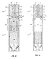
- FIGS. 9A-9C show cross-sectional side views of subsystems of an ESP cooling system in accordance with certain example embodiments.
- FIG. 10 shows a cross-sectional top view of a motor of an ESP cooling system in accordance with certain example embodiments.
- the terms “a,” “an,” and “the” include both the singular and plural forms of the element(s) they refer to unless the context clearly dictates otherwise. Additionally, the term “includes” means “comprises.” Further, the term “coupled” generally means electrically, electromagnetically, and/or physically (e.g., mechanically or chemically) coupled or linked and does not exclude the presence of intermediate elements between the coupled or associated items absent specific contrary language. Although water/steam is described in certain embodiments, it should be understood that any working fluid with suitable characteristics for a particular application can be used with the cooling devices described herein (e.g., a refrigerator).
- Cooling devices for Electric Submersible Pumps are described herein. As described in more detail below, these cooling devices can remove all or at least a portion of the heat load from an ESP motor to lower the internal temperature of the motor and improve its reliability.
- FIGS. 1A and 1B illustrate views of a cooling device 10 , with FIG. 1B being a cross-sectional view of FIG. 1A .
- cooling device 10 is not drawn to scale in the figures.
- the evaporator and condenser sections (e.g., heat exchanger system 18 shown in FIG. 1B ) of cooling device 10 have been significantly shortened relative to other features to allow for easier viewing.
- the condenser can be physically separated from the evaporator.
- cooling device 10 can be between about 4 and 8 inches in diameter and between 10 and 50 feet long. In a particular embodiment, cooling device 10 can be between about 5.5 and 6.5 inches in diameter and between about 20 and 40 feet long, or more preferably between about 25 and 35 feet long, such as about 6 inches and about 30 feet long.
- the ratio of the length to diameter of cooling devices described herein is at least 15:1 (e.g., 8 inches and 10 feet long), and in some embodiments, at least 30:1 (e.g., 8 inches and 20 feet long).
- cooling unit 10 can be formed to have a plurality of housings that cover, contain, and/or otherwise protect internal areas of cooling unit 10 .
- a compressor housing 12 can cover or contain a compressor system 14 .
- a second housing such as finned housing 16
- Housings 12 and 16 can be coupled together, such as by weld joint 20 .
- a first end 22 of cooling device 10 can be configured to be coupled to an ESP system, and the second end can have an end cap 24 .
- Cooling device 10 can comprise a refrigerator system (e.g., a system that has a compressor, condenser, evaporator, and pressure reduction device) that can be bolted to the end of the ESP motor (not shown) near compressor system 14 .
- cooling device 10 can be bolted to the ESP motor using a standard flange.
- the refrigerator system can be sized and configured in such a way as to accommodate an expansion and contraction of the working fluid, even when mixed with the lubricant of the refrigerator system.
- the refrigeration system (or any other portion of the cooling device 10 that requires power) can receive power from any of a number of power sources. Examples of a power source can include, but are not limited to, a battery, the motor (as defined below with respect to FIGS. 9A-10 ), and a generator at the surface (provided by a power transmission device, such as a cable).
- compressor system 14 can be driven by a magnetic coupling 26 .
- a female side 28 of magnetic coupling 26 (shown in at the top of FIG. 2 ) can be driven by the existing motor shaft of the ESP system using a standard spline coupling.
- a male side 30 of the magnetic coupling 26 can be configured to drive a shaft of compressor system 14 .
- a metal plate 32 (e.g., a stainless steel plate).
- Plate 32 can be machined directly from compressor housing 12 . As shown in FIG. 5 , plate 32 can be positioned between the two sections of magnetic coupling 26 , thereby acting as a pressure boundary between a working fluid (e.g., steam) and an internal motor lubricating fluid (e.g., oil). In this manner, plate 32 forms a portion of the hermetic seal between the working fluid (e.g., steam) and the internal motor oil.
- a working fluid e.g., steam
- an internal motor lubricating fluid e.g., oil
- all surfaces separating the working fluid (e.g., steam) and oil are made with welded connections, thereby preventing the working fluid (e.g., steam) steam from contaminating the internal motor oil.
- the working fluid e.g., steam
- the following embodiments describe the working fluid as water/steam; however, it should be understood that, depending on the particular conditions of operation, other suitable working fluids can be used in combination with the cooling devices described herein.
- water/steam can be well-suited for operation at temperatures, for example, of about 150-250 degrees Celsius, but other working fluids could be more desirable if the cooling device is to be used at temperatures outside of this range.
- Magnetic coupling 26 can be based on a design available through MMC Enterprises Corporation, however any suitable coupling may be used.
- the coupling can be sized for the torque requirements of compressor system 14 .
- coupling 26 can be selected so that it will function at 3600 rpm and at a working temperature of up to 280° C.
- steam inlet 34 and steam outlet 36 are provided for receiving and delivering a refrigerator working fluid (also called, more simply, working fluid) that can include, but is not limited to, water and a lubricant.
- a refrigerator working fluid also called, more simply, working fluid
- These connections to compressor system 14 can be located at the end opposite the drive shaft of the compressor system 14 , as shown in FIG. 2 .
- high temperature steam leaving the compressor outlet 36 can flow over a domed head of a condenser shell 38 and into an annulus 40 between condenser shell 38 and the housing 16 of cooling device 10 .
- heat is rejected from the steam through housing 16 of cooling device 10 to an external product stream that flows past housing 16 .
- the resulting high temperature liquid can collect at an outlet of the condenser shown at the bottom of FIG. 3 .
- the high temperature liquid then flows through a pressure drop in a pressure reduction device 42 .
- the low temperature liquid-vapor mixture at the outlet of pressure reduction device 42 is then routed into the evaporator heat exchanger system 18 .
- the low temperature steam leaving pressure reduction device 42 is routed through the four-pass tube-in-tube evaporator heat exchanger 44 shown in FIG. 4 .
- the steam first flows through a steam supply tube 46 at the center of the evaporator tube bundle along the full length of the evaporator heat exchanger system 18 .
- the steam flows into an annulus 48 between an outer steam tube 50 and a tube 52 carrying the motor oil from the ESP.
- the compressor housing 14 can have one or more passageways 54 (e.g., small axial channels drilled into the housing wall) for oil flow past compressor 14 in each direction.
- a total of 101 ⁇ 4′′ diameter passageways (5 on the oil supply and 5 on the oil return) are incorporated into the housing to allow for a substantial flow cross-sectional area to minimize pressure drop in the oil.
- Oil can be delivered to the evaporator via oil supply passageways 54 to an oil supply manifold 56 and into an oil supply tube 58 .
- oil can return through an oil return tube 60 , to an oil return manifold 62 , and into oil return passageways 54 .
- manifolds 64 (which include oil supply and return manifolds 56 , 62 ) can be provided on either end of compressor 14 to collect the oil from these passageways and to route the oil as necessary. These oil flow passages through the compressor housing 12 allow oil flow from the ESP motor to evaporator heat exchanger system 18 .
- cooling device components described herein were developed with the intent of meeting heat transfer, pressure, and assembly requirements.
- the refrigerator components can be welded together to ensure that the cooling device does not fail in view of the high differential pressure between the product and steam.
- compressor 14 can require most of the internal diameter of the compressor housing 12 which can complicate the oil manifold shown in FIG. 6 .
- the compressor housing 12 (including plate 32 ) can be machined out of a single stainless steel rod, with small bypass holes drilled into compressor housing 12 to allow for oil exchange across housing 12 . If desired, a manifold adapter can be welded into housing 12 to connect the bypass holes after the compressor is installed to provide improved structural strength.
- compressors Based on the requirements of the cooling device, although other compressors may be used, two types of compressors are preferred.
- the two preferred compressor types are rotary vane and swash or wobble plate reciprocating.
- Lubricants which are compatible with steam and capable of withstanding the operating temperatures are preferably used with the cooling device.
- the cooling systems disclosed herein can be easily coupled to existing ESP systems.
- the cooling systems can simply be bolted onto high temperature ESPs.
- a mechanical interface for the refrigerator add-on can be provided, such as a spline coupling to the motor shaft to drive the refrigerator's compressor and lubricating oil circulation pump.
- ESPs in production are already equipped with this type of spline coupling at the end of the motor to allow for the use of multiple motors in series.
- the cooling devices described herein take advantage of current configurations of ESP so that they can be readily coupled to the ESPs as, for example, a bolt-on accessory.
- a bolt-on cooling device e.g., a single stage vapor compression refrigerator with a four component cycle
- the vapor compressor of the refrigerator compresses a working fluid (preferably water) from saturated vapor at a low temperature and pressure to a high pressure superheated vapor.
- the high temperature working fluid can then be directed through a condenser heat exchanger that rejects heat to the reservoir fluids flowing past the motor and refrigerator. Heat rejection from the condenser heat exchanger causes the working fluid to de-superheat and condense to a saturated or slightly subcooled condition at the condenser outlet.
- the working fluid can be any lubricant or refrigerant. In certain example embodiments, the working fluid is effective in heat transfer at temperatures of approximately 200° C., which is a common operating temperature for ESPs.
- the high temperature liquid working fluid can then be directed through a pressure reduction device, which causes a reduction in pressure of the working fluid and a corresponding reduction in temperature.
- the fluid at the exit of the pressure reduction device is a low temperature two-phase liquid-vapor mixture.
- This low temperature two-phase mixture can then be routed through an evaporator heat exchanger, where heat can be accepted from a higher temperature heat source such as the internal lubricating oil of the ESP motor that is in contact with the heat generating components of the motor. Heat transfer from the heat source to the working fluid in the evaporator causes the working fluid to evaporate.
- the fluid leaving the evaporator heat exchanger is a saturated or slightly superheated low temperature vapor that then re-enters the compressor to begin another cycle.
- the evaporator heat exchanger can use a shell and tube heat exchanger with the refrigerant on the tube side and the motor's lubricating oil on the shell side.
- an internal lubricating oil pump can be included on the shell side to circulate the oil axially between the motor and the refrigerator.
- the condenser heat exchanger can be a falling film design that would give the working fluid a surface to condense; the outside of the condensing surface being cooled by the reservoir fluids flowing axially past the motor housing.
- the pressure reduction device can be an orifice type expansion device.
- the compressor can bleed power from the main rotating shaft of the motor.
- the compressor (or other portion of the cooling device 10 ) can have a motor that provides power to the compressor. This compressor could be any type of rotary compressor that would fit in the limited diameter of the ESP motor.
- FIG. 7A A finite element structural analysis of the finned refrigerator housing has been performed and the results of the finite element analysis are shown in FIG. 7A .
- maximum stress in the wall of the housing with a 3000 psi external pressure (and 0 psi internal pressure) is calculated as 34 ksi.
- the yield strength of the carbon steel housings is 75 ksi. The stresses generated in the wall of the finned housing are well below the yield strength of the material.
- Compressor housing 12 can be machined from a stainless steel rod with a yield strength of (typically) 45 ksi. The stresses in the compressor housing are again well below the yield strength of the housing material.
- the cooling devices described herein remove heat from internal motor oil to permit the ESP to operate at lower temperatures. By consuming energy directly from the ESP motor to drive the compressor, the cooling devices described herein do not require a separate motor source for operation. At high temperatures in the condenser heat exchanger, the cooling devices can transfer to the product stream a heat load equal to the total heat load absorbed from the motor oil in the evaporator plus the work supplied to the compressor. To determine flow rates, temperatures, pressures, and refrigeration loads, a computer program was developed to calculate all of the state points in the thermodynamic cycle.
- FIG. 8 shows a block diagram of the cycle. It is taken from the EES (Engineering Equation Solver) code that calculates the cycle parameters.
- the variables shown are linked to the code and change as the code parameters are manipulated.
- the key inputs are the steam quality at the compressor inlet (84%), the product water cut (40%) and the product viscosity (90 cp). Units are generally metric.
- the EES program includes not only a calculation of the steam state points at various points in the thermodynamic cycle but also heat transfer calculations for the condenser and evaporator heat exchangers.
- the program calculates the heat transfer capacity (the amount of heat transfer that the heat exchanger is capable of) based on the available heat exchanger area for a refrigerator that will fit in the 30 ft length requirement.
- the heat transfer calculations are for the tube-in-tube evaporator design and the condenser with a finned housing.
- P evap is the refrigeration load that the evaporator heat exchanger can provide while P refrig is what is required to cool the internal motor oil by 40° C.
- the refrigerator sized in FIG. 8 is extracting a considerable portion of the 28 kW total heat generation rate in the baseline ESP motor.
- the compressor must consume 6.3 kW or 8.4 hp.
- the compressor's power consumption was calculated assuming a compressor isentropic efficiency of 66%, which is typical of a reciprocating compressor. This power will be directly extracted from the ESP motor.
- Our baseline motor is a 228 hp motor. Therefore, the refrigerator will consume less than 5% of the total motor output.
- FIGS. 9A-9C show cross-sectional side views of ESP cooling systems in accordance with certain example embodiments.
- FIG. 9A shows a cross-sectional side view of the compressor system 14 of the cooling device 10 and the bottom of the motor 70 of the ESP.
- FIG. 9B shows a cross-sectional side view of the compressor system 14 of the cooling device 10 and the entire motor 70 of the ESP.
- FIG. 9C shows a cross-sectional side view of another compressor system 14 of the cooling device 10 and the bottom of the motor 70 of the ESP.
- the motor 70 is coupled to the cooling device 10 .
- the bottom end of the motor 70 can have a coupling system that couples to a complementary coupling system disposed near the compressor system 14 at the top end of the cooling device 10 .
- the motor 70 can be coupled to the cooling device 10 , directly or indirectly, in one or more of a number of ways.
- the motor 70 and the cooling device 10 can have mating threads disposed thereon to allow the motor 70 and the cooling device 10 to threadably couple to each other.
- the motor 70 and the cooling device 10 can have apertures that can receive one or more coupling devices (e.g., bolts) that are used to couple the motor 70 and the cooling device 10 to each other.
- the manifold 64 also called a cooling device passageway
- the manifold 64 and the passageways 73 can form a sealed coupling with each other when the cooling device 10 and the motor 70 become coupled to each other.
- the passageways 73 can be disposed in various portions of the motor 70 and can be used to circulate working fluid throughout the motor 70 .
- the passageways 73 can be disposed in a cavity 77 of the shaft 76 (also called a shaft passageway).
- the passageways 73 can be disposed in one or more channels 85 in the stator 84 (also called stator passageways).
- the passageway 73 can start at the manifold 64 , travel through a channel 91 to a fluid circulating device 72 (e.g., a pump), flow through a channel 75 disposed toward the bottom of the shaft 76 to the cavity 77 of the shaft 76 , then flow through another channel 86 disposed toward the top of the shaft 76 to a header section 87 at the top of the motor 70 , then through the channels 85 in the stator 84 , and back to the manifold 64 or other part of the cooling device 10 that feeds to the passageways 54 of the cooling device 10 .
- a fluid circulating device 72 e.g., a pump
- the working fluid can flow through the passageways 73 of the motor 70 to absorb heat from the motor and through the passageways 54 of the cooling device 10 to cool the working fluid.
- at least a portion of the working fluid can also flow from the shaft 76 through a gap 97 between the rotor 80 and the stator 84 .
- the passageway 54 of the cooling device 10 and the passageway 73 of the motor 70 can form a substantially closed loop.
- the motor 70 can include one or more of a number of features.
- the motor 70 can include a motor housing 78 that forms a cavity inside of which the motor is disposed.
- the motor housing 78 of the motor 70 can have one or more of a number of shapes when viewed cross-sectionally from above.
- the motor housing 78 can be substantially cylindrical when viewed cross-sectionally from above.
- the motor housing 78 can have a top end 89 and a bottom end 88 .
- the shaft 76 of the motor 70 can be oriented vertically within and between the top end 89 and the bottom end 88 of the motor housing 78 . In such a case, the shaft 76 can be substantially centered within the motor housing 78 along the length (between the top end 89 and the bottom end 88 ) of the motor housing 78 .
- the bottom end of the shaft 76 can be coupled to a drive system (e.g., coupling system 26 ) of the cooling device 10 .
- a drive system e.g., coupling system 26
- the shaft 76 causes a portion of the drive system of the cooling device 10 to rotate, which provides energy to operate one or more components (e.g., the compressor system 14 ) of the cooling device 10 .
- the drive system of the cooling device 10 can be configured to use one or more of a number of technologies.
- the drive system can include a coupling system 26 , as shown in FIG. 2 above, where the top end of the coupling system 26 is driven by the shaft 76 , while the bottom end of the coupling system 26 (disposed at the first end 22 of the cooling device 10 ) drives one or more components (e.g., the compressor system 14 ) of the cooling device 10 .
- the coupling system 26 can be magnetic (as shown in FIGS. 9A and 9B ), fluid-based (as shown in FIG. 9C ), any other technology, or any combination thereof.
- a coupling system 26 is fluid-based, as shown in FIG.
- the coupling system 26 of the drive system can include a torque converter 67 , where the top end of the torque converter 66 is driven by the shaft 76 , while the bottom end of the torque converter 67 (disposed at the first end 22 of the cooling device 10 , in place of the magnetic coupling system 26 shown, for example, in FIGS. 1B, 9A, and 9B ) drives one or more components of the cooling device 10 .
- a fluid coupling system 26 can include one or more clutches 66 (or similar devices) that are coupled to a component (e.g., compressor system 14 , fluid circulating device 72 ) of the cooling device 10 and/or the motor 70 to control the operation (e.g., on, off, increase speed, decrease speed) of such component.
- a component e.g., compressor system 14 , fluid circulating device 72
- the one or more clutches 66 can be disengaged if the compressor system 14 fails so that the compressor system 14 does not bleed power from the motor 70 .
- one or more valves 68 can be disposed in the passageways 73 within the motor 70 and/or the passageways 54 within the cooling device 10 .
- valve 68 can be closed to isolate a portion of a passageway 73 within the motor 70 and/or a passageway 54 within the cooling device 10 .
- Each clutch 66 and/or valve 68 can be controlled automatically or remotely by a user. In some cases, one or more valves 68 can operate automatically if a clutch operates.
- the shaft 76 can be a single, continuous piece or a number of shafts that are coupled to each other end-to-end so that the multiple shafts act in unison as a single shaft. In either case, in addition to the channel 86 disposed toward the top of the shaft 76 , there can be one or more other channels 81 in the shaft 76 that are positioned between the channel 86 disposed toward the top of the shaft 76 and the channel 75 toward the bottom of the shaft 76 .
- a regulator 69 (or similar device) can be used to divert some of the working fluid to go through an additional channel 81 while allowing the remainder of the working fluid to continue up within the cavity 77 of the shaft 76 , eventually flowing to another (e.g., adjacent) stator or another portion of the same stator.
- These additional channels 81 in the shaft 76 can be used to lubricate bearings 82 (or other similar components that assist in the operation of the motor 70 ) and/or to connect to channels 85 in the stator 84 .
- the cavity 77 running within the shafts can be substantially continuous.
- the motor 70 can have a single rotor 80 and stator 84 disposed within the motor housing 78 .
- the motor 70 can have multiple motors, which means that there are multiple rotors 80 and stators 84 disposed within the motor housing 78 .
- the motor 70 can have a single rotor 80 and multiple stators 84 . In such a case, when there are multiple stators 84 , the stators 84 can be coupled to each other or otherwise positioned end-to-end within the motor housing 78 . Regardless of the number of stators 84 , the shaft 76 can be disposed within the approximate center of each stator 84 along the length of the stator 84 , as shown in FIG. 10 .
- a stator 84 can have multiple channels 85 disposed therein. These channels 85 can be aligned with a channel (e.g., channel 86 , channel 81 ) in the shaft 76 and/or with another channel 85 (for example, as from an adjacent stator 84 ).
- a channel e.g., channel 86 , channel 81
- another channel 85 for example, as from an adjacent stator 84 .
- each stator 84 and/or rotor 80 can be removed from the motor housing 70 and replaced by a user. This allows for maintenance and/or replacement of a stator 84 and/or a rotor 80 without having to replace the entire motor 70 .
- the motor 70 can be cooled.
- working fluid can be received from the cooling device 10 at a first temperature in at least one passageway 73 disposed in a bottom end 88 of the motor 70 .
- the working fluid can be circulated through the passageways 73 disposed in another portion of the motor 70 .
- heat transfers from the motor 70 to the working fluid which causes the working fluid to be at a second, higher temperature relative to the first temperature.
- the working fluid is sent back to the cooling device 10 .
- the process can then be repeated, and in many cases, the process is continuous for some period of time. For example, while the compressor system 14 of the cooling device 10 is operating, the process is continuous.
- one or more sensors can be used in the cooling device 10 and/or the motor 70 to help determine whether some or all of the components of the cooling device 10 and/or the motor 70 are operating properly.
- sensors can measure any of a number of factors, including but not limited to the flow rate of the working fluid, the pressure of the working fluid within a passageway, the temperature of a stator 85 , and an amount of power consumed by the compressor system 14 .
Landscapes
- Engineering & Computer Science (AREA)
- Mechanical Engineering (AREA)
- General Engineering & Computer Science (AREA)
- Physics & Mathematics (AREA)
- Thermal Sciences (AREA)
- Mining & Mineral Resources (AREA)
- Structures Of Non-Positive Displacement Pumps (AREA)
- Motor Or Generator Cooling System (AREA)
Abstract
Description
Claims (15)
Priority Applications (1)
| Application Number | Priority Date | Filing Date | Title |
|---|---|---|---|
| US14/577,926 US9797402B2 (en) | 2011-10-18 | 2014-12-19 | Cooling devices and methods for use with electric submersible pumps |
Applications Claiming Priority (4)
| Application Number | Priority Date | Filing Date | Title |
|---|---|---|---|
| US201161548353P | 2011-10-18 | 2011-10-18 | |
| US13/655,328 US8899054B2 (en) | 2011-10-18 | 2012-10-18 | Cooling devices and methods for use with electric submersible pumps |
| US14/540,882 US9394917B2 (en) | 2011-10-18 | 2014-11-13 | Cooling devices and methods for use with electric submersible pumps |
| US14/577,926 US9797402B2 (en) | 2011-10-18 | 2014-12-19 | Cooling devices and methods for use with electric submersible pumps |
Related Parent Applications (1)
| Application Number | Title | Priority Date | Filing Date |
|---|---|---|---|
| US14/540,882 Continuation-In-Part US9394917B2 (en) | 2011-10-18 | 2014-11-13 | Cooling devices and methods for use with electric submersible pumps |
Publications (2)
| Publication Number | Publication Date |
|---|---|
| US20150139822A1 US20150139822A1 (en) | 2015-05-21 |
| US9797402B2 true US9797402B2 (en) | 2017-10-24 |
Family
ID=53173497
Family Applications (1)
| Application Number | Title | Priority Date | Filing Date |
|---|---|---|---|
| US14/577,926 Active 2033-11-07 US9797402B2 (en) | 2011-10-18 | 2014-12-19 | Cooling devices and methods for use with electric submersible pumps |
Country Status (1)
| Country | Link |
|---|---|
| US (1) | US9797402B2 (en) |
Cited By (3)
| Publication number | Priority date | Publication date | Assignee | Title |
|---|---|---|---|---|
| US11808268B2 (en) | 2020-10-19 | 2023-11-07 | Milwaukee Electric Tool Corporation | Stick pump assembly |
| US11916451B2 (en) | 2020-04-08 | 2024-02-27 | Halliburton Energy Services, Inc. | Axial flux submersible electric motor |
| US12523131B2 (en) | 2024-06-25 | 2026-01-13 | Halliburton Energy Services, Inc. | Electric submersible pump with active cooling |
Families Citing this family (2)
| Publication number | Priority date | Publication date | Assignee | Title |
|---|---|---|---|---|
| CN107438716B (en) * | 2016-09-21 | 2019-12-27 | 易达科技(深圳)有限公司 | Submersible pump system and submersible pump thereof |
| US12378853B2 (en) | 2023-04-20 | 2025-08-05 | Protex ESP, LLC | Safety brake for electrical submersible pumps powered by permanent magnet motors |
Citations (20)
| Publication number | Priority date | Publication date | Assignee | Title |
|---|---|---|---|---|
| US1947630A (en) | 1930-11-28 | 1934-02-20 | Wernert Karl | Submersible pump |
| US2244255A (en) | 1939-01-18 | 1941-06-03 | Electrical Treating Company | Well clearing system |
| US2503456A (en) | 1945-10-25 | 1950-04-11 | Muncie Gear Works Inc | Heat pump |
| US3443641A (en) | 1967-02-27 | 1969-05-13 | William P Mccomb | Method and apparatus for recovery of liquids from a well bore |
| US4610793A (en) | 1983-10-08 | 1986-09-09 | Miller David P J | Oil extraction method |
| US4704823A (en) * | 1984-08-29 | 1987-11-10 | Acrometal Products, Inc. | Abrasive surfacing machine |
| US5477703A (en) | 1994-04-04 | 1995-12-26 | Hanchar; Peter | Geothermal cell and recovery system |
| US5609478A (en) * | 1995-11-06 | 1997-03-11 | Alliance Compressors | Radial compliance mechanism for corotating scroll apparatus |
| US5694780A (en) | 1995-12-01 | 1997-12-09 | Alsenz; Richard H. | Condensed liquid pump for compressor body cooling |
| US6561775B1 (en) | 2001-05-21 | 2003-05-13 | Wood Group Esp, Inc. | In situ separable electric submersible pump assembly with latch device |
| US20030132003A1 (en) | 2001-12-21 | 2003-07-17 | Arauz Grigory L. | Sealed ESP motor system |
| US20040112601A1 (en) * | 2002-12-11 | 2004-06-17 | Jean-Michel Hache | Apparatus and method for actively cooling instrumentation in a high temperature environment |
| US20040256109A1 (en) | 2001-10-09 | 2004-12-23 | Johnson Kenneth G | Downhole well pump |
| US20090151928A1 (en) * | 2007-12-17 | 2009-06-18 | Peter Francis Lawson | Electrical submersible pump and gas compressor |
| US20090272129A1 (en) | 2008-04-30 | 2009-11-05 | Altarock Energy, Inc. | Method and cooling system for electric submersible pumps/motors for use in geothermal wells |
| US20100026108A1 (en) * | 2006-06-19 | 2010-02-04 | Thermal Motor Innovations, Llc | Electric motor with heat pipes |
| US7661460B1 (en) | 2003-12-18 | 2010-02-16 | Advanced Thermal Sciences Corp. | Heat exchangers for fluid media |
| US20100115978A1 (en) | 2007-04-18 | 2010-05-13 | Pavel Simka | Heat pump system and method for pumping liquids |
| US20110211979A1 (en) * | 2010-02-26 | 2011-09-01 | Behrend Goswin Schlenhoff | Cooling system for a multistage electric motor |
| US20120156079A1 (en) * | 2010-12-15 | 2012-06-21 | Kabushiki Kaisha Kobe Seiko Sho (Kobe Steel, Ltd.) | Screw compressor |
-
2014
- 2014-12-19 US US14/577,926 patent/US9797402B2/en active Active
Patent Citations (22)
| Publication number | Priority date | Publication date | Assignee | Title |
|---|---|---|---|---|
| US1947630A (en) | 1930-11-28 | 1934-02-20 | Wernert Karl | Submersible pump |
| US2244255A (en) | 1939-01-18 | 1941-06-03 | Electrical Treating Company | Well clearing system |
| US2503456A (en) | 1945-10-25 | 1950-04-11 | Muncie Gear Works Inc | Heat pump |
| US3443641A (en) | 1967-02-27 | 1969-05-13 | William P Mccomb | Method and apparatus for recovery of liquids from a well bore |
| US4610793A (en) | 1983-10-08 | 1986-09-09 | Miller David P J | Oil extraction method |
| US4704823A (en) * | 1984-08-29 | 1987-11-10 | Acrometal Products, Inc. | Abrasive surfacing machine |
| US5477703A (en) | 1994-04-04 | 1995-12-26 | Hanchar; Peter | Geothermal cell and recovery system |
| US5609478A (en) * | 1995-11-06 | 1997-03-11 | Alliance Compressors | Radial compliance mechanism for corotating scroll apparatus |
| US5694780A (en) | 1995-12-01 | 1997-12-09 | Alsenz; Richard H. | Condensed liquid pump for compressor body cooling |
| US6561775B1 (en) | 2001-05-21 | 2003-05-13 | Wood Group Esp, Inc. | In situ separable electric submersible pump assembly with latch device |
| US20040256109A1 (en) | 2001-10-09 | 2004-12-23 | Johnson Kenneth G | Downhole well pump |
| US20030132003A1 (en) | 2001-12-21 | 2003-07-17 | Arauz Grigory L. | Sealed ESP motor system |
| US20050089419A1 (en) * | 2001-12-21 | 2005-04-28 | Schlumberger Technology Corporation | Sealed ESP Motor System |
| US6769487B2 (en) | 2002-12-11 | 2004-08-03 | Schlumberger Technology Corporation | Apparatus and method for actively cooling instrumentation in a high temperature environment |
| US20040112601A1 (en) * | 2002-12-11 | 2004-06-17 | Jean-Michel Hache | Apparatus and method for actively cooling instrumentation in a high temperature environment |
| US7661460B1 (en) | 2003-12-18 | 2010-02-16 | Advanced Thermal Sciences Corp. | Heat exchangers for fluid media |
| US20100026108A1 (en) * | 2006-06-19 | 2010-02-04 | Thermal Motor Innovations, Llc | Electric motor with heat pipes |
| US20100115978A1 (en) | 2007-04-18 | 2010-05-13 | Pavel Simka | Heat pump system and method for pumping liquids |
| US20090151928A1 (en) * | 2007-12-17 | 2009-06-18 | Peter Francis Lawson | Electrical submersible pump and gas compressor |
| US20090272129A1 (en) | 2008-04-30 | 2009-11-05 | Altarock Energy, Inc. | Method and cooling system for electric submersible pumps/motors for use in geothermal wells |
| US20110211979A1 (en) * | 2010-02-26 | 2011-09-01 | Behrend Goswin Schlenhoff | Cooling system for a multistage electric motor |
| US20120156079A1 (en) * | 2010-12-15 | 2012-06-21 | Kabushiki Kaisha Kobe Seiko Sho (Kobe Steel, Ltd.) | Screw compressor |
Non-Patent Citations (2)
| Title |
|---|
| International Search Report from Corresponding PCT Application No. PCT/US2012/60877 dated Jan. 11, 2013. |
| Written Opinion of the International Search Authority from corresponding PCT Application No. PCT/US2012/60877 dated Jan. 11, 2013. |
Cited By (5)
| Publication number | Priority date | Publication date | Assignee | Title |
|---|---|---|---|---|
| US11916451B2 (en) | 2020-04-08 | 2024-02-27 | Halliburton Energy Services, Inc. | Axial flux submersible electric motor |
| US11916450B2 (en) | 2020-04-08 | 2024-02-27 | Halliburton Energy Services, Inc. | Axial flux submersible electric motor |
| US11808268B2 (en) | 2020-10-19 | 2023-11-07 | Milwaukee Electric Tool Corporation | Stick pump assembly |
| US12163524B2 (en) | 2020-10-19 | 2024-12-10 | Milwaukee Electric Tool Corporation | Stick pump assembly |
| US12523131B2 (en) | 2024-06-25 | 2026-01-13 | Halliburton Energy Services, Inc. | Electric submersible pump with active cooling |
Also Published As
| Publication number | Publication date |
|---|---|
| US20150139822A1 (en) | 2015-05-21 |
Similar Documents
| Publication | Publication Date | Title |
|---|---|---|
| US9394917B2 (en) | Cooling devices and methods for use with electric submersible pumps | |
| US9797402B2 (en) | Cooling devices and methods for use with electric submersible pumps | |
| US10358908B2 (en) | Tool and method for actively cooling downhole electronics | |
| RU2686971C2 (en) | Optimised cooling of electric motor in pump compressor formation | |
| US6769487B2 (en) | Apparatus and method for actively cooling instrumentation in a high temperature environment | |
| AU2014260530B2 (en) | A thermodynamic machine | |
| US20110138809A1 (en) | Operating a sub-sea organic rankine cycle (orc) system using individual pressure vessels | |
| CA3139222C (en) | Active and passive refrigeration systems for downhole motors | |
| US12305467B2 (en) | Spool-type pitless adapter for groundwater heat exchanger | |
| CN109653708A (en) | A kind of device of the component of the cooling downhole tool based on steam compression cycle | |
| CA2654339C (en) | Heat engine apparatus and method | |
| CA2960471C (en) | Refrigeration system with internal oil circulation | |
| US20160290363A1 (en) | Compression Apparatus | |
| US20260103963A1 (en) | In-Line Fluid System with In-Line Fluid End | |
| CN223036663U (en) | A pumpless ultra-long gravity heat pipe refrigeration system for deep mines | |
| US12385673B1 (en) | High temperature industrial heat pump with novel method to make use of shallow low-GradeGeothermal energy | |
| WO2026085123A1 (en) | In-line fluid system with pressurized coupling | |
| WO2026085115A1 (en) | In-line fluid system with in-line fluid end | |
| WO2026085132A1 (en) | Using multiple in-line fluid systems | |
| WO2026085118A1 (en) | In-line fluid system | |
| WO2026085154A1 (en) | In-line sealed electric motor for pipelines | |
| CN121631650A (en) | Pump-free driving ultra-long gravity heat pipe type refrigerating system applied to deep mine | |
| JP2014227995A (en) | Geothermal power generation method and device |
Legal Events
| Date | Code | Title | Description |
|---|---|---|---|
| AS | Assignment |
Owner name: CHEVRON, U.S.A. INC., CALIFORNIA Free format text: ASSIGNMENT OF ASSIGNORS INTEREST;ASSIGNOR:GAMBOA, JOSE A.;REEL/FRAME:035816/0855 Effective date: 20141219 Owner name: LOS ALAMOS NATIONAL SECURITY, LLC., NEW MEXICO Free format text: ASSIGNMENT OF ASSIGNORS INTEREST;ASSIGNOR:JANKOWSKI, TODD ANDREW;REEL/FRAME:035816/0677 Effective date: 20141219 |
|
| AS | Assignment |
Owner name: U.S. DEPARTMENT OF ENERGY, DISTRICT OF COLUMBIA Free format text: CONFIRMATORY LICENSE;ASSIGNOR:LOS ALAMOS NATIONAL SECURITY;REEL/FRAME:040867/0972 Effective date: 20161228 |
|
| AS | Assignment |
Owner name: LOS ALAMOS NATIONAL SECURITY, LLC, NEW MEXICO Free format text: CORRECTIVE ASSIGNMENT TO CORRECT THE RECEIVING PARTY NAME PREVIOUSLY RECORDED ON REEL 035816 FRAME 0677. ASSIGNOR(S) HEREBY CONFIRMS THE ASSIGNMENT;ASSIGNOR:JANKOWSKI, TODD ANDREW;REEL/FRAME:043924/0636 Effective date: 20141219 Owner name: CHEVRON U.S.A. INC., CALIFORNIA Free format text: CORRECTIVE ASSIGNMENT TO CORRECT THE ASSIGNEE NAME PREVIOUSLY RECORDED AT REEL: 035816 FRAME: 0855. ASSIGNOR(S) HEREBY CONFIRMS THE ASSIGNMENT;ASSIGNOR:GAMBOA, JOSE A.;REEL/FRAME:043921/0588 Effective date: 20141219 |
|
| STCF | Information on status: patent grant |
Free format text: PATENTED CASE |
|
| AS | Assignment |
Owner name: TRIAD NATIONAL SECURITY, LLC, NEW MEXICO Free format text: ASSIGNMENT OF ASSIGNORS INTEREST;ASSIGNOR:LOS ALAMOS NATIONAL SECURITY, LLC;REEL/FRAME:047485/0103 Effective date: 20181101 |
|
| MAFP | Maintenance fee payment |
Free format text: PAYMENT OF MAINTENANCE FEE, 4TH YEAR, LARGE ENTITY (ORIGINAL EVENT CODE: M1551); ENTITY STATUS OF PATENT OWNER: LARGE ENTITY Year of fee payment: 4 |
|
| MAFP | Maintenance fee payment |
Free format text: PAYMENT OF MAINTENANCE FEE, 8TH YEAR, LARGE ENTITY (ORIGINAL EVENT CODE: M1552); ENTITY STATUS OF PATENT OWNER: LARGE ENTITY Year of fee payment: 8 |