US979719A - Grate. - Google Patents
Grate. Download PDFInfo
- Publication number
- US979719A US979719A US43467208A US1908434672A US979719A US 979719 A US979719 A US 979719A US 43467208 A US43467208 A US 43467208A US 1908434672 A US1908434672 A US 1908434672A US 979719 A US979719 A US 979719A
- Authority
- US
- United States
- Prior art keywords
- basket
- frame
- crown
- grate
- pivots
- Prior art date
- Legal status (The legal status is an assumption and is not a legal conclusion. Google has not performed a legal analysis and makes no representation as to the accuracy of the status listed.)
- Expired - Lifetime
Links
- 239000002956 ash Substances 0.000 description 2
- 235000002918 Fraxinus excelsior Nutrition 0.000 description 1
- 238000010276 construction Methods 0.000 description 1
- 230000000694 effects Effects 0.000 description 1
- 230000037431 insertion Effects 0.000 description 1
- 238000003780 insertion Methods 0.000 description 1
- 230000000284 resting effect Effects 0.000 description 1
Images

Classifications
-
- F—MECHANICAL ENGINEERING; LIGHTING; HEATING; WEAPONS; BLASTING
- F24—HEATING; RANGES; VENTILATING
- F24B—DOMESTIC STOVES OR RANGES FOR SOLID FUELS; IMPLEMENTS FOR USE IN CONNECTION WITH STOVES OR RANGES
- F24B1/00—Stoves or ranges
- F24B1/18—Stoves with open fires, e.g. fireplaces
- F24B1/191—Component parts; Accessories
- F24B1/193—Grates; Irons
Definitions
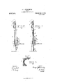
- Figure 1 is a front view of a grate embodying the invention.
- Fig. 2 is a vertical sectional view on line 22 of Fig. 1.
- Fig. 3 is a side view of a portion of the frame, showing the bearing brackets and bearing lugs.
- Fig. 4 is an end view of the basket.
- Fig. 5 is an end view of the crown.
- Fig. 6 is a horizontal section on line 66 of Fig. 3.
- Fig. 7 is a sectional view similar to Fig. 2, but with the crown turned up and back against the basket and with the summer front in place.
- each frame side is provided with a pivot bearing bracket 4 which extends rearwardly from the frame side and also laterally toward the middle of the space between the two frame sides 2.
- the bracket 4 has a pivot bearing 5 to be engaged by the pivot or trunnion of the basket, and a stop shoulder or surface 6 to be engaged by a portion of the basket when the latter is dumped forward and also to be engaged by the crown when the latter is tilted upward and backward.
- Each frame side is also provided with a pivot bearing lug 7 situated below the bracket 4, extending a little backward from the side 2 and also laterally inward to be in the path of a portion of the lower part of the basket so as to arrest the latter in its normal position.
- gage the lower part of the summer front or to engage the lower part of the crown when the same is in normal position.
- the basket 10 is the basket, which is narrower than the space between the sides 2 so as to be readily inserted between them and so as to be tilted forward between the sides to dump the contents of the basket. It is provided with pivots or trunnions 11 arranged to fit in the bearings 5 of the brackets 4, and with laterally extending steps 12 which engage the backs of the lugs 7 to sustain the basket in its vertical or normal position.
- 13 is a space or notch in the front 14 of the basket which enables the front to swing over the bracket 4, and 15 is a stop on the front which engages the shoulder 6 when the basket has been tilted forward into dumping position.
- the parts are so pro portioned that the basket will remain by its own weight in this position resting against the shoulders 6.
- the crown 17 is the crown arranged between the sides 2 and below and a little forward of the front 14 of the basket. It is provided with pivots or trunnions 18 which fit in the bearings of the lugs 7, so that the crown may be tilted forward and upward on a horizontal axis against the shoulders 6.
- the crown in its normal position occupies the space between the lower parts of the frame sides 2 which is to be occupied by the lower part of the summer front when the latter is fitted in the frame.
- the pivots 18 are, however, arranged out of the vertical plane of the front and to the rear of the same, as shown, so that when the crown is swung up against the shoulders 6 it will be to the rear of the plane of the summer front and permit the insertion of the latter.
- the front 14 of the basket is arranged sufficiently to the rear of the crown to admit of this fitting of the parts.
- the summer front 19 is the summer front which preferably fills the entire space between the frame parts 2, 2 and 3 so as to cover the basket and crown, the latter having been swung up as described.
- the top of the front 19 fits under and within the frame top 3 to hold the front from tipping forward, and it is supported from behind by the stops 8 and 9.
- brackets, lugs and pivots or trunnions are shown as cast integral with the frame, basket and crown, respectively, but it will be understood that they may be attached by rivets, bolts or other means.
- the frame may be set in a masonry fireplace in a permanent manner, or it may have side, rear and top walls which inclose the basket in a known manner.
- hat is claimed is 1.
- a grate the combination of a frame, a basket pivotally mounted therein on a horizontal axis and arranged to be tilted forward between the sides of the frame, a crown pivotally mounted in the frame on a horizontal axis which is at the rear of the crown and at 'a point in advance of the basket, and arranged to be tilted up and back against the front of the basket out of the vertical plane of and to the rear of a summer front, thereby leaving room for a summer front, and a summer front fitting in the frame and occupying by its lower end the space normally occupied by the crown, substantially as set forth.
- a grate the combination of a frame having at each side a pivot bearing, and having below the same a laterally extending bearing lug, a basket having at each side a pivot engaging one of the said p ivot bearings and arranged to be dumped forward, and having stop portions engaging the rear sides of the said bearing lugs to hold the basket in normal position, and a crown below the basket having pivots engaging the said bearing lugs and arranged to be tilted up at the front of the basket, substantially as set forth.
- a grate the combination of a frame, a basket pivotally mounted therein on a horizontal axis and arranged to be tilted forward between the sides of the frame, and a crown arranged tooccupy the space between the sides of the frame below the basket and having rearward extensions carrying pivots 18 which are at the rear of and out of the vertical plane of the crown, and bearings 7 on the frame at the front of the basket and engaging the said pivots, the crown bein adapted to be tilted up against the front or the basket, substantially as set forth.
Landscapes
- Engineering & Computer Science (AREA)
- Chemical & Material Sciences (AREA)
- Combustion & Propulsion (AREA)
- Mechanical Engineering (AREA)
- General Engineering & Computer Science (AREA)
- Toys (AREA)
Description
H. c STUGKENBURG.
' GRATE.
APPLICATION FILED MAY 23, 1908.
:QSCDGGSGS 979,371.95 Patented Dc.27,1910. l jiEE'IW-BHIHG'I 1.-
ATTORNEY H. G. STUOKENBURG.
, GBATE.
APPLIUATION FILED nu 23,1908.
Patented Dec.27,1910.
WITNESSES:
A TTOHNE V THE NORRIS PITIR: cm, IA-"lmuran, n. c
UN 11TH?) %TATE% PATENT FFfE HENRY C. STUCKENBURG, OF LOUISVILLE, KENTUCKY, ASSIGNOR TO BRIDGEFOBD AND COMPANY, OF LOUISVILLE, KENTUCKY, A CORPORATION.
GRATE.
To all whom it may concern:
Be it known that I, T'IENRY G. STUoKnN- mine, a citizen of the United States, residing at Louisville, in the county of Jefferson and State of Kentucky, have invented certain new and useful Improvements in Grates, of which the following is a specification.
In order to make the invention more clearly understood I have shown in the accompanying drawings means for carrying it into practical effect, without limiting my improvements, in their useful applications, to the particular details of construction which, for the sake of example, I have illus trated.
In said drawingsFigure 1 is a front view of a grate embodying the invention. Fig. 2 is a vertical sectional view on line 22 of Fig. 1. Fig. 3 is a side view of a portion of the frame, showing the bearing brackets and bearing lugs. Fig. 4 is an end view of the basket. Fig. 5 is an end view of the crown. Fig. 6 is a horizontal section on line 66 of Fig. 3. Fig. 7 is a sectional view similar to Fig. 2, but with the crown turned up and back against the basket and with the summer front in place.
Referring to the drawings, 1 indicates the frame adapted to be arranged at the front of a fireplace. This frame is or may be of an ornamental character, having sides 2 and a top 3 connecting the sides. The parts 2, 2 and 3 are shown as cast in one piece, but they may be made separate and secured together by rivets or bolts. Each frame side is provided with a pivot bearing bracket 4 which extends rearwardly from the frame side and also laterally toward the middle of the space between the two frame sides 2. The bracket 4 has a pivot bearing 5 to be engaged by the pivot or trunnion of the basket, and a stop shoulder or surface 6 to be engaged by a portion of the basket when the latter is dumped forward and also to be engaged by the crown when the latter is tilted upward and backward. Each frame side is also provided with a pivot bearing lug 7 situated below the bracket 4, extending a little backward from the side 2 and also laterally inward to be in the path of a portion of the lower part of the basket so as to arrest the latter in its normal position.
8 indicates stops to engage the upper part of the summer front when the latter is fitted into the frame, and 9 indicates stops to en- Specification of Letters Patent.
Application filed. May 23, 1908.
Patented Dec. 27, 1916. Serial No. 434,672.
gage the lower part of the summer front, or to engage the lower part of the crown when the same is in normal position.
10 is the basket, which is narrower than the space between the sides 2 so as to be readily inserted between them and so as to be tilted forward between the sides to dump the contents of the basket. It is provided with pivots or trunnions 11 arranged to fit in the bearings 5 of the brackets 4, and with laterally extending steps 12 which engage the backs of the lugs 7 to sustain the basket in its vertical or normal position.
13 is a space or notch in the front 14 of the basket which enables the front to swing over the bracket 4, and 15 is a stop on the front which engages the shoulder 6 when the basket has been tilted forward into dumping position. The parts are so pro portioned that the basket will remain by its own weight in this position resting against the shoulders 6.
16 is a space or notch in the front 14 which enables the lower part of the front to swing backward clear of the bracket 4.
17 is the crown arranged between the sides 2 and below and a little forward of the front 14 of the basket. It is provided with pivots or trunnions 18 which fit in the bearings of the lugs 7, so that the crown may be tilted forward and upward on a horizontal axis against the shoulders 6. The crown in its normal position occupies the space between the lower parts of the frame sides 2 which is to be occupied by the lower part of the summer front when the latter is fitted in the frame. The pivots 18 are, however, arranged out of the vertical plane of the front and to the rear of the same, as shown, so that when the crown is swung up against the shoulders 6 it will be to the rear of the plane of the summer front and permit the insertion of the latter. The front 14 of the basket is arranged sufficiently to the rear of the crown to admit of this fitting of the parts.
19 is the summer front which preferably fills the entire space between the frame parts 2, 2 and 3 so as to cover the basket and crown, the latter having been swung up as described. The top of the front 19 fits under and within the frame top 3 to hold the front from tipping forward, and it is supported from behind by the stops 8 and 9.
The brackets, lugs and pivots or trunnions are shown as cast integral with the frame, basket and crown, respectively, but it will be understood that they may be attached by rivets, bolts or other means.
The frame may be set in a masonry fireplace in a permanent manner, or it may have side, rear and top walls which inclose the basket in a known manner.
It will be understood that by tilting the basket forward, as described, the contents of the basket may be dumped into an ash receptacle, placed for the purpose, in a very convenient manner. Also, that the crown may be swung upward and will so remain, without removing it from the frame, to admit of clearing the ashes from below the basket.
hat is claimed is 1. In a grate the combination of a frame, a basket pivotally mounted therein on a horizontal axis and arranged to be tilted forward between the sides of the frame, a crown pivotally mounted in the frame on a horizontal axis which is at the rear of the crown and at 'a point in advance of the basket, and arranged to be tilted up and back against the front of the basket out of the vertical plane of and to the rear of a summer front, thereby leaving room for a summer front, and a summer front fitting in the frame and occupying by its lower end the space normally occupied by the crown, substantially as set forth.
2. In a grate the combination of a frame having at each side a pivot bearing, and having below the same a laterally extending bearing lug, a basket having at each side a pivot engaging one of the said p ivot bearings and arranged to be dumped forward, and having stop portions engaging the rear sides of the said bearing lugs to hold the basket in normal position, and a crown below the basket having pivots engaging the said bearing lugs and arranged to be tilted up at the front of the basket, substantially as set forth.
3. In a grate the combination of a frame, a basket pivotally mounted therein on a horizontal axis and arranged to be tilted forward between the sides of the frame, and a crown arranged tooccupy the space between the sides of the frame below the basket and having rearward extensions carrying pivots 18 which are at the rear of and out of the vertical plane of the crown, and bearings 7 on the frame at the front of the basket and engaging the said pivots, the crown bein adapted to be tilted up against the front or the basket, substantially as set forth.
I. In a grate the combination of a frame, pivot lugs 4L thereon, and a basket having pivots 11 near the front plane of the hasket and held in bearings in the said lugs, and having stops 15 above the pivots arranged to swing forward and downward in,
front of the pivots and to engage the front of the lugs when the basket is tilted forward of the frame, substantially as set forth.
In testimony whereof I aflix my signature in presence of two witnesses.
HENRY C. STUCKENBURG.
lVitnesses S. P. GAlLBNEATH, J. C. Barns.
Priority Applications (1)
| Application Number | Priority Date | Filing Date | Title |
|---|---|---|---|
| US43467208A US979719A (en) | 1908-05-23 | 1908-05-23 | Grate. |
Applications Claiming Priority (1)
| Application Number | Priority Date | Filing Date | Title |
|---|---|---|---|
| US43467208A US979719A (en) | 1908-05-23 | 1908-05-23 | Grate. |
Publications (1)
| Publication Number | Publication Date |
|---|---|
| US979719A true US979719A (en) | 1910-12-27 |
Family
ID=3048093
Family Applications (1)
| Application Number | Title | Priority Date | Filing Date |
|---|---|---|---|
| US43467208A Expired - Lifetime US979719A (en) | 1908-05-23 | 1908-05-23 | Grate. |
Country Status (1)
| Country | Link |
|---|---|
| US (1) | US979719A (en) |
-
1908
- 1908-05-23 US US43467208A patent/US979719A/en not_active Expired - Lifetime
Similar Documents
| Publication | Publication Date | Title |
|---|---|---|
| US979719A (en) | Grate. | |
| US909756A (en) | Grate. | |
| US167426A (en) | Improvement in fire-place grates | |
| US937685A (en) | Self-dumping grate. | |
| US92906A (en) | Self and william resor | |
| US156762A (en) | Improvement in fire-pots and grates for coal-stoves | |
| US1261068A (en) | Coal-grate. | |
| US528610A (en) | And john zipp | |
| US176439A (en) | Improvement in grates | |
| USRE9252E (en) | perry | |
| US221556A (en) | Improvement in stove-grates | |
| US362265A (en) | Willtam e | |
| US182349A (en) | Improvement in open fire-place grates | |
| US1078769A (en) | Grate. | |
| US422355A (en) | George a | |
| US1038987A (en) | Locomotive ash-pan. | |
| US147347A (en) | Improvement in combined grates and ash-sifters | |
| US884615A (en) | Grate for open fireplaces. | |
| US178171A (en) | Improvement in grates | |
| US783939A (en) | Dump-wagon. | |
| US868188A (en) | Basket-grate. | |
| US471005A (en) | Fire box and grate | |
| US227242A (en) | Heating-stove grate | |
| US66743A (en) | savage | |
| US215212A (en) | Improvement in grates |