US9796495B2 - Robot with packing head and integrated vacuum arm - Google Patents

Robot with packing head and integrated vacuum arm Download PDF

Info

Publication number
US9796495B2
US9796495B2 US14/636,564 US201514636564A US9796495B2 US 9796495 B2 US9796495 B2 US 9796495B2 US 201514636564 A US201514636564 A US 201514636564A US 9796495 B2 US9796495 B2 US 9796495B2
Authority
US
United States
Prior art keywords
bottle
vacuum
seal
bottles
cap
Prior art date
Legal status (The legal status is an assumption and is not a legal conclusion. Google has not performed a legal analysis and makes no representation as to the accuracy of the status listed.)
Expired - Fee Related, expires
Application number
US14/636,564
Other versions
US20150246740A1 (en
Inventor
William Boden
Larry Keech
Paul Lamb
Alex Hastings
Current Assignee (The listed assignees may be inaccurate. Google has not performed a legal analysis and makes no representation or warranty as to the accuracy of the list.)
Integrated Packaging Machinery LLC
Original Assignee
Integrated Packaging Machinery LLC
Priority date (The priority date is an assumption and is not a legal conclusion. Google has not performed a legal analysis and makes no representation as to the accuracy of the date listed.)
Filing date
Publication date
Application filed by Integrated Packaging Machinery LLC filed Critical Integrated Packaging Machinery LLC
Priority to US14/636,564 priority Critical patent/US9796495B2/en
Publication of US20150246740A1 publication Critical patent/US20150246740A1/en
Assigned to Integrated Packaging Machinery, LLC reassignment Integrated Packaging Machinery, LLC ASSIGNMENT OF ASSIGNORS INTEREST (SEE DOCUMENT FOR DETAILS). Assignors: BODEN, WILLIAM, HASTINGS, ALEX, KEECH, LARRY, LAMB, PAUL
Application granted granted Critical
Publication of US9796495B2 publication Critical patent/US9796495B2/en
Expired - Fee Related legal-status Critical Current
Adjusted expiration legal-status Critical

Links

Images

Classifications

    • BPERFORMING OPERATIONS; TRANSPORTING
    • B65CONVEYING; PACKING; STORING; HANDLING THIN OR FILAMENTARY MATERIAL
    • B65BMACHINES, APPARATUS OR DEVICES FOR, OR METHODS OF, PACKAGING ARTICLES OR MATERIALS; UNPACKING
    • B65B35/00Supplying, feeding, arranging or orientating articles to be packaged
    • B65B35/30Arranging and feeding articles in groups
    • B65B35/36Arranging and feeding articles in groups by grippers
    • B65B35/38Arranging and feeding articles in groups by grippers by suction-operated grippers
    • BPERFORMING OPERATIONS; TRANSPORTING
    • B25HAND TOOLS; PORTABLE POWER-DRIVEN TOOLS; MANIPULATORS
    • B25JMANIPULATORS; CHAMBERS PROVIDED WITH MANIPULATION DEVICES
    • B25J15/00Gripping heads and other end effectors
    • B25J15/0052Gripping heads and other end effectors multiple gripper units or multiple end effectors
    • BPERFORMING OPERATIONS; TRANSPORTING
    • B25HAND TOOLS; PORTABLE POWER-DRIVEN TOOLS; MANIPULATORS
    • B25JMANIPULATORS; CHAMBERS PROVIDED WITH MANIPULATION DEVICES
    • B25J15/00Gripping heads and other end effectors
    • B25J15/06Gripping heads and other end effectors with vacuum or magnetic holding means
    • B25J15/0616Gripping heads and other end effectors with vacuum or magnetic holding means with vacuum
    • BPERFORMING OPERATIONS; TRANSPORTING
    • B25HAND TOOLS; PORTABLE POWER-DRIVEN TOOLS; MANIPULATORS
    • B25JMANIPULATORS; CHAMBERS PROVIDED WITH MANIPULATION DEVICES
    • B25J9/00Programme-controlled manipulators
    • B25J9/10Programme-controlled manipulators characterised by positioning means for manipulator elements
    • B25J9/106Programme-controlled manipulators characterised by positioning means for manipulator elements with articulated links
    • B25J9/1065Programme-controlled manipulators characterised by positioning means for manipulator elements with articulated links with parallelograms
    • BPERFORMING OPERATIONS; TRANSPORTING
    • B65CONVEYING; PACKING; STORING; HANDLING THIN OR FILAMENTARY MATERIAL
    • B65BMACHINES, APPARATUS OR DEVICES FOR, OR METHODS OF, PACKAGING ARTICLES OR MATERIALS; UNPACKING
    • B65B21/00Packaging or unpacking of bottles
    • B65B21/02Packaging or unpacking of bottles in or from preformed containers, e.g. crates
    • B65B21/14Introducing or removing groups of bottles, for filling or emptying containers in one operation
    • B65B21/18Introducing or removing groups of bottles, for filling or emptying containers in one operation using grippers engaging bottles, e.g. bottle necks

Definitions

  • the present invention relates to material handling devices for lifting and picking bottles, and more particularly relates to a robotic arm with novel packing head and with integrated vacuum tooling mechanism within the robotic arm.
  • material handling devices for lifting and picking an array of bottles, such as for picking up and packing an array of bottles or jugs of liquid, such as 4 or 6 plastic one gallon milk jugs.
  • Such material handling devices can also be used on glass and other containers.
  • Many of these devices include a vacuum head for releasably gripping the bottles, and use vacuum lines attached to sides of the robotic arm to convey vacuum to the vacuum head.
  • vacuum lines attached to the sides of a robotic arm tend to shift and wear on the robotic arm, leading to wearout and maintenance issues.
  • the vacuum lines are an extra component hanging on a side of the robotic arm, which tends to get in the way of maintenance for the arm, add to expense, and cause cleanliness issues.
  • a material handling apparatus comprises a packing head using vacuum to lift bottles, a robot arm including at least one four-bar linkage operably supporting the packing head, one link of the four-bar linkage including a tubular elongated structural member forming an internal passageway extending along the robot arm, and a vacuum system including a vacuum source, a first hose connecting the vacuum source to a first end of the internal passageway, and at least one second hose connecting a second end of the internal passageway to the packing head.
  • a material handling apparatus for lifting containers having an opening, a cap covering the opening, and a shoulder around the opening.
  • the apparatus comprises a packing head with at least one bottle-lifting station including a shoulder-engaging seal shaped to sealingly engage the shoulder of a bottle and having a vacuum source for drawing a vacuum inside the seal for suctionally gripping the bottle using the seal and shoulder to lift the bottle both when the cap is present and when the cap is missing.
  • the seals each include a sidewall having a bellows-shape when viewed in a vertical cross section.
  • a method of packing bottles having caps covering access openings into the bottles comprises sealingly engaging an annular shoulder area around a bottle's access opening, and drawing a vacuum to suction lift the bottle with vacuum-generated forces operating on the annular shoulder area.
  • FIG. 1 is a perspective view of the present pick-and-place apparatus, including two four-bar linkages, and three multi-bottle lifting heads.
  • FIGS. 2-3 are side and end views of FIG. 1 .
  • FIGS. 4-6 are side views of FIG. 1 showing the apparatus in pick, mid-move, and place positions; FIGS. 4A-6A being identical to FIGS. 4-6 but with the overhead I-beams removed to expose and thus better show the four-bar linkages.
  • FIGS. 7-8 are perspective views of a bottle being lifted by vacuum, with a bellow-shaped seal engaging the shoulder of the bottle, FIG. 7 showing the whole bottle, FIG. 8 showing a vertical cross section through FIG. 7 to better show a position and shape of the seal.
  • FIGS. 9-10 are side cross sectional views of FIG. 8 , FIG. 9 showing a bottle cap present, FIG. 10 showing a bottle cap missing.
  • FIG. 11 is an exploded view of FIG. 7 , showing the bellow-shaped seal and seal-supporting structure and showing the absorber-supported plug for engaging a top of the bottle or bottle cap.
  • FIGS. 12-13 are top and side views of FIG. 7 .
  • FIGS. 14-15 are cross sections taken along lines XIV-XIV and XV-XV in FIGS. 12-13 .
  • FIG. 16 is a new container with modified shoulder having indentations and ribs.
  • FIGS. 17-19 are side, top, and bottom perspective views of a modified bellow-shaped seal for engaging the modified shoulder of the bottle of FIG. 16 .
  • FIG. 20 is a cross section showing the modified seal of FIG. 17 engaging the modified bottle's shoulder of FIG. 16 .
  • the present material handling apparatus 50 includes a robot arm 51 ( FIG. 1 ) supporting a packing head 52 for automatically picking up an array of bottles 53 (also called “containers” herein) (such as 1 gallon milk bottles, or juice bottles, or water jugs, or the like) from a collection station 54 ( FIGS. 4, 4A ) and placing them into palleted containers 55 ( FIGS. 6, 6A ).
  • the robot arm 51 includes electro-mechanical actuators 56 and 57 ( FIG. 1 ) for operating first and second four-bar linkages 58 and 59 to lift, extend, and then lower the array of bottles 53 as desired.
  • One of the structural links in each of the four-bar linkages is a hollow tube for communicating air flow (i.e.
  • the tubular members double as a structural support and also as a vacuum line simplifies the assembly, eliminating several “extra” hoses and components that used to be attached to a side of the robot arm and that would wear out from rubbing against the robot arm during repeated movement of the robot arm.
  • the resulting assembly is a much more robust and durable and integrated assembly.
  • the present packing head includes bottle-shoulder-engaging seals allowing it to lift and pack all of the one-gallon plastic milk bottles in a given array at the collection station, the even if one of the bottles is missing a bottle cap. It is contemplated that the apparatus 50 can be adapted for bottles and containers of different sizes, different materials, different shapes, and different geometric arrays/patterns.
  • the illustrated pick-and-place apparatus 50 ( FIG. 1 ) includes two four-bar linkages 58 , 59 and three multi-bottle lifting/packing heads 52 for lifting a plurality of bottles 53 (twelve bottle illustrated) in an end-of-conveyor collection station 54 .
  • the apparatus 50 includes an overhead support structure including a pair of overhead beams 60 and wall-fixing end-of-beam brackets 61 .
  • Actuators 56 , 57 are mounted to the beams 60 at location identified by axis 61 A.
  • the upper four-bar linkage 58 ( FIG. 4A ) includes a top elongated link 62 pivoted to support brackets 63 attached between the beams 60 .
  • the support brackets 63 form a stationary link in the four-bar linkage 58 .
  • the four-bar linkage 58 further includes a bottom elongated link 64 connected to the actuator 56 , and a T-shaped knee link 65 pivoted between links 62 and 64 .
  • the lower four-bar linkage 59 includes an outer elongated link 66 connected to knee link 65 , an inner elongated link 67 connected to knee link 65 , and T-shaped head-carrying end link 68 between the ends of elongated links 66 and 67 .
  • the actuator 57 is connected to the inner elongated link 67 by an actuator rod 69 extending between an actuator arm 70 of the actuator 57 and middle of the link 67 .
  • FIGS. 4-6 are side views of FIG. 1 showing the apparatus 50 in pick, mid-move, and place positions; and FIGS. 4A-6A are identical to FIGS. 4-6 but with the overhead parallel beams removed to expose and thus better show the four-bar linkages 56 , 57 .
  • the movement and timing of actuators 56 and 57 are generally known in the art such that a detailed description of their operation is not necessary for persons skilled in this art.
  • the illustrated four-bar linkages each include 4 rigid links pivoted at four pivot points so that they move with a known path when one of the links is held stationary and another link in each linkage is moved.
  • the first four bar linkage includes a stationary link defined by a stationary support structure having two of the pivot points. When one of the links is moved, the opposite end of the first four bar linkage moves along a known path.
  • the second of the four-bar linkages includes an anchoring structure mounted to the outermost link of the first four-bar linkage (i.e. at its end).
  • An outer end of the second four-bar linkage moves along a known path when one of the links in the second four-bar linkage is moved relative to the anchoring structure.
  • First and second actuators are connected to the first and second four-bar linkages, respectively, for moving the four bar linkages in a predetermined sequence.
  • the lengths of the links in both four bar linkages are chosen so that a packing head mounted to an outermost link in the second four bar linkage is maintained in a horizontal “level” condition. This allows for controlled but quick movement of a packing head on the end of the second four-bar linkage, while maintaining a level orientation of the packing head.
  • the illustrated upper four-bar linkage 58 includes four links defined by components 62 , 63 , 64 , and 65 to define four pivot points.
  • first actuator 56 forces bottom link 64 to rotate upward
  • the interaction of links 62 - 65 cause the top link 62 to also rotate upward (such that it remains generally parallel the bottom link 64 ) and cause the knee link 65 to move a known distance and rotation.
  • second actuator 57 causes the inner link 67 to rotate
  • the interaction of links 65 , 66 , 67 , 68 cause the outer link 66 to also rotate (such that it remains generally parallel the inner link 67 ).
  • the net result is that the packing head 52 remains horizontal during the movement of the robot arm as the bottles are lifted from the collection station 54 and placed in the palleted containers 55 .
  • the packing head is moved with a quick and consistent reciprocating motion along a predetermined path while remaining level, moving from the pickup station (e.g. at an end of a bottle-filling conveyor) to the drop-off station (e.g. on a pallet).
  • a controller controls movement of the robot arm by controlling the two actuators, thus allowing the speed and timing (and final height) of the packing head to be closely and accurately controlled.
  • FIG. 4A illustrates the vacuum source 72 connected by hose 73 to the vacuum-conveying passageway 74 within the top link 62 .
  • the passageway 74 extends to a second hose 75 that extends across the knee link 65 to the vacuum-conveying passageway 76 within the outer link 66 .
  • a third hose 77 extends from the passageway 76 to the head vacuum manifold 78 of the packing head 52 .
  • the hoses 73 , 75 , 77 undergo some flexure and movement between hose-supporting connection points during movement of the apparatus 50 , but the overall movement and flexure of the hoses is minimized, and further the hoses are in partially protected out-of-the-way positions, thus leading to a much more robust and longlasting source-to-head vacuum supply system.
  • FIGS. 7-8 are perspective views of a bottle being lifted by vacuum, with a bellow-shaped seal engaging the shoulder of the bottle, FIG. 7 showing the whole bottle, FIG. 8 showing a vertical cross section through FIG. 7 to better show a position and shape of the seal and showing vacuum passages.
  • FIGS. 9-10 are side cross sectional views of FIG. 8 , FIG. 9 showing a bottle cap present, FIG. 10 showing a bottle cap missing.
  • FIG. 11 is an exploded view of FIG. 7 , showing the bellow-shaped seal and seal-supporting structure and showing an absorber-supported plug for engaging a top of the bottle or bottle cap.
  • FIGS. 12-13 are top and side views of FIG. 7 ; and FIGS. 14-15 are cross sections taken along lines XIV-XIV and XV-XV in FIGS. 12-13 .
  • the illustrated packing head 52 ( FIG. 11 ) includes top and bottom plates 80 and 81 defining a cavity 82 for communicating vacuum from the hose 77 to individual bottle-lift stations on the packing head 52 .
  • a bottle-top-engaging plug 83 (also called an “adapter” herein) is located inside the seal and configured to engage the bottle cap (when present) and shaped to cover the bottle opening (when the bottle cap is missing).
  • the plug 83 includes a lower surface shaped to engage a top of a bottle cap 84 ( FIG. 9 ), or if the cap is missing, engage a top 53 ′ of the bottle 53 itself (i.e.
  • a shock absorber 85 extends through and is mounted in a hole 85 ′ in the top plate 80 using a retainer 86 and flat seal 87 .
  • the shock absorber 85 includes a resiliently-supported spring-biased shaft 88 extending to and carrying the plug 83 .
  • the plug 83 can be attached to the shaft by various means, the illustrated arrangement including two set screws.
  • the shock absorber 85 is biased downward, but permits vertical movement of the shaft 88 and plug 83 . This allows the plug 83 to stably engage a bottle cap, or if the bottle cap is missing, stably/sealingly engage a top of the bottle 53 .
  • the bellow-shaped seal 90 described below will compress against the bottle's shoulder and compress vertically as the bottle 53 is lifted a short distance by the vacuum force, with the shock absorber 85 compensating to allow that movement.
  • the apparatus 50 ( FIG. 11 ) includes a novel packing head 52 with bottle-shoulder-engaging bellow-shaped seals 90 .
  • the seals 90 allow all bottles 53 in a given array at the collection station to be lifted, the even if one or more of the bottles 53 is missing a bottle cap.
  • the bellow-shaped seal 90 is mounted using a bowl retainer 91 and flat ring seal 92 attached by screws to the bottom plate 81 around a hole 93 in the bottom plate 81 .
  • the hole 93 is larger than the plug 83 so that air (i.e. vacuum) can flow from inside the bellow-shaped seal 90 up through the hole 93 into the vacuum-conveying cavity 82 of the packing head 52 .
  • the bellow-shaped seal 90 includes an upper mounting ring portion 95 for sealingly engaging the bowl retainer 91 , and further includes downwardly-extending resilient ring portions 96 , 97 defining a bellow-shaped structure.
  • the ring portions 96 , 97 are bellow-shaped and resilient, and their lower edge 98 is thinned and extends radially outward.
  • the lower edge 98 is shaped to flex and abuttingly sealingly engage the shoulder 53 ′′ that extends around the threaded cap-engaging neck of the bottle 53 .
  • the illustrated lower edge 98 forms a relatively uniform circular shape slightly larger than the bottle cap 84 , and engages a shoulder on the bottle located generally around the bottle's neck that defines the bottle's opening (and which is normally covered by a bottle cap).
  • modified shoulder 101 that does not include a uniformly smooth and circular shoulder like shoulder 54 ′′. Instead, the modified shoulder 101 has indentations and undulations forming recesses and ribs in the shoulder.
  • the illustrated modified shoulder 101 includes indentations forming inverted U-shaped recesses 102 that intrude into the shoulder area, and further includes multiple ribs 103 (three ribs being illustrated) with upper ends that intrude into the shoulder area.
  • the bellow-shaped seal 90 A ( FIGS. 17-19 ) is identical to seal 90 but is modified to include bumps 105 on the lower edge 98 A.
  • the bumps 105 extend circumferentially short distances, and are located to correspond to and fill the U-shaped recesses 102 . Specifically, the bumps 105 have a length sufficient to fill the recesses 102 , and a width sufficient to not interferingly engage the end of any ribs 103 . Thus, abuttingly engage the shoulder 101 and allow a vacuum to be drawn inside the seal 90 A despite the existence of the recesses 102 and ribs 103 in the bottle 100 .

Abstract

A robotic material handling apparatus comprises a packing head using vacuum to lift bottles, and a robot arm including two four-bar linkages. The four-bar linkages include a tubular structural member forming a rigid link with an internal passageway extending along the robot arm. A vacuum source is connected by hoses to the internal passageways and to the packing head as a way in integrating the vacuum lines into the robot arm. The packing head has bottle-lifting stations using vacuum to lift bottles, each including a seal shaped to sealingly engage a shoulder on the bottle. A vacuum source is connected to the seal for suctionally gripping the bottle using the shoulder to lift the bottle, regardless of whether a bottle cap is present or is missing.

Description

This application claims benefit under 35 USC section 119(e) of a provisional application Ser. No. 61/947,139, filed Mar. 3, 2014, entitled ROBOT WITH PACKING HEAD AND INTEGRATED VACUUM ARM, the entire contents of which are incorporated herein by reference.
BACKGROUND OF THE INVENTION
The present invention relates to material handling devices for lifting and picking bottles, and more particularly relates to a robotic arm with novel packing head and with integrated vacuum tooling mechanism within the robotic arm.
It is known to use material handling devices for lifting and picking an array of bottles, such as for picking up and packing an array of bottles or jugs of liquid, such as 4 or 6 plastic one gallon milk jugs. Such material handling devices can also be used on glass and other containers. Many of these devices include a vacuum head for releasably gripping the bottles, and use vacuum lines attached to sides of the robotic arm to convey vacuum to the vacuum head. However, vacuum lines attached to the sides of a robotic arm tend to shift and wear on the robotic arm, leading to wearout and maintenance issues. Also, the vacuum lines are an extra component hanging on a side of the robotic arm, which tends to get in the way of maintenance for the arm, add to expense, and cause cleanliness issues.
Aside from vacuum lines, many known packing heads engage and vacuum-grip a top of the cap on the bottles being lifted and packed, such as the plastic bottle cap attached to a top of a bottle. A problem occurs when a bottle cap is missing, since existing packing heads require the cap to be present in order to generate sufficient suction to lift the bottle(s). Thus, when a cap is missing, the pick-and-place packing line shuts down until cap-missing bottle is pulled and the problem is otherwise solved. Due to a high speed of most pick-and-place packing lines, this can result in significant shut downs lasting 3-5 minutes, which at 100+ bottles per minute of many such lines, leads to considerable delay and disruption to the process.
SUMMARY OF INVENTION
In one aspect of the present invention, a material handling apparatus comprises a packing head using vacuum to lift bottles, a robot arm including at least one four-bar linkage operably supporting the packing head, one link of the four-bar linkage including a tubular elongated structural member forming an internal passageway extending along the robot arm, and a vacuum system including a vacuum source, a first hose connecting the vacuum source to a first end of the internal passageway, and at least one second hose connecting a second end of the internal passageway to the packing head.
In another aspect of the present invention, a material handling apparatus is provided for lifting containers having an opening, a cap covering the opening, and a shoulder around the opening. The apparatus comprises a packing head with at least one bottle-lifting station including a shoulder-engaging seal shaped to sealingly engage the shoulder of a bottle and having a vacuum source for drawing a vacuum inside the seal for suctionally gripping the bottle using the seal and shoulder to lift the bottle both when the cap is present and when the cap is missing.
In a narrower form, the seals each include a sidewall having a bellows-shape when viewed in a vertical cross section.
In another aspect of the present invention, a method of packing bottles having caps covering access openings into the bottles, comprises sealingly engaging an annular shoulder area around a bottle's access opening, and drawing a vacuum to suction lift the bottle with vacuum-generated forces operating on the annular shoulder area.
These and other aspects, objects, and features of the present invention will be understood and appreciated by those skilled in the art upon studying the following specification, claims, and appended drawings.
BRIEF DESCRIPTION OF THE DRAWINGS
FIG. 1 is a perspective view of the present pick-and-place apparatus, including two four-bar linkages, and three multi-bottle lifting heads.
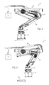
FIGS. 2-3 are side and end views of FIG. 1.
FIGS. 4-6 are side views of FIG. 1 showing the apparatus in pick, mid-move, and place positions; FIGS. 4A-6A being identical to FIGS. 4-6 but with the overhead I-beams removed to expose and thus better show the four-bar linkages.
FIGS. 7-8 are perspective views of a bottle being lifted by vacuum, with a bellow-shaped seal engaging the shoulder of the bottle, FIG. 7 showing the whole bottle, FIG. 8 showing a vertical cross section through FIG. 7 to better show a position and shape of the seal.
FIGS. 9-10 are side cross sectional views of FIG. 8, FIG. 9 showing a bottle cap present, FIG. 10 showing a bottle cap missing.
FIG. 11 is an exploded view of FIG. 7, showing the bellow-shaped seal and seal-supporting structure and showing the absorber-supported plug for engaging a top of the bottle or bottle cap.
FIGS. 12-13 are top and side views of FIG. 7.
FIGS. 14-15 are cross sections taken along lines XIV-XIV and XV-XV in FIGS. 12-13.
FIG. 16 is a new container with modified shoulder having indentations and ribs.
FIGS. 17-19 are side, top, and bottom perspective views of a modified bellow-shaped seal for engaging the modified shoulder of the bottle of FIG. 16.
FIG. 20 is a cross section showing the modified seal of FIG. 17 engaging the modified bottle's shoulder of FIG. 16.
DETAILED DESCRIPTION OF PREFERRED EMBODIMENT
The present material handling apparatus 50 (FIG. 1) includes a robot arm 51 (FIG. 1) supporting a packing head 52 for automatically picking up an array of bottles 53 (also called “containers” herein) (such as 1 gallon milk bottles, or juice bottles, or water jugs, or the like) from a collection station 54 (FIGS. 4, 4A) and placing them into palleted containers 55 (FIGS. 6, 6A). The robot arm 51 includes electro-mechanical actuators 56 and 57 (FIG. 1) for operating first and second four- bar linkages 58 and 59 to lift, extend, and then lower the array of bottles 53 as desired. One of the structural links in each of the four-bar linkages is a hollow tube for communicating air flow (i.e. vacuum) along the robotic arm 51 to the packing head 52, thus integrating vacuum communication for the head into the robotic arm components. The fact that the tubular members double as a structural support and also as a vacuum line simplifies the assembly, eliminating several “extra” hoses and components that used to be attached to a side of the robot arm and that would wear out from rubbing against the robot arm during repeated movement of the robot arm. The resulting assembly is a much more robust and durable and integrated assembly. Also, the present packing head includes bottle-shoulder-engaging seals allowing it to lift and pack all of the one-gallon plastic milk bottles in a given array at the collection station, the even if one of the bottles is missing a bottle cap. It is contemplated that the apparatus 50 can be adapted for bottles and containers of different sizes, different materials, different shapes, and different geometric arrays/patterns.
The illustrated pick-and-place apparatus 50 (FIG. 1) includes two four- bar linkages 58, 59 and three multi-bottle lifting/packing heads 52 for lifting a plurality of bottles 53 (twelve bottle illustrated) in an end-of-conveyor collection station 54. The apparatus 50 includes an overhead support structure including a pair of overhead beams 60 and wall-fixing end-of-beam brackets 61. Actuators 56, 57 are mounted to the beams 60 at location identified by axis 61A. The upper four-bar linkage 58 (FIG. 4A) includes a top elongated link 62 pivoted to support brackets 63 attached between the beams 60. (The support brackets 63 form a stationary link in the four-bar linkage 58.) The four-bar linkage 58 further includes a bottom elongated link 64 connected to the actuator 56, and a T-shaped knee link 65 pivoted between links 62 and 64. The lower four-bar linkage 59 includes an outer elongated link 66 connected to knee link 65, an inner elongated link 67 connected to knee link 65, and T-shaped head-carrying end link 68 between the ends of elongated links 66 and 67. The actuator 57 is connected to the inner elongated link 67 by an actuator rod 69 extending between an actuator arm 70 of the actuator 57 and middle of the link 67. The rotation of the actuators 56 and 57 are timed so that the four- bar linkages 58 and 59 first vertically raise the packing head 52 while carrying the array of bottles 53 (compare FIGS. 4-5, and compare FIGS. 4A-5A), and then laterally move and lower the bottles 53 (compare FIGS. 5-6, and compare FIGS. 5A-6A) to deposit the bottles on pallets in a packing station. Specifically, FIGS. 4-6 are side views of FIG. 1 showing the apparatus 50 in pick, mid-move, and place positions; and FIGS. 4A-6A are identical to FIGS. 4-6 but with the overhead parallel beams removed to expose and thus better show the four- bar linkages 56, 57. The movement and timing of actuators 56 and 57 are generally known in the art such that a detailed description of their operation is not necessary for persons skilled in this art.
Four-bar linkages and pick-and-place apparatus are generally well known in the art, such that a detailed description of the present structure is not required herein for persons skilled in this art to understand the present innovation. Basically, the illustrated four-bar linkages each include 4 rigid links pivoted at four pivot points so that they move with a known path when one of the links is held stationary and another link in each linkage is moved. More specifically, the first four bar linkage includes a stationary link defined by a stationary support structure having two of the pivot points. When one of the links is moved, the opposite end of the first four bar linkage moves along a known path. The second of the four-bar linkages includes an anchoring structure mounted to the outermost link of the first four-bar linkage (i.e. at its end). An outer end of the second four-bar linkage moves along a known path when one of the links in the second four-bar linkage is moved relative to the anchoring structure. First and second actuators are connected to the first and second four-bar linkages, respectively, for moving the four bar linkages in a predetermined sequence. The lengths of the links in both four bar linkages are chosen so that a packing head mounted to an outermost link in the second four bar linkage is maintained in a horizontal “level” condition. This allows for controlled but quick movement of a packing head on the end of the second four-bar linkage, while maintaining a level orientation of the packing head.
Specifically, the illustrated upper four-bar linkage 58 includes four links defined by components 62, 63, 64, and 65 to define four pivot points. When the first actuator 56 forces bottom link 64 to rotate upward, the interaction of links 62-65 cause the top link 62 to also rotate upward (such that it remains generally parallel the bottom link 64) and cause the knee link 65 to move a known distance and rotation. When the second actuator 57 causes the inner link 67 to rotate, the interaction of links 65, 66, 67, 68 cause the outer link 66 to also rotate (such that it remains generally parallel the inner link 67). The net result is that the packing head 52 remains horizontal during the movement of the robot arm as the bottles are lifted from the collection station 54 and placed in the palleted containers 55. Restated, the packing head is moved with a quick and consistent reciprocating motion along a predetermined path while remaining level, moving from the pickup station (e.g. at an end of a bottle-filling conveyor) to the drop-off station (e.g. on a pallet). Notably, a controller controls movement of the robot arm by controlling the two actuators, thus allowing the speed and timing (and final height) of the packing head to be closely and accurately controlled.
FIG. 4A illustrates the vacuum source 72 connected by hose 73 to the vacuum-conveying passageway 74 within the top link 62. The passageway 74 extends to a second hose 75 that extends across the knee link 65 to the vacuum-conveying passageway 76 within the outer link 66. A third hose 77 extends from the passageway 76 to the head vacuum manifold 78 of the packing head 52. As will be understood by persons skilled in this art and shown by comparing FIGS. 4-6 (and FIGS. 4A-6A), the hoses 73, 75, 77 undergo some flexure and movement between hose-supporting connection points during movement of the apparatus 50, but the overall movement and flexure of the hoses is minimized, and further the hoses are in partially protected out-of-the-way positions, thus leading to a much more robust and longlasting source-to-head vacuum supply system.
FIGS. 7-8 are perspective views of a bottle being lifted by vacuum, with a bellow-shaped seal engaging the shoulder of the bottle, FIG. 7 showing the whole bottle, FIG. 8 showing a vertical cross section through FIG. 7 to better show a position and shape of the seal and showing vacuum passages. FIGS. 9-10 are side cross sectional views of FIG. 8, FIG. 9 showing a bottle cap present, FIG. 10 showing a bottle cap missing.
FIG. 11 is an exploded view of FIG. 7, showing the bellow-shaped seal and seal-supporting structure and showing an absorber-supported plug for engaging a top of the bottle or bottle cap. FIGS. 12-13 are top and side views of FIG. 7; and FIGS. 14-15 are cross sections taken along lines XIV-XIV and XV-XV in FIGS. 12-13.
Packing heads are well known in the art, such that a detailed description is not required for persons skilled in this art. The illustrated packing head 52 (FIG. 11) includes top and bottom plates 80 and 81 defining a cavity 82 for communicating vacuum from the hose 77 to individual bottle-lift stations on the packing head 52. A bottle-top-engaging plug 83 (also called an “adapter” herein) is located inside the seal and configured to engage the bottle cap (when present) and shaped to cover the bottle opening (when the bottle cap is missing). Specifically, the plug 83 includes a lower surface shaped to engage a top of a bottle cap 84 (FIG. 9), or if the cap is missing, engage a top 53′ of the bottle 53 itself (i.e. cover the bottle opening) (FIG. 10). A shock absorber 85 (FIG. 11) extends through and is mounted in a hole 85′ in the top plate 80 using a retainer 86 and flat seal 87. The shock absorber 85 includes a resiliently-supported spring-biased shaft 88 extending to and carrying the plug 83. The plug 83 can be attached to the shaft by various means, the illustrated arrangement including two set screws. The shock absorber 85 is biased downward, but permits vertical movement of the shaft 88 and plug 83. This allows the plug 83 to stably engage a bottle cap, or if the bottle cap is missing, stably/sealingly engage a top of the bottle 53. Notably, when vacuum is applied, the bellow-shaped seal 90 described below will compress against the bottle's shoulder and compress vertically as the bottle 53 is lifted a short distance by the vacuum force, with the shock absorber 85 compensating to allow that movement.
The apparatus 50 (FIG. 11) includes a novel packing head 52 with bottle-shoulder-engaging bellow-shaped seals 90. The seals 90 allow all bottles 53 in a given array at the collection station to be lifted, the even if one or more of the bottles 53 is missing a bottle cap. The bellow-shaped seal 90 is mounted using a bowl retainer 91 and flat ring seal 92 attached by screws to the bottom plate 81 around a hole 93 in the bottom plate 81. The hole 93 is larger than the plug 83 so that air (i.e. vacuum) can flow from inside the bellow-shaped seal 90 up through the hole 93 into the vacuum-conveying cavity 82 of the packing head 52. The bellow-shaped seal 90 includes an upper mounting ring portion 95 for sealingly engaging the bowl retainer 91, and further includes downwardly-extending resilient ring portions 96, 97 defining a bellow-shaped structure. The ring portions 96, 97 are bellow-shaped and resilient, and their lower edge 98 is thinned and extends radially outward. The lower edge 98 is shaped to flex and abuttingly sealingly engage the shoulder 53″ that extends around the threaded cap-engaging neck of the bottle 53. The illustrated lower edge 98 forms a relatively uniform circular shape slightly larger than the bottle cap 84, and engages a shoulder on the bottle located generally around the bottle's neck that defines the bottle's opening (and which is normally covered by a bottle cap).
Recently, some bottle-filling companies have begun using a new container 100 (FIG. 16) with a modified shoulder 101 that does not include a uniformly smooth and circular shoulder like shoulder 54″. Instead, the modified shoulder 101 has indentations and undulations forming recesses and ribs in the shoulder. The illustrated modified shoulder 101 includes indentations forming inverted U-shaped recesses 102 that intrude into the shoulder area, and further includes multiple ribs 103 (three ribs being illustrated) with upper ends that intrude into the shoulder area. The bellow-shaped seal 90A (FIGS. 17-19) is identical to seal 90 but is modified to include bumps 105 on the lower edge 98A. The bumps 105 extend circumferentially short distances, and are located to correspond to and fill the U-shaped recesses 102. Specifically, the bumps 105 have a length sufficient to fill the recesses 102, and a width sufficient to not interferingly engage the end of any ribs 103. Thus, abuttingly engage the shoulder 101 and allow a vacuum to be drawn inside the seal 90A despite the existence of the recesses 102 and ribs 103 in the bottle 100.
It is to be understood that variations and modifications can be made on the aforementioned structure without departing from the concepts of the present invention, and further it is to be understood that such concepts are intended to be covered by the following claims unless these claims by their language expressly state otherwise.

Claims (6)

The embodiments of the invention in which an exclusive property or privilege is claimed are defined as follows:
1. A material handling apparatus for packing bottles, comprising:
a packing head using vacuum to lift bottles;
a robot arm including at least one actuator operably connected to a first and a second four-bar linkages with the first four-bar linkage operably supporting the second four-bar linkage for movement and the second four-bar linkage operably supporting the package head for movement between a bottle-collection station and a bottle-palleted station, one link of each of the first and second four-bar linkages being a tubular elongated structural member forming a vacuum-conveying internal passageway extending along the robot arm, another link of the first four-bar linkage being formed by stationary support brackets, and two additional links of the first four-bar linkage supporting the one link for movement relative to the support brackets; and
a vacuum system including a vacuum source, a first hose connecting the vacuum source to a first end of the vacuum-conveying internal passageway in the first four-bar linkage, and a second hose connecting a second end of the vacuum-conveying internal passageway of the first linkage to a first end of the vacuum-conveying internal passageway of the second linkage, and a third hose connecting a second end of the vacuum-conveying internal passageway of the second linkage to the packing head, to thus form a vacuum-conveying continuous passageway that extends from the vacuum source through the first, second, and third hoses and through the vacuum-conveying internal passageways of the first and second four-bar linkages to the packing head.
2. A material handling apparatus adapted to lift bottles each having a bottle top defining an opening normally closed by a bottle cap and a bottle shoulder around the opening, comprising:
a packing head with at least one bottle-lifting station including bottle-engaging members each having a shoulder-engaging seal and a plug inside the seal defining a continuously-open vacuum-drawing space for drawing a vacuum on an associated one of the bottle tops between the seal and plug, the plug being shaped to directly contact the bottle cap when present on the associated one of the bottles and also shaped to sealingly cover an associated one of the openings when a bottle cap is missing on the associated one of the bottles while in both circumstances permitting vacuum to be drawn between the plug seal; and
a vacuum source connected to the vacuum-drawing space of each of the bottle-engaging members for drawing a vacuum inside the seal for suctionally gripping the bottles using the seal and shoulder to lift the bottles both when the cap is present and when the cap is missing.
3. The apparatus of claim 2, wherein the at least one bottle-lifting station includes a plurality of bottle-lifting stations.
4. The apparatus of claim 2, wherein the seal includes a bellow-shaped section constructed to foldingly collapse.
5. The apparatus of claim 2, including a bottle-opening-covering adapter inside the seal having a downwardly concave shape configured to matingly engage a top and sides of the bottle cap and that is also shaped to engage a top surface of the bottle when the bottle cap is missing.
6. A material handling apparatus adapted to lift bottles each having a bottle top defining an opening normally closed by a bottle cap and a bottle shoulder around the opening, comprising:
a packing head with at least one bottle-lifting station including bottle-engaging members each having a shoulder-engaging seal and a plug inside the seal defining a vacuum-drawing space for drawing a vacuum on an associated one of the bottle tops between the seal and plug, the plug being shaped to directly contact the bottle cap when present on the associated one of the bottles and also shaped to sealingly cover an associated one of the openings when a bottle cap is missing on the associated one of the bottles while in both circumstances permitting vacuum to be drawn between the plug and seal;
the bottle-engaging members further including a spring-biased shock absorber movably supporting the plug for sealing engagement when the bottle cap is present and when the bottle cap is not present; and
a vacuum source connected to the vacuum-drawing space of each of the bottle-engaging members for drawing a vacuum inside the seal for suctionally gripping the bottles using the seal and shoulder to lift the bottles both when the associated cap is present and when the associated cap is missing.
US14/636,564 2014-03-03 2015-03-03 Robot with packing head and integrated vacuum arm Expired - Fee Related US9796495B2 (en)

Priority Applications (1)

Application Number Priority Date Filing Date Title
US14/636,564 US9796495B2 (en) 2014-03-03 2015-03-03 Robot with packing head and integrated vacuum arm

Applications Claiming Priority (2)

Application Number Priority Date Filing Date Title
US201461947139P 2014-03-03 2014-03-03
US14/636,564 US9796495B2 (en) 2014-03-03 2015-03-03 Robot with packing head and integrated vacuum arm

Publications (2)

Publication Number Publication Date
US20150246740A1 US20150246740A1 (en) 2015-09-03
US9796495B2 true US9796495B2 (en) 2017-10-24

Family

ID=54006412

Family Applications (1)

Application Number Title Priority Date Filing Date
US14/636,564 Expired - Fee Related US9796495B2 (en) 2014-03-03 2015-03-03 Robot with packing head and integrated vacuum arm

Country Status (1)

Country Link
US (1) US9796495B2 (en)

Cited By (8)

* Cited by examiner, † Cited by third party
Publication number Priority date Publication date Assignee Title
US10029369B1 (en) * 2017-06-09 2018-07-24 Precise Automation, Inc. Collaborative robot
US20180265234A1 (en) * 2015-10-08 2018-09-20 Gima S.P.A. Station for inserting products into box-like bodies of different types
US10173323B2 (en) * 2017-06-09 2019-01-08 Precise Automation, Inc. Collaborative robot
US20190084701A1 (en) * 2015-10-08 2019-03-21 Gima S.P.A. Machine for forming and filling box-like bodies of different types
CN109542171A (en) * 2018-11-27 2019-03-29 盐城吉大智能终端产业研究院有限公司 A kind of multifunctional intelligent terminal and its application method
CN109955223A (en) * 2019-03-01 2019-07-02 达闼科技(北京)有限公司 A kind of robot inner frame and robot
CN112166013A (en) * 2018-07-16 2021-01-01 星猿哲机器人全球有限公司 Robotic system for selecting, sorting and placing a plurality of random and new articles
US11713147B2 (en) 2019-07-30 2023-08-01 Anheuser-Busch Inbev S.A. Article picking and treating apparatus

Families Citing this family (9)

* Cited by examiner, † Cited by third party
Publication number Priority date Publication date Assignee Title
GB2517163A (en) * 2013-08-13 2015-02-18 Universal Balancing Ltd An apparatus for transporting a rotor
CN105346753B (en) * 2015-10-23 2018-05-04 双峰格雷斯海姆医药玻璃(丹阳)有限公司 A kind of automatic bottle standing machinery hand
CN105538303B (en) * 2016-02-22 2017-04-26 河北工业大学 Three-degree-of-freedom high-altitude mounting manipulator for large plates
CN107010255A (en) * 2017-06-14 2017-08-04 湃思科技(苏州)有限公司 Multiaxis feeding device
DE202017104004U1 (en) * 2017-07-05 2018-10-09 Autefa Solutions Germany Gmbh Gripping device for containers
US11345626B1 (en) * 2018-07-23 2022-05-31 Gerresheimer Glass Inc. Glass manufacturing apparatus and method
CN110733893A (en) * 2019-11-13 2020-01-31 温州佳德包装机械有限公司 Dynamic tracking online material taking and placing mechanism
CN110722546A (en) * 2019-11-13 2020-01-24 温州佳德包装机械有限公司 Multipurpose three-axis mechanical arm
CN114603568A (en) * 2020-12-08 2022-06-10 广东博智林机器人有限公司 Robot arm device and coating robot

Citations (38)

* Cited by examiner, † Cited by third party
Publication number Priority date Publication date Assignee Title
US1947609A (en) 1928-02-21 1934-02-20 Capstan Glass Co Vessel transferring mechanism
US1959512A (en) 1933-05-25 1934-05-22 North American Refractories Brick transferring apparatus
US1987336A (en) 1930-04-10 1935-01-08 Pacific Egg Producers Cooperat Egg pick-up apparatus
US2867185A (en) 1955-12-15 1959-01-06 Lobdell Emery Mfg Company Transfer mechanism
US2904192A (en) 1956-11-23 1959-09-15 Gen Electric Lamp transfer apparatus
US2997242A (en) 1956-08-23 1961-08-22 Air Shields Therapeutic fog generator
US3039623A (en) 1958-03-10 1962-06-19 Sehn Automatic press material handling apparatus
US3406837A (en) 1966-10-13 1968-10-22 Erie Eng Co Lifting and swinging work transfer device
US3463329A (en) 1967-05-18 1969-08-26 Sylvania Electric Prod Material transfer device with parallel link frame
US3648853A (en) 1970-04-03 1972-03-14 Erie Eng Co Vacuum work pick-up attachment for work device
US3685624A (en) 1970-06-05 1972-08-22 Paul F Paddock Device to pack articles in boxes
US3753453A (en) 1968-09-20 1973-08-21 Dover Corp Fluid handling apparatus
US3912317A (en) 1974-07-10 1975-10-14 Shiroyama Kogyo Kk Vacuum suction type manipulator
US3971190A (en) * 1975-02-20 1976-07-27 A-T-O Inc. Article transfer apparatus having releasable rods
US4364707A (en) 1980-05-06 1982-12-21 Advanced Semiconductor Materials Die Bonding Inc. Object transport apparatus
US4451197A (en) 1982-07-26 1984-05-29 Advanced Semiconductor Materials Die Bonding, Inc. Object detection apparatus and method
US4787812A (en) 1983-02-24 1988-11-29 Goepfert Reinhard Apparatus for lifting arrays of paving stones and the like
US4975016A (en) 1986-11-05 1990-12-04 Etablissements Pellenc et Motte, Centre National Du Machinisme Agricole Du Genie Rural, des Eaux et des Forets (csm agrcr) Automated machine for detection and grasping of objects
US5007784A (en) 1989-01-20 1991-04-16 Genmark Automation Dual end effector robotic arm
US5060455A (en) 1990-06-28 1991-10-29 Ameco Corporation Robotic case packing system and method
US5536135A (en) 1995-04-19 1996-07-16 Valley Equipment Company Material transfer apparatus
US5553442A (en) 1994-10-06 1996-09-10 James River Paper Company, Inc. Robotic system for mixing articles in containers
US5735200A (en) 1996-07-01 1998-04-07 Chrysler Corporation Stamping press loader
US5797249A (en) 1994-11-10 1998-08-25 Hartness International, Inc. Continuous motion case packing apparatus and method
US5984623A (en) 1998-03-31 1999-11-16 Abb Flexible Automation, Inc. Carrier feed vaccum gripper
US6592323B1 (en) 2002-02-12 2003-07-15 Tsung-Chang Hsieh Plate member carrier
US7086941B2 (en) * 2004-06-28 2006-08-08 Ennis G Thomas Multiposition vehicle exhaust recovery system
US7185685B2 (en) 2004-07-13 2007-03-06 Wolfgang Von Meyerinck Head piece for refueling systems
US7389826B2 (en) 2004-09-28 2008-06-24 Oshkosh Truck Corporation Firefighting agent delivery system
US20080246290A1 (en) 2004-06-23 2008-10-09 Kenny Johansson Method for Manufacturing a Gripping Means Having Integrated Vacuum Channels
US7474072B1 (en) * 2006-10-27 2009-01-06 Bakery Holdings, Llc Case packing robot
US7644558B1 (en) 2006-10-26 2010-01-12 Fallas David M Robotic case packing system
US7686564B2 (en) 2003-10-14 2010-03-30 Krones Ag Palletizing device
US7856797B2 (en) 2008-04-03 2010-12-28 Arm Automation, Inc. Automated collector device and methods
US7950708B2 (en) 2008-08-15 2011-05-31 Amf Automation Technologies, Inc. Programmable zoned end effector
US8251415B2 (en) 2010-04-20 2012-08-28 AMF automation Technologies, LLC End effector with suction cups having internal valves
US8528955B2 (en) 2011-01-24 2013-09-10 AMF automation Technologies, LLC Robot end effector with cable management
US20130232918A1 (en) 2010-05-25 2013-09-12 AMF automation Technologies, LLC Method of Forming U-Shaped Insert and Inserting About Goods in Container

Patent Citations (38)

* Cited by examiner, † Cited by third party
Publication number Priority date Publication date Assignee Title
US1947609A (en) 1928-02-21 1934-02-20 Capstan Glass Co Vessel transferring mechanism
US1987336A (en) 1930-04-10 1935-01-08 Pacific Egg Producers Cooperat Egg pick-up apparatus
US1959512A (en) 1933-05-25 1934-05-22 North American Refractories Brick transferring apparatus
US2867185A (en) 1955-12-15 1959-01-06 Lobdell Emery Mfg Company Transfer mechanism
US2997242A (en) 1956-08-23 1961-08-22 Air Shields Therapeutic fog generator
US2904192A (en) 1956-11-23 1959-09-15 Gen Electric Lamp transfer apparatus
US3039623A (en) 1958-03-10 1962-06-19 Sehn Automatic press material handling apparatus
US3406837A (en) 1966-10-13 1968-10-22 Erie Eng Co Lifting and swinging work transfer device
US3463329A (en) 1967-05-18 1969-08-26 Sylvania Electric Prod Material transfer device with parallel link frame
US3753453A (en) 1968-09-20 1973-08-21 Dover Corp Fluid handling apparatus
US3648853A (en) 1970-04-03 1972-03-14 Erie Eng Co Vacuum work pick-up attachment for work device
US3685624A (en) 1970-06-05 1972-08-22 Paul F Paddock Device to pack articles in boxes
US3912317A (en) 1974-07-10 1975-10-14 Shiroyama Kogyo Kk Vacuum suction type manipulator
US3971190A (en) * 1975-02-20 1976-07-27 A-T-O Inc. Article transfer apparatus having releasable rods
US4364707A (en) 1980-05-06 1982-12-21 Advanced Semiconductor Materials Die Bonding Inc. Object transport apparatus
US4451197A (en) 1982-07-26 1984-05-29 Advanced Semiconductor Materials Die Bonding, Inc. Object detection apparatus and method
US4787812A (en) 1983-02-24 1988-11-29 Goepfert Reinhard Apparatus for lifting arrays of paving stones and the like
US4975016A (en) 1986-11-05 1990-12-04 Etablissements Pellenc et Motte, Centre National Du Machinisme Agricole Du Genie Rural, des Eaux et des Forets (csm agrcr) Automated machine for detection and grasping of objects
US5007784A (en) 1989-01-20 1991-04-16 Genmark Automation Dual end effector robotic arm
US5060455A (en) 1990-06-28 1991-10-29 Ameco Corporation Robotic case packing system and method
US5553442A (en) 1994-10-06 1996-09-10 James River Paper Company, Inc. Robotic system for mixing articles in containers
US5797249A (en) 1994-11-10 1998-08-25 Hartness International, Inc. Continuous motion case packing apparatus and method
US5536135A (en) 1995-04-19 1996-07-16 Valley Equipment Company Material transfer apparatus
US5735200A (en) 1996-07-01 1998-04-07 Chrysler Corporation Stamping press loader
US5984623A (en) 1998-03-31 1999-11-16 Abb Flexible Automation, Inc. Carrier feed vaccum gripper
US6592323B1 (en) 2002-02-12 2003-07-15 Tsung-Chang Hsieh Plate member carrier
US7686564B2 (en) 2003-10-14 2010-03-30 Krones Ag Palletizing device
US20080246290A1 (en) 2004-06-23 2008-10-09 Kenny Johansson Method for Manufacturing a Gripping Means Having Integrated Vacuum Channels
US7086941B2 (en) * 2004-06-28 2006-08-08 Ennis G Thomas Multiposition vehicle exhaust recovery system
US7185685B2 (en) 2004-07-13 2007-03-06 Wolfgang Von Meyerinck Head piece for refueling systems
US7389826B2 (en) 2004-09-28 2008-06-24 Oshkosh Truck Corporation Firefighting agent delivery system
US7644558B1 (en) 2006-10-26 2010-01-12 Fallas David M Robotic case packing system
US7474072B1 (en) * 2006-10-27 2009-01-06 Bakery Holdings, Llc Case packing robot
US7856797B2 (en) 2008-04-03 2010-12-28 Arm Automation, Inc. Automated collector device and methods
US7950708B2 (en) 2008-08-15 2011-05-31 Amf Automation Technologies, Inc. Programmable zoned end effector
US8251415B2 (en) 2010-04-20 2012-08-28 AMF automation Technologies, LLC End effector with suction cups having internal valves
US20130232918A1 (en) 2010-05-25 2013-09-12 AMF automation Technologies, LLC Method of Forming U-Shaped Insert and Inserting About Goods in Container
US8528955B2 (en) 2011-01-24 2013-09-10 AMF automation Technologies, LLC Robot end effector with cable management

Cited By (11)

* Cited by examiner, † Cited by third party
Publication number Priority date Publication date Assignee Title
US20180265234A1 (en) * 2015-10-08 2018-09-20 Gima S.P.A. Station for inserting products into box-like bodies of different types
US20190084701A1 (en) * 2015-10-08 2019-03-21 Gima S.P.A. Machine for forming and filling box-like bodies of different types
US10710754B2 (en) * 2015-10-08 2020-07-14 I.M.A. Industria Macchine Automatiche S.P.A. Machine for forming and filling box-like bodies of different types
US10029369B1 (en) * 2017-06-09 2018-07-24 Precise Automation, Inc. Collaborative robot
US10173323B2 (en) * 2017-06-09 2019-01-08 Precise Automation, Inc. Collaborative robot
US10252420B2 (en) 2017-06-09 2019-04-09 Precise Automation, Inc. Collaborative robot
CN112166013A (en) * 2018-07-16 2021-01-01 星猿哲机器人全球有限公司 Robotic system for selecting, sorting and placing a plurality of random and new articles
CN112166013B (en) * 2018-07-16 2023-09-26 星猿哲机器人全球有限公司 Robotic system for picking, sorting and placing a plurality of random and new articles
CN109542171A (en) * 2018-11-27 2019-03-29 盐城吉大智能终端产业研究院有限公司 A kind of multifunctional intelligent terminal and its application method
CN109955223A (en) * 2019-03-01 2019-07-02 达闼科技(北京)有限公司 A kind of robot inner frame and robot
US11713147B2 (en) 2019-07-30 2023-08-01 Anheuser-Busch Inbev S.A. Article picking and treating apparatus

Also Published As

Publication number Publication date
US20150246740A1 (en) 2015-09-03

Similar Documents

Publication Publication Date Title
US9796495B2 (en) Robot with packing head and integrated vacuum arm
US9174832B2 (en) Capping apparatus and capping system for bottle filling device
US10214407B2 (en) Systems for cooling hot-filled containers
US9695029B2 (en) Container-processing machine for processing containers
EP2389329B1 (en) Method and system for handling containers
US20110254298A1 (en) End Effector with Suction Cups Having Internal Valves
US9340402B2 (en) Lifting element with extensible rinse sleeve
US8528955B2 (en) Robot end effector with cable management
US20080118340A1 (en) Method for Palletizing Bottles with Interleaving of Layers
US2863579A (en) Case unloader with bottle rejecting head
EP2569217B1 (en) Method and device for filling containers
US20060236656A1 (en) Vessel-filling apparatus
US11485530B2 (en) Method to transfer and place articles into outer packages and apparatus to carry out the method
US10858132B2 (en) Disposable production line for filling and finishing a product
CN112299342B (en) Rotary vacuum bottle sealing machine
CN102700771B (en) Stower
CN101691141A (en) Aluminum box packing machine
US20070059152A1 (en) Methosand device for handling rod-shaped objects
US6523874B1 (en) Packaging apparatus and method
US20160137433A1 (en) Palletiser for loading and packaging unstable containers
CN205313030U (en) Equipment of lid is rolled in pressurization
CN113666324A (en) Soft barrel fresh mineral water filling device, process and bottle supporting equipment
EP3088351A1 (en) Packaging method including inversion and labeling steps on a container
JP5481734B2 (en) Mushroom harvesting method, mushroom harvesting device and mushroom harvesting ring
CN217864940U (en) Unloading vanning equipment of shaping feeding bottle

Legal Events

Date Code Title Description
AS Assignment

Owner name: INTEGRATED PACKAGING MACHINERY, LLC, MICHIGAN

Free format text: ASSIGNMENT OF ASSIGNORS INTEREST;ASSIGNORS:BODEN, WILLIAM;KEECH, LARRY;LAMB, PAUL;AND OTHERS;SIGNING DATES FROM 20160803 TO 20160831;REEL/FRAME:039855/0877

STCF Information on status: patent grant

Free format text: PATENTED CASE

FEPP Fee payment procedure

Free format text: MAINTENANCE FEE REMINDER MAILED (ORIGINAL EVENT CODE: REM.); ENTITY STATUS OF PATENT OWNER: SMALL ENTITY

LAPS Lapse for failure to pay maintenance fees

Free format text: PATENT EXPIRED FOR FAILURE TO PAY MAINTENANCE FEES (ORIGINAL EVENT CODE: EXP.); ENTITY STATUS OF PATENT OWNER: SMALL ENTITY

STCH Information on status: patent discontinuation

Free format text: PATENT EXPIRED DUE TO NONPAYMENT OF MAINTENANCE FEES UNDER 37 CFR 1.362

FP Lapsed due to failure to pay maintenance fee

Effective date: 20211024