US9790988B1 - Self-adjusting bushing bearing having a springy element - Google Patents
Self-adjusting bushing bearing having a springy element Download PDFInfo
- Publication number
- US9790988B1 US9790988B1 US14/961,368 US201514961368A US9790988B1 US 9790988 B1 US9790988 B1 US 9790988B1 US 201514961368 A US201514961368 A US 201514961368A US 9790988 B1 US9790988 B1 US 9790988B1
- Authority
- US
- United States
- Prior art keywords
- bearing
- leaf spring
- self
- segments
- shaft
- Prior art date
- Legal status (The legal status is an assumption and is not a legal conclusion. Google has not performed a legal analysis and makes no representation as to the accuracy of the status listed.)
- Expired - Fee Related, expires
Links
Images


Classifications
-
- F—MECHANICAL ENGINEERING; LIGHTING; HEATING; WEAPONS; BLASTING
- F16—ENGINEERING ELEMENTS AND UNITS; GENERAL MEASURES FOR PRODUCING AND MAINTAINING EFFECTIVE FUNCTIONING OF MACHINES OR INSTALLATIONS; THERMAL INSULATION IN GENERAL
- F16C—SHAFTS; FLEXIBLE SHAFTS; ELEMENTS OR CRANKSHAFT MECHANISMS; ROTARY BODIES OTHER THAN GEARING ELEMENTS; BEARINGS
- F16C33/00—Parts of bearings; Special methods for making bearings or parts thereof
- F16C33/02—Parts of sliding-contact bearings
- F16C33/04—Brasses; Bushes; Linings
- F16C33/06—Sliding surface mainly made of metal
- F16C33/10—Construction relative to lubrication
- F16C33/1005—Construction relative to lubrication with gas, e.g. air, as lubricant
-
- F—MECHANICAL ENGINEERING; LIGHTING; HEATING; WEAPONS; BLASTING
- F16—ENGINEERING ELEMENTS AND UNITS; GENERAL MEASURES FOR PRODUCING AND MAINTAINING EFFECTIVE FUNCTIONING OF MACHINES OR INSTALLATIONS; THERMAL INSULATION IN GENERAL
- F16C—SHAFTS; FLEXIBLE SHAFTS; ELEMENTS OR CRANKSHAFT MECHANISMS; ROTARY BODIES OTHER THAN GEARING ELEMENTS; BEARINGS
- F16C17/00—Sliding-contact bearings for exclusively rotary movement
- F16C17/02—Sliding-contact bearings for exclusively rotary movement for radial load only
- F16C17/03—Sliding-contact bearings for exclusively rotary movement for radial load only with tiltably-supported segments, e.g. Michell bearings
-
- F—MECHANICAL ENGINEERING; LIGHTING; HEATING; WEAPONS; BLASTING
- F16—ENGINEERING ELEMENTS AND UNITS; GENERAL MEASURES FOR PRODUCING AND MAINTAINING EFFECTIVE FUNCTIONING OF MACHINES OR INSTALLATIONS; THERMAL INSULATION IN GENERAL
- F16C—SHAFTS; FLEXIBLE SHAFTS; ELEMENTS OR CRANKSHAFT MECHANISMS; ROTARY BODIES OTHER THAN GEARING ELEMENTS; BEARINGS
- F16C25/00—Bearings for exclusively rotary movement adjustable for wear or play
- F16C25/02—Sliding-contact bearings
- F16C25/04—Sliding-contact bearings self-adjusting
-
- F—MECHANICAL ENGINEERING; LIGHTING; HEATING; WEAPONS; BLASTING
- F16—ENGINEERING ELEMENTS AND UNITS; GENERAL MEASURES FOR PRODUCING AND MAINTAINING EFFECTIVE FUNCTIONING OF MACHINES OR INSTALLATIONS; THERMAL INSULATION IN GENERAL
- F16C—SHAFTS; FLEXIBLE SHAFTS; ELEMENTS OR CRANKSHAFT MECHANISMS; ROTARY BODIES OTHER THAN GEARING ELEMENTS; BEARINGS
- F16C2226/00—Joining parts; Fastening; Assembling or mounting parts
- F16C2226/50—Positive connections
- F16C2226/60—Positive connections with threaded parts, e.g. bolt and nut connections
Definitions
- the present disclosure relates to bushing bearings, and more specifically self-adjusting bushing bearings having one or more spring elements.
- U.S. Pat. No. 8,870,459 discloses a self-adjusting bushing bearing for engagement with a bearing shaft.
- a bearing housing is provided.
- a bearing sub-assembly is received inside of the bearing housing and the bearing sub-assembly is adapted to receive the bearing shaft.
- the bearing sub-assembly has at least two bearing segments and at least one springy element engaged with the bearing housing which compresses the bearing segments toward one another.
- U.S. Provisional Patent Application No. 62/258,695 disclosures a self-adjusting bushing bearing with a shaft seal for engaging a bearing shaft.
- the self-adjusting bushing bearing has a plurality of bearing segments configured to receive a bearing shaft therein.
- a springy element engages an outer surface of the plurality of bearing segments and biases the plurality of bearing segments towards the bearing shaft.
- a shaft seal coupled to the springy element is configured to contact the bearing shaft when the bearing shaft is received in the plurality of bearing segments so as to create an operable seal between the plurality of bearing segments and the bearing shaft.
- the present disclosure relates to self-adjusting bushing bearings having at least one springy element.
- the self-adjusting bushing bearing has a bearing subassembly that is configured to be received in a housing and also has a plurality of bearing segments that together are configured to receive a shaft therein.
- a springy element biases the plurality of bearing segments radially inwardly towards the shaft.
- the springy element is mated with at least one bearing segment in the plurality of bearing segments.
- FIG. 1 is cross-section view of an exemplary Self-Adjusting Bushing Bearing with a springy element, shown as three leaf springs.
- FIG. 2 is a view of section 2 - 2 taken in FIG. 1 .
- FIG. 3 is a side view of an exemplary leaf spring in accordance with the device shown in FIG. 1 .
- FIG. 4 is a top view of the leaf spring shown in FIG. 3 .
- FIG. 5 is an exploded view of the device shown in FIG. 1 .
- FIG. 6 is an exploded close-up view of the device shown in FIG. 5 .
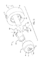
- FIG. 7 is a perspective view of another exemplary Self-Adjusting Bushing Bearing.
- FIG. 8 is an exploded view of the device shown in FIG. 7 .
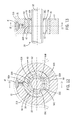
- FIG. 9 is a cross-section view of the device shown in FIG. 7 .
- FIG. 10 is a view of section 10 - 10 taken in FIG. 9 .
- FIG. 11 is an exploded perspective view of another exemplary Self-Adjusting Bushing Bearing.
- FIG. 12 is a cross-section view of the device shown in FIG. 11 .
- FIG. 13 is a view of section 13 - 13 taken in FIG. 13 .
- FIG. 14 is an exploded perspective view of another exemplary device similar to the device shown in FIG. 11 , but having no shaft seals on the ends.
- FIG. 15 is a cross-section view of the device shown in FIG. 14 .
- FIG. 16 is a view of section 16 - 16 taken in FIG. 15 .
- FIG. 17 is a perspective view of another exemplary Self-Adjusting Bushing Bearing similar to the device shown in FIG. 14 , but having a space between the annular ring of the biasing element and the bearing segments.
- FIG. 18 is a cross-sectional view of the biasing element from the device shown in FIG. 17 .
- FIG. 19 is a cross-section view of the device shown in FIG. 17 .
- FIG. 20 is a view of section 20 - 20 taken in FIG. 19 .
- FIG. 21 is an exploded perspective view of another exemplary Self-Adjusting Bushing Bearing similar to the device shown in FIG. 14 , but shown with the biasing element as three cylindrical segments.
- FIG. 22 is a cross-section view of the device shown in FIG. 21 .
- FIG. 23 is a view of section 23 - 23 taken in FIG. 22 .
- FIG. 24 is an end view of another exemplary Self-Adjusting Bushing Bearing similar to the device shown in FIG. 1 , but having additional leaf springs stacked together.
- FIG. 25 is an exploded perspective view of another exemplary device similar to the device shown in in FIG. 8 , but having a second biasing element in addition to the opposing end caps.
- FIG. 26 is an end view of another exemplary Self-Adjusting Bushing Bearing similar to the device shown in FIG. 1 , but replacing the leaf springs with coil springs.
- bearings generally require tight machining tolerances to ensure close contact between the bearing and the shaft received therein.
- This close contact diminishes as the components wear through operation, limiting the life of the bearing.
- O-ring elastomers are stretched around the outer surfaces of multi-segment bearings to bias the bearing segments towards each other, creating close contact with the shaft received therein.
- the present inventors have found that the elastomeric materials used may not be able to withstand the desired operating conditions.
- the bearing application may require withstanding high temperatures, chemical environments that are incompatible with the material, or applications requiring a high or low pH.
- the elastomeric materials used in these bearings may have a limited “shelf life” and can become brittle and crack over time.
- bearings cannot accommodate a relatively light preload, a low load versus deflection characteristic, or relatively large travel, such as those occurs with ceiling fans having rotational imbalances. Even in the cases of bearings that incorporate O-ring elastomers to maintain contact between the bearing segment and the shaft, the load versus deflection characteristics may be limited by shape of an O-ring elastomer. Further, the initial preload may not be sufficient for applications that require high initial loads, such as gear trains. In addition, the bearing segments are free to move relative to each other, creating uneven contact with the bearing segments. This movement may reduce the life of the O-ring or bearing segments and may create additional noise during operation.
- FIGS. 1 and 2 show an exemplary self-adjusting bushing bearing (SABB) 30 disposed in a housing 31 .
- the SABB 30 has a bearing subassembly 33 and a springy element 50 , which in this embodiment includes leaf springs 50 A, 50 B, 50 C.
- the bearing subassembly 33 is made up of bearing segments 35 A, 35 B, 35 C that together form a cylindrical shape that is configured to receive a shaft 32 therein.
- Each leaf spring 50 A, 50 B, 50 C is located between the bearing subassembly 33 and the inner periphery 31 A of the housing 31 .
- bearing segments and three leaf springs are shown, other quantities and configurations of bearing segments, leaf springs, or other springy elements may be also used.
- FIGS. 3 and 4 show a close-up view of a leaf spring 50 A having a first end 51 A, a second end 52 A opposite of the first end 51 A, and a projection 53 A located between the first end 51 A and the second end 52 A.
- the leaf spring 50 A is an elongated, six-sided shape and the projection 53 A is a hemispherical projection.
- the material properties and dimension of the leaf springs 50 A, 50 B, 50 C can vary and can be selected based on the particular bearing application.
- a plurality of leaf springs can be stacked on top of each other to create additional biasing force or change the deflection characteristics.
- FIG. 3 shows a leaf spring 50 A in a curved, deflected shape
- the leaf spring 50 A may have a flat shape before installation into the housing 31 .
- the leaf spring 50 A may have a curved shape even before installation into the housing 31 .
- FIG. 3 shows the first end 51 A and second end 52 A of leaf springs 50 A being pointed, each could be truncated, allowing the leaf springs 50 A, 50 B, 50 C to engage each other to help to equally space the bearing segments 35 A, 35 B, 35 C apart.
- the leaf springs 50 A, 50 B, 50 C may be rectangular instead of truncated.
- each leaf spring 50 A, 50 B, 50 C is received in a recess 36 A, 36 B, 36 C within the bearing segment 35 A, 35 B, 35 C to mate the leaf spring 50 A, 50 B, 50 C with the bearing segment 35 A, 35 B, 35 C.
- the first end 51 A, 51 B, 51 C and the second end 52 A, 52 B, 52 C of the leaf spring 50 A, 50 B, 50 C are configured to abut against an inner periphery 31 A of the housing 31 so that each leaf spring 50 A, 50 B, 50 C is deflected radially inwardly and applies a radially inward force at the projection 53 A, 53 B, 53 C.
- each leaf spring 50 A, 50 B, 50 C provides a constant biasing force on each bearing segment 35 A, 35 B, 35 C radially inwardly towards the shaft 32 .
- This constant biasing force maintains constant, close contact between the bearing segment 35 A, 35 B, 35 C and the shaft 32 during operation.
- the present inventors have found that constantly biasing the bearing segment 35 A, 35 B, 35 C against the shaft 32 maintains smooth bearing operation despite wear of these components. Similarly, the close contact allows use of a lower viscosity lubricant 42 between the bearing segment 35 A, 35 B, 35 C and the shaft 32 .
- each leaf spring 50 A, 50 B, 50 C is configured as a triangular shape to avoid interference with adjacent elements in the SABB 30 , which still maintaining contact with the inner periphery 31 A of the housing 31 .
- each leaf spring 50 A, 50 B, 50 C can bias one bearing segment 35 A, 35 B, 35 C
- a leaf spring 50 A, 50 B, 50 C could bias multiple bearing segments 35 A, 35 B, 35 C.
- more than one leaf spring 50 A, 50 B, 50 C may bias one bearing segment 35 A, 35 B, 35 C.
- FIG. 5 shows a packing seal retainer 39 A located next to the bearing subassembly 33 within the housing 31 , followed by a packing seal 38 , seal retainer 39 B, and a retaining ring 40 to retain these structures within the housing 31 .
- the packing seal retainer 39 A, the packing seal 38 , the seal retainer 39 B, and the retaining ring 40 may be disposed on one or both sides of the bearing subassembly 33 .
- FIG. 1 discloses a fill plug 41 that permits a lubricant 42 (not shown) to be added inside the SABB 30 , as disclosed in U.S. Provisional Patent Application No. 62/258,695.
- FIG. 6 further shows each bearing segment 35 A, 35 B, 35 C has a radially outer channel 37 that has opposing sidewalls 37 A and a bottom wall 37 B.
- a recess 36 A ( 36 B and 36 C not shown) is formed in each bottom wall 37 B.
- each leaf spring 50 A, 50 B, 50 C is disposed within a radially outer channel 37 and is configured to abut the opposing sidewalls 37 A and bottom wall 37 B.
- the radial outer channel 37 prevents interference between the leaf spring 50 A, 50 B, 50 C and elements that are adjacent to the bearing subassembly 33 , such as a packing seal retainer 39 A or a packing seal.
- opposing sidewalls 37 A of the radial outer channel 37 prevent the leaf spring 50 A, 50 B, 50 C from rotating about the projection 53 A, 53 B, 53 C.
- FIGS. 7-23 show alternate exemplary SABB 30 embodiments wherein the springy element 50 is a cylindrical body, which in the embodiment shown in FIGS. 7-10 is made up by opposing end caps 60 .
- the opposing end caps 60 have an outer radial surface 61 and an inner radial surface 62 .
- each of the opposing end caps 60 has a projection 63 A, 63 B, 63 C that is triangular prism shaped and axially extends along the inner radial surface 62 .
- FIG. 8 shows that each projection 63 A, 63 B, 63 C mates with a recess 36 A, 36 B, 36 C that axially extends within the outer surface 67 of each bearing segment 35 A, 35 B, 35 C.
- the opposing end caps 60 apply a radially inwardly force at each projection 63 A, 63 B, 63 C that biases a bearing segment 35 A, 35 B, 35 C radially inwardly towards the shaft 32 .
- the outer radial surface 61 of each of the opposing end caps 60 is configured to abut against the inner periphery 31 A of the housing 31 , preventing rotation of the SABB 30 within the housing 31 .
- each projection 63 A, 63 B, 63 C is equally spaced apart from the others about the inner radial surface 62 so that the mating between each projection 63 A, 63 B, 63 C and each recess 36 A, 36 B, 36 C maintains equal spacing between each bearing segment 35 A, 35 B, 35 C, best shown in FIG. 9 .
- This configuration also concurrently biases each bearing segment 35 A, 35 B, 35 C towards the shaft 32 as previously discussed.
- each projection 63 A, 63 B, 63 C separates the inner radial surface 62 from a bearing segment 35 A, 35 B, 35 C, best shown in FIG. 9 .
- the space between the inner periphery 31 A of the housing 31 and each bearing segment 35 A, 35 B, 35 C is filled a lubricant 42 via fill plug 41 , or with a gas, such as air.
- the springy element 50 such as opposing end caps 60 , may also be hollow or of a foam structure and filled with a gas.
- FIG. 8 further shows the opposing end caps 60 each having an end wall 64 radially extending from the inner radial surfaces 62 towards the shaft 32 .
- this end wall 64 may be a shaft seal, as disclosed in Provisional U.S. Patent Application No. 62/258,695.
- an operable seal is created between the shaft 32 and the housing 31 . This allows a lubricant 42 to be added within the SABB 30 via the fill plug 41 to maintain constant lubrication between the bearing segment 35 A, 35 B, 35 C and the shaft during operation.
- FIGS. 8 and 10 further show that one advantage of using opposing end caps 60 as the springy element is the ability to dispose a radial stop 65 surrounding the bearing subassembly 33 between the opposing end caps 60 .
- the radial stop 65 limits the radial displacement of the shaft 32 relative to the housing 31 by dimensioning the radial stop 65 to abut the inner periphery 31 A at a specified deflection. This enables additional applications for the SABB 30 where large radial displacement occurs.
- the radial stop 65 shown in FIG. 8 may have a projection (not shown) to mate with the recess 36 A, 36 B, 36 C in a bearing segment 35 A, 35 B, 35 C in the same manner as opposing end caps 60 .
- each projection may be equally spaced apart from the others, each projection mating with each recess 36 A, 36 B, 36 C maintains equal spacing between each bearing segment 35 A, 35 B, 35 C.
- This configuration may be in addition to, or in place of the projections 63 A, 63 B, 63 C in the opposing end caps 60 .
- FIGS. 11-13 show another exemplary SABB 30 wherein the springy element 50 is a cylindrical body 80 .
- the cylindrical body 80 has an end wall 64 radially extending inwardly from the inner radial surface 62 on each end.
- FIG. 11 shows a projection 83 C having a hemispherical top 81 on top of a frustoconical base 82 .
- the hemispherical top 81 of the projection 83 C mates with the recess 36 C (not shown) in the bearing segment 35 C and the frustoconical base 82 provides separation between the inner radial surface 62 from the outer surface 67 (not shown) of the bearing segment 35 C.
- this separation may be filled with a lubricant 42 or a gas, depending on the bearing application.
- FIGS. 17-20 show the cylindrical body 80 without an end wall on either side, but wherein each projection 83 A, 83 B, 83 C still separates the inner radial surface 62 from a bearing segment 35 A, 35 B, 35 C. It should be recognized that other shapes or configurations could be used to separate the inner radial surface 62 from the bearing segment 35 A, 35 B, 35 C.
- FIGS. 14-16 show the cylindrical body 80 without an end wall on either side, but now configuring each projection 73 A, 73 B, 73 C so that the inner radial surface 62 is not separated from the outer surface 67 of each bearing segment 35 A, 35 B, 35 C. It should be recognized that the device shown in FIG. 14-16 could also have an end wall 64 on either or both ends of the cylindrical body 80 .
- FIGS. 21-23 show another exemplary embodiment of an SABB 30 wherein the springy element is a cylindrical body, but wherein the cylindrical body is further made up of cylinder segments 70 A, 70 B, 70 C that nest with each other to together form a cylinder shape.
- each cylinder segment 70 A, 70 B, 70 C has a male end 71 and a female end 72 that is opposite of the male end 71 .
- One advantage of this embodiment is that the cylinder segments 70 A, 70 B, 70 C can be installed or replaced without removing the bearing segments 35 A, 35 B, 35 C or the shaft 32 from the bearing subassembly 33 . It should be recognized that different materials may also be used for the cylinder segments 70 A, 70 B, 70 C, as with other the other cylindrical body springy elements, based on requirements of the bearing application.
- a secondary springy element 90 is used in addition to the primary springy element 50 to together bias a bearing segment 35 A, 35 B, 35 C radially inwardly towards the shaft 32 .
- FIG. 24 shows an SABB 30 like the SABB shown in FIG. 1 , but including a secondary leaf spring 90 A, 90 B, 90 C as the secondary springy element 90 , stacked on top of the leaf spring 50 A, 50 B, 50 C as the primary springy element 50 .
- the secondary leaf spring 90 A, 90 B, 90 C may be added to the leaf spring 50 A, 50 B, 50 C to provide a greater combined biasing force, or to change the spring characteristics depending on the radial displacement of the shaft 32 relative to the housing 31 .
- the secondary springy element 90 and primary springy element 50 may have different spring rates or structural make-ups. Furthermore, the secondary springy element 90 and primary springy element 50 may provide biasing forces on the bearing segments 35 A, 35 B, 35 C at different instances, or may provide different biasing forces depending on radial displacement of the shaft 32 relative to the housing 31 .
- the primary springy element 50 may create a radially inward force on the bearing segment 35 A, 35 B, 35 C with no radial defection of the shaft 32 relative to the housing 31 , wherein the secondary springy element 90 becomes engaged to create radially inward force on the bearing segment 35 A, 35 B, 35 C only when this radial displacement reaches a specified threshold.
- FIG. 25 shows an SABB 30 like the SABB 30 shown in FIG. 8 , but wherein the radial stop 65 in FIG. 8 has been replaced with a secondary circumferential retainer 92 surrounding the bearing subassembly 33 .
- the secondary circumferential retainer 92 has a projection 63 A, 63 B, 63 C to mate with the recess 36 A, 36 B, 36 C in each bearing segment 35 A, 35 B, 35 C in the same manner as the projections 63 A, 63 B, 63 C in the opposing end caps 60 as discussed above.
- the localized engagement of the secondary circumferential retainer 92 provides the added benefit of helping to maintain equal spacing between bearing segments 35 A, 35 B, 35 C. This allows each bearing segment 35 A, 35 B, 35 C to independently adjust its orientation relative to the shaft 32 to allow a lubricant 42 to develop an optimum hydrodynamic boundary layer based on the applied loads and rpm.
- the secondary circumferential retainer 92 may be used in conjunction with a radial stop (such as 65 in FIG. 8 ), or with an additional secondary circumferential retainer 92 (not shown) added.
- any of the secondary circumferential retainers 92 may be formed without a projection, for instance, if the radial stop 65 already has a projection to perform the localized engagement with bearing segments 35 A, 35 B, 35 C.
- the secondary circumferential retainer 92 may not require a projection 63 A, 63 B, 63 C, for example, if the primary springy element 50 already mates with the bearing segment 35 A, 35 B, 35 C in a manner discussed above.
- a secondary circumferential retainer 92 may be placed on each side of the leaf springs 50 A, 50 B, 50 C.
- projections and recesses could also be reversed.
- projections could radially extend outwardly along the outer surface 67 of each bearing segment 35 A, 35 B, 35 C to mate with recesses that radially extend inwardly from the inner radial surface 62 of each of the opposing end caps 60 .
- these projections on bearing segments 35 A, 35 B, 36 C could mate with recesses inside the radial stop 65 .
- combining the function of the radial stop 65 and the secondary circumferential retainer 92 such that the radial stop 65 mates with the bearing segments 35 A, 35 B, 35 C or the secondary circumferential retainer 92 advantageously limits the radial displacement of the bearing segments 35 A, 35 B, 35 C relative to the housing 31 .
- rigid non-springy elements accurately control the spacing between the bearing segments 35 A, 35 B, 35 C, accurately control the maximum radial displacement of the bearing segments 35 A, 35 B, 35 C relative to the housing 31 , and accurately control the ability of the individual bearing segments 35 A, 35 B, 35 C to adjust relative to the shaft 32 to optimize the creation of the hydrodynamic lubrication boundary layer, while the springy element continuously maintains the intimate engagement of all bearing segments 35 A, 35 B, 35 C with the shaft 32 .
- the springy element may also form the base a shaft seal as disclosed in U.S. Provisional Patent Application No. 62/258,695.
- FIG. 26 shows an SABB 30 like the SABB shown in FIG. 1 , but wherein instead of leaf springs 50 A, 50 B, 50 C, the springy element 50 includes coil springs 91 A, 91 B, 91 C.
- the coil springs 91 A, 91 B, 91 C are compressed between a bearing segment 35 A, 35 B, 35 C and the inner periphery 31 A of the housing 31 to bias each bearing segment 35 A, 35 B, 35 C radially inwardly toward the shaft 32 .
- the coil springs 91 A, 91 B, 91 C could be used in conjunction with another coil spring 91 A, 91 B, 91 C, a leaf spring 50 A, 50 B, 50 C, the opposing end caps 60 , a cylindrical body 80 , or another similar springy element.
- FIGS. 1-26 show a shaft 32 extending through the SABB 30 and housing 31
- the present concepts are also applicable to situations wherein the SABB 30 and bearing subassembly 33 receive the end of a shaft 32 , which can be cylindrical or the spherical part of a ball joint as shown in U.S. Pat. No. 8,870,459.
Landscapes
- Engineering & Computer Science (AREA)
- General Engineering & Computer Science (AREA)
- Mechanical Engineering (AREA)
- Physics & Mathematics (AREA)
- Fluid Mechanics (AREA)
- Support Of The Bearing (AREA)
Abstract
Description
Claims (13)
Priority Applications (1)
| Application Number | Priority Date | Filing Date | Title |
|---|---|---|---|
| US14/961,368 US9790988B1 (en) | 2014-12-08 | 2015-12-07 | Self-adjusting bushing bearing having a springy element |
Applications Claiming Priority (2)
| Application Number | Priority Date | Filing Date | Title |
|---|---|---|---|
| US201462088796P | 2014-12-08 | 2014-12-08 | |
| US14/961,368 US9790988B1 (en) | 2014-12-08 | 2015-12-07 | Self-adjusting bushing bearing having a springy element |
Publications (1)
| Publication Number | Publication Date |
|---|---|
| US9790988B1 true US9790988B1 (en) | 2017-10-17 |
Family
ID=60021613
Family Applications (1)
| Application Number | Title | Priority Date | Filing Date |
|---|---|---|---|
| US14/961,368 Expired - Fee Related US9790988B1 (en) | 2014-12-08 | 2015-12-07 | Self-adjusting bushing bearing having a springy element |
Country Status (1)
| Country | Link |
|---|---|
| US (1) | US9790988B1 (en) |
Cited By (1)
| Publication number | Priority date | Publication date | Assignee | Title |
|---|---|---|---|---|
| US20190123609A1 (en) * | 2017-10-25 | 2019-04-25 | Baker Hughes, A Ge Company, Llc | Electrical Discharge Prevention In Bearing For Submersible Pump Motor |
Citations (30)
| Publication number | Priority date | Publication date | Assignee | Title |
|---|---|---|---|---|
| US1331522A (en) | 1918-06-19 | 1920-02-24 | Cook | Packing for rotating shafts |
| US1595744A (en) * | 1924-09-08 | 1926-08-10 | Westinghouse Electric & Mfg Co | Flexible bearing |
| US1852501A (en) | 1931-04-21 | 1932-04-05 | Zipay John Rapp | Variable pitch propeller mechanism |
| GB374338A (en) | 1931-03-26 | 1932-06-09 | Thompson Prod Inc | Improvements in universal joints |
| GB391960A (en) | 1932-03-19 | 1933-05-11 | British Bock Bearings Ltd | Improvements in or relating to roller bearings |
| US2767034A (en) | 1953-05-07 | 1956-10-16 | Heim Company | Self-aligning bearings |
| US2953000A (en) | 1958-11-19 | 1960-09-20 | Neapco Products Inc | Drive shaft and shield assembly |
| US3266855A (en) | 1960-11-01 | 1966-08-16 | Pametrada | Self-aligning journal bearings |
| US3597025A (en) | 1969-05-15 | 1971-08-03 | Caterpillar Tractor Co | Multipart bearing liner |
| US3744859A (en) | 1969-05-15 | 1973-07-10 | Caterpillar Tractor Co | Multi-part bearing liner |
| US3951475A (en) * | 1973-04-24 | 1976-04-20 | Toyota Jidosha Kogyo Kabushiki Kaisha | Resiliently mounted gas bearing device |
| US3985405A (en) * | 1974-01-24 | 1976-10-12 | Toyota Jidosha Kogyo Kabushiki Kaisha | Gas bearing assembly |
| US4057355A (en) | 1975-07-07 | 1977-11-08 | Ford Motor Company | Frangible tie rod end bearing seat |
| DE3244258A1 (en) | 1982-11-30 | 1984-05-30 | Fa. Carl Zeiss, 7920 Heidenheim | ROLLER BEARING FOR RADIAL MOVEMENTS |
| US4600317A (en) * | 1984-03-16 | 1986-07-15 | Daido Metal Company Ltd. | Pad type journal bearing device with a constant bearing clearance |
| EP0205800A2 (en) | 1985-06-22 | 1986-12-30 | M.A.N.-ROLAND Druckmaschinen Aktiengesellschaft | Mounting of race rings |
| US4706971A (en) | 1983-08-25 | 1987-11-17 | Schirmer Alfred F | Seal ring for piston rods with partings |
| US4743125A (en) * | 1985-12-14 | 1988-05-10 | Kloeckner-Humboldt-Deutz Ag | Aerodynamic slide bearing |
| US4844650A (en) | 1988-04-25 | 1989-07-04 | Outboard Marine Corporation | Throttle connector assembly |
| US5017022A (en) * | 1988-11-09 | 1991-05-21 | Allied-Signal, Inc. | High temperature bearing |
| US5564853A (en) | 1993-07-22 | 1996-10-15 | Dana Corporation | Ball and socket joint assembly |
| US5714818A (en) | 1994-10-18 | 1998-02-03 | Barber-Colman Company | Backup bearing for magnetic bearings |
| US5913812A (en) | 1995-06-07 | 1999-06-22 | Electric Boat Corporation | Steam seal air removal system |
| US6286837B1 (en) | 1999-08-24 | 2001-09-11 | Delaware Capital Formation, Inc. | Compressor piston rod packing ring set |
| US6623164B1 (en) * | 1998-08-19 | 2003-09-23 | Corac Group Plc | Hydrodynamic journal bearing |
| US7611286B2 (en) * | 2001-06-22 | 2009-11-03 | Delaware Capital Formation, Inc. | Journal bearing arrangement |
| US8870459B2 (en) | 2012-07-02 | 2014-10-28 | Cadventures, Inc. | Self-adjusting bushing bearing |
| US9121448B2 (en) * | 2013-10-11 | 2015-09-01 | General Electric Company | Hermetically sealed damper assembly and methods of assembling same |
| DE102014226807A1 (en) * | 2014-12-22 | 2016-06-23 | Robert Bosch Gmbh | Foil segment bearing, method for setting a gap geometry of a foil segment bearing and corresponding production method |
| US9581169B2 (en) * | 2013-11-15 | 2017-02-28 | Bosch Mahle Turbo Systems Gmbh & Co. Kg | Gas-dynamic air bearing |
-
2015
- 2015-12-07 US US14/961,368 patent/US9790988B1/en not_active Expired - Fee Related
Patent Citations (30)
| Publication number | Priority date | Publication date | Assignee | Title |
|---|---|---|---|---|
| US1331522A (en) | 1918-06-19 | 1920-02-24 | Cook | Packing for rotating shafts |
| US1595744A (en) * | 1924-09-08 | 1926-08-10 | Westinghouse Electric & Mfg Co | Flexible bearing |
| GB374338A (en) | 1931-03-26 | 1932-06-09 | Thompson Prod Inc | Improvements in universal joints |
| US1852501A (en) | 1931-04-21 | 1932-04-05 | Zipay John Rapp | Variable pitch propeller mechanism |
| GB391960A (en) | 1932-03-19 | 1933-05-11 | British Bock Bearings Ltd | Improvements in or relating to roller bearings |
| US2767034A (en) | 1953-05-07 | 1956-10-16 | Heim Company | Self-aligning bearings |
| US2953000A (en) | 1958-11-19 | 1960-09-20 | Neapco Products Inc | Drive shaft and shield assembly |
| US3266855A (en) | 1960-11-01 | 1966-08-16 | Pametrada | Self-aligning journal bearings |
| US3597025A (en) | 1969-05-15 | 1971-08-03 | Caterpillar Tractor Co | Multipart bearing liner |
| US3744859A (en) | 1969-05-15 | 1973-07-10 | Caterpillar Tractor Co | Multi-part bearing liner |
| US3951475A (en) * | 1973-04-24 | 1976-04-20 | Toyota Jidosha Kogyo Kabushiki Kaisha | Resiliently mounted gas bearing device |
| US3985405A (en) * | 1974-01-24 | 1976-10-12 | Toyota Jidosha Kogyo Kabushiki Kaisha | Gas bearing assembly |
| US4057355A (en) | 1975-07-07 | 1977-11-08 | Ford Motor Company | Frangible tie rod end bearing seat |
| DE3244258A1 (en) | 1982-11-30 | 1984-05-30 | Fa. Carl Zeiss, 7920 Heidenheim | ROLLER BEARING FOR RADIAL MOVEMENTS |
| US4706971A (en) | 1983-08-25 | 1987-11-17 | Schirmer Alfred F | Seal ring for piston rods with partings |
| US4600317A (en) * | 1984-03-16 | 1986-07-15 | Daido Metal Company Ltd. | Pad type journal bearing device with a constant bearing clearance |
| EP0205800A2 (en) | 1985-06-22 | 1986-12-30 | M.A.N.-ROLAND Druckmaschinen Aktiengesellschaft | Mounting of race rings |
| US4743125A (en) * | 1985-12-14 | 1988-05-10 | Kloeckner-Humboldt-Deutz Ag | Aerodynamic slide bearing |
| US4844650A (en) | 1988-04-25 | 1989-07-04 | Outboard Marine Corporation | Throttle connector assembly |
| US5017022A (en) * | 1988-11-09 | 1991-05-21 | Allied-Signal, Inc. | High temperature bearing |
| US5564853A (en) | 1993-07-22 | 1996-10-15 | Dana Corporation | Ball and socket joint assembly |
| US5714818A (en) | 1994-10-18 | 1998-02-03 | Barber-Colman Company | Backup bearing for magnetic bearings |
| US5913812A (en) | 1995-06-07 | 1999-06-22 | Electric Boat Corporation | Steam seal air removal system |
| US6623164B1 (en) * | 1998-08-19 | 2003-09-23 | Corac Group Plc | Hydrodynamic journal bearing |
| US6286837B1 (en) | 1999-08-24 | 2001-09-11 | Delaware Capital Formation, Inc. | Compressor piston rod packing ring set |
| US7611286B2 (en) * | 2001-06-22 | 2009-11-03 | Delaware Capital Formation, Inc. | Journal bearing arrangement |
| US8870459B2 (en) | 2012-07-02 | 2014-10-28 | Cadventures, Inc. | Self-adjusting bushing bearing |
| US9121448B2 (en) * | 2013-10-11 | 2015-09-01 | General Electric Company | Hermetically sealed damper assembly and methods of assembling same |
| US9581169B2 (en) * | 2013-11-15 | 2017-02-28 | Bosch Mahle Turbo Systems Gmbh & Co. Kg | Gas-dynamic air bearing |
| DE102014226807A1 (en) * | 2014-12-22 | 2016-06-23 | Robert Bosch Gmbh | Foil segment bearing, method for setting a gap geometry of a foil segment bearing and corresponding production method |
Non-Patent Citations (1)
| Title |
|---|
| U.S. Appl. No. 62/258,695, filed Nov. 23, 2015, entitled "Self-Adjusting Bushing Bearing with Shaft Seal". |
Cited By (2)
| Publication number | Priority date | Publication date | Assignee | Title |
|---|---|---|---|---|
| US20190123609A1 (en) * | 2017-10-25 | 2019-04-25 | Baker Hughes, A Ge Company, Llc | Electrical Discharge Prevention In Bearing For Submersible Pump Motor |
| US10797555B2 (en) * | 2017-10-25 | 2020-10-06 | Baker Hughes, A Ge Company, Llc | Electrical discharge prevention in bearing for submersible pump motor using a conductive spring between a sleeve and a carrier body |
Similar Documents
| Publication | Publication Date | Title |
|---|---|---|
| US9995342B2 (en) | Self-adjusting bushing bearing with shaft seal | |
| US10655736B2 (en) | Sliding component | |
| US2760794A (en) | Vibration rings for mechanical seals | |
| US9562567B2 (en) | Spherical bearing with axially compressed annular seal | |
| US8047548B2 (en) | Bearing alignment device and seal arrangement | |
| WO2009076300A2 (en) | Seal assembly for high pressure dynamic and static services | |
| CN104246252A (en) | Flexible bearing cage | |
| US20090134583A1 (en) | Dual seal assembly | |
| JP2004293789A (en) | Seal ring | |
| US10738891B2 (en) | Seal assembly for a rotating member | |
| CA2593102A1 (en) | Split bearing isolator and a method for assembling seal | |
| JP2016050653A (en) | Mechanical seal for submerged pump | |
| US9752620B2 (en) | Dynamically aligning, maintenance free, radial insert ball bearing | |
| US10184572B2 (en) | Axially preloaded sealing element | |
| US10697546B2 (en) | Dynamic seal | |
| US9790988B1 (en) | Self-adjusting bushing bearing having a springy element | |
| WO2015169805A1 (en) | Rotary joint for a high pressure fluid | |
| CN106164546B (en) | Axial sliding seal | |
| US9939067B2 (en) | Elastic contact seal | |
| KR101900394B1 (en) | Seal ring | |
| CN110905915B (en) | Self-aligning roller bearing | |
| US20160377182A1 (en) | Rotary shaft seal | |
| US20160186813A1 (en) | Seal for self aligning roller bearing | |
| KR102670316B1 (en) | Sealing device for wheel bearings | |
| US2001138A (en) | Sealing means |
Legal Events
| Date | Code | Title | Description |
|---|---|---|---|
| AS | Assignment |
Owner name: CADVENTURES, INC., ILLINOIS Free format text: ASSIGNMENT OF ASSIGNORS INTEREST;ASSIGNOR:LARSON, DOUGLAS A.;REEL/FRAME:037295/0962 Effective date: 20151202 Owner name: CADVENTURES, INC., ILLINOIS Free format text: ASSIGNMENT OF ASSIGNORS INTEREST;ASSIGNOR:LARSON, DOUGLAS A.;REEL/FRAME:037295/0896 Effective date: 20151202 |
|
| STCF | Information on status: patent grant |
Free format text: PATENTED CASE |
|
| CC | Certificate of correction | ||
| MAFP | Maintenance fee payment |
Free format text: PAYMENT OF MAINTENANCE FEE, 4TH YR, SMALL ENTITY (ORIGINAL EVENT CODE: M2551); ENTITY STATUS OF PATENT OWNER: SMALL ENTITY Year of fee payment: 4 |
|
| FEPP | Fee payment procedure |
Free format text: MAINTENANCE FEE REMINDER MAILED (ORIGINAL EVENT CODE: REM.); ENTITY STATUS OF PATENT OWNER: SMALL ENTITY |
|
| LAPS | Lapse for failure to pay maintenance fees |
Free format text: PATENT EXPIRED FOR FAILURE TO PAY MAINTENANCE FEES (ORIGINAL EVENT CODE: EXP.); ENTITY STATUS OF PATENT OWNER: SMALL ENTITY |
|
| STCH | Information on status: patent discontinuation |
Free format text: PATENT EXPIRED DUE TO NONPAYMENT OF MAINTENANCE FEES UNDER 37 CFR 1.362 |
|
| FP | Lapsed due to failure to pay maintenance fee |
Effective date: 20251017 |