US9790673B2 - Drain strainer and stopper - Google Patents
Drain strainer and stopper Download PDFInfo
- Publication number
- US9790673B2 US9790673B2 US14/973,877 US201514973877A US9790673B2 US 9790673 B2 US9790673 B2 US 9790673B2 US 201514973877 A US201514973877 A US 201514973877A US 9790673 B2 US9790673 B2 US 9790673B2
- Authority
- US
- United States
- Prior art keywords
- holes
- stopper
- strainer
- circumferential
- flange
- Prior art date
- Legal status (The legal status is an assumption and is not a legal conclusion. Google has not performed a legal analysis and makes no representation as to the accuracy of the status listed.)
- Active, expires
Links
Images


Classifications
-
- E—FIXED CONSTRUCTIONS
- E03—WATER SUPPLY; SEWERAGE
- E03C—DOMESTIC PLUMBING INSTALLATIONS FOR FRESH WATER OR WASTE WATER; SINKS
- E03C1/00—Domestic plumbing installations for fresh water or waste water; Sinks
- E03C1/12—Plumbing installations for waste water; Basins or fountains connected thereto; Sinks
- E03C1/26—Object-catching inserts or similar devices for waste pipes or outlets
- E03C1/262—Object-catching inserts or similar devices for waste pipes or outlets combined with outlet stoppers
-
- A—HUMAN NECESSITIES
- A47—FURNITURE; DOMESTIC ARTICLES OR APPLIANCES; COFFEE MILLS; SPICE MILLS; SUCTION CLEANERS IN GENERAL
- A47K—SANITARY EQUIPMENT NOT OTHERWISE PROVIDED FOR; TOILET ACCESSORIES
- A47K1/00—Wash-stands; Appurtenances therefor
- A47K1/14—Stoppers for wash-basins, baths, sinks, or the like
Definitions
- the disclosed apparatus and method are directed to home accessories. More particularly, the disclosed apparatus and method are directed to home accessories for preventing items by straining, and stopping fluid, into a drain.
- a drain strainer and stopper in various embodiments, includes a base defining an opening.
- a body is coupled to the base.
- the body defines a plurality of holes and includes a circumferential ring coupled to a first side of the body.
- the body further includes an outwardly extending flange sized and configured to be received within the circumferential ring.
- the body is configured to be positioned in an extended configuration and a collapsed configuration.
- the flange includes at least one outwardly extending circumferential rib that forms a fluid-tight seal with an inner surface of the circumferential ring in the collapsed configuration.
- a method of operating a strainer and stopper comprises placing an outer surface of a body of a strainer and stopper in contact with a surface of a sink such that the body of the drain strainer and stopper is at least partially aligned with a drain of the sink and transitioning the body of the strainer and stopper to one of a collapsed configuration and an extended configuration.
- the collapsed configuration at least one circumferential rib extending from a flange of the strainer and stopper forms a fluid tight seal with an inner surface of a circumferential ring coupled to a body of the strainer and stopper.
- the extended configuration fluid is able to pass through a plurality of holes defined by the body.
- a drain strainer and stopper in various embodiments, includes a base defining an opening.
- the base is formed from a first material.
- a body is coupled to the base and formed from a second material.
- the body defines a plurality of holes and includes a circumferential ring coupled to a first side of the body.
- the body further includes an outwardly extending flange sized and configured to be received within the circumferential ring.
- the body is configured to be positioned in an extended configuration and a collapsed configuration.
- the flange includes at least one outwardly extending circumferential rib that forms a fluid-tight seal with an inner surface of the circumferential ring in the collapsed configuration.
- the body includes at least one area having a reduced thickness to facilitate transitioning from the first extended configuration to the second collapsed configuration.
- FIG. 1 is an isometric view of a drain strainer and stopper in an extended configuration in accordance with some embodiments.
- FIG. 1A is an exploded view of the components of the drain strainer and stopper in accordance with some embodiments.
- FIG. 2 is a side view of the drain strainer and stopper illustrated in FIG. 1 in accordance with some embodiments.
- FIG. 3 is a cross-sectional view of the drain strainer and stopper illustrated in FIG. 1 in accordance with some embodiments.
- FIG. 4 is a top side view of the drain strainer and stopper illustrated in FIG. 1 in accordance with some embodiments.
- FIG. 5 is a bottom side view of the drain strainer and stopper illustrated in FIG. 1 in accordance with some embodiments.
- FIG. 6 is in isometric view of the drain strainer and stopper in a collapsed configuration in accordance with some embodiments.
- FIG. 7 is a side view of the drain strainer and stopper illustrated in FIG. 6 in accordance with some embodiments.
- FIG. 8 is a cross-sectional view of the drain strainer and stopper illustrated in FIG. 6 in accordance with some embodiments.
- FIG. 9 is an isometric view of another example of a drain strainer and stopper in an extended configuration in accordance with some embodiments.
- FIG. 9A is an exploded view of the components of the drain strainer and stopper illustrated in FIG. 9 in accordance with some embodiments.
- FIG. 10 is a front side view of the drain strainer and stopper illustrated in FIG. 9 in accordance with some embodiments.
- FIG. 11 is a side view of the drain strainer and stopper illustrated in FIG. 9 in accordance with some embodiments.
- FIG. 12 is a cross-sectional view of the drain strainer and stopper illustrated taken along line FIG. 12 - FIG. 12 in FIG. 9 in accordance with some embodiments.
- FIG. 13 is a top side view of the drain strainer and stopper illustrated in FIG. 9 in accordance with some embodiments.
- FIG. 14 is a bottom side view of the drain strainer and stopper illustrated in FIG. 9 in accordance with some embodiments.
- FIG. 15 is in isometric view of the drain strainer and stopper illustrated in FIG. 9 in a collapsed configuration in accordance with some embodiments.
- FIG. 16 is a front side view of the drain strainer and stopper illustrated in FIG. 15 in accordance with some embodiments.
- FIG. 17 is a side view of the drain strainer and stopper illustrated in FIG. 15 in accordance with some embodiments.
- FIG. 18 is a cross-sectional view of the drain strainer and stopper illustrated in FIG. 15 in accordance with some embodiments.
- FIG. 19 is an isometric view of a drain strainer and stopper in an extended configuration in accordance with some embodiments.
- FIG. 20 is a bottom perspective view of the drain strainer and stopper illustrated in FIG. 20 in accordance with some embodiments.
- FIG. 21 is a side perspective view of the drain strainer and stopper illustrated in FIG. 20 in accordance with some embodiments.
- FIG. 22 is a side perspective view of a stem of the drain strainer and stopper illustrated in FIGS. 19-21 .
- FIG. 23 is an isometric view of a drain strainer and stopper illustrated in accordance with some embodiments.
- FIG. 24 is a side view of the drain strainer and stopper of FIG. 23 in accordance with some embodiments.
- FIG. 25 is a top isometric view of a drain strainer and stopper illustrated in accordance with some embodiments of one embodiment.
- FIG. 26 is a bottom isometric view of the drain strainer and stopper of FIG. 25 , in accordance with some embodiments.
- FIG. 27 is a front elevation view of the sink strainer and stopper in the open state, in accordance with some embodiments.
- FIG. 28 is a rear elevation view of the sink strainer and stopper in the open state, in accordance with some embodiments.
- FIG. 29 is a side elevation view of the sink strainer and stopper in the open state, in accordance with some embodiments.
- FIG. 30 is a side elevation view of the sink strainer and stopper opposite the view in FIG. 5 in the open state, in accordance with some embodiments.
- FIG. 31 is a top side view of the sink strainer and stopper in the open state, in accordance with some embodiments.
- FIG. 32 is a bottom side view of the sink strainer and stopper in the open state, in accordance with some embodiments.
- FIG. 33 is a cross-sectional view of the sink strainer and stopper in the open state taken along line FIG. 33 - FIG. 33 in FIG. 27 , in accordance with some embodiments.
- FIG. 34 is a front side view of the sink strainer and stopper in a closed state, in accordance with some embodiments.
- the disclosed drain strainer and stopper advantageously is configured to strain fluid as it passes into a drain in a first configuration or orientation and to stop fluid from entering a drain in a second configuration or orientation.
- the strainer has a durable, compact design that provides the ability to provide the straining and stopping functions using pushing and pulling motions as described in greater detail below.
- FIGS. 1-5 illustrate one example of a strainer/stopper 100 in a first configuration
- FIGS. 6-8 illustrate strainer/stopper 100 in a second configuration in accordance with some embodiments.
- strainer/stopper 100 includes a base 102 having a ring shape and a flexible body 104 coupled to and extending away from base 102 .
- the term “coupled to” includes direct coupling of the base 102 and the body 104 , indirect coupling of the base 102 and the body 104 , and/or a body 104 encapsulating a base 102 .
- base 102 is formed from a first material and body 104 is formed from a second material that is different from the first material.
- first material include, but are not limited to, stainless steel, aluminum, polymers, and plastics, to list only a few possible materials.
- the second material is a flexible material such as, for example, silicone or a flexible plastic or polymer.
- base 102 and body 104 are formed from the same material.
- Base 102 can have a size that corresponds to an industry standard kitchen or bathroom drain size; however, base 102 can have other dimensions as will be understood by one of ordinary skill in the art.
- a stem 106 having a knob 108 at its upper end 106 a extends from a bottom inner surface 110 of body 104 as best seen in FIG. 3 .
- the lower end 106 b of stem 106 includes a flange 112 that extends radially from stem 106 .
- Stem 106 can be formed from a material that is the same as or different from the material from which body 104 is formed.
- stem 106 is coupled to body 104 by over-molding body 104 onto stem 106 ; however, it will be apparent to one of ordinary skill in the art that stem 106 can be joined to body 104 through other manufacturing means or processes.
- stem 106 is integrally formed with body 104 .
- FIG. 1A shows an exploded view of base 102 , body 104 configured to couple to a stem 106 , and a separate stem 106 that can be coupled to body 104 .
- body 104 defines a plurality of holes 114 , 116 between its upper end 104 a and outwardly extending flange 118 , which is disposed adjacent lower end 104 b ( FIGS. 2 and 3 ).
- Holes 114 , 116 can all be the same size or can be of different sizes.
- holes 114 , 116 are arranged in three circumferential rows with the top and bottom rows including holes 114 of the same size and the middle row having holes 116 of a slightly smaller size.
- body 104 includes two areas 120 , 122 of reduced thickness.
- Areas 120 , 122 are configured to facilitate the collapsing of body 104 , i.e., the transition of body 104 from a first, extended configuration as shown in FIGS. 1-5 to a second, collapsed configuration as shown in FIGS. 6-8 .
- body 104 folds about circumferential axis that correspond to areas 120 , 122 such that strainer/stopper 100 functions as a drain stopper in which fluid cannot pass from the upper side of the stopper 100 to the lower side of the stopper 100 .
- the holes 114 , 116 are positioned such that they are located above a seal 124 created between an upper surface of flange 118 and a portion of the lower surface of body 104 .
- the first and third rows of holes 114 align when the strainer/stopper 100 is in a collapsed position.
- the first row of holes is positioned about the area 120 and holes 116 are positioned around area 122 .
- the holes 114 , 116 are configured to reduce the amount of force required to collapse body 104 onto itself.
- the second row of holes 116 reduces the force necessary to collapse the strainer/stopper 100 .
- the seal 124 is fluid tight.
- Strainer/stopper 100 is positioned by placing strainer/stopper 100 such that body 104 extends into a drain opening.
- base 102 is sized such that it is larger than the drain opening such that a lower surface of base 102 and or an outer surface of body 104 contacts the base of a sink (or drain) to form a fluid-tight seal.
- the stem 106 is pulled upward away from the drain.
- a user may grasp knob 108 when pulling stem upward.
- a downward force i.e., a force in the direction of the sink, can also be applied to base 102 while the stem 106 is pulled upwardly.
- Areas 120 , 122 facilitate body 104 folding onto itself, and flange 118 prevents body from being inverted.
- a fluid-tight seal 124 is formed between an upper surface of flange 118 and a portion of the outer surface of body 104 at area 120 .
- strainer/stopper 100 In the collapsed configuration shown in FIGS. 6-8 , water or other fluid cannot pass from the sink into the drain due to the seal between flange 118 and body 104 .
- a seal is also provided between strainer/stopper 100 and the sink. In some embodiments, the seal is provided between an outer surface of body 104 at a location positioned between base 102 . Strainer/stopper 104 can be converted back to its extended position by applying a downward force (i.e., a force in the direction of the sink drain) on stem 106 and/or knob 108 , which causes body 104 to unfold such that it is disposed in a configuration as shown in FIGS. 1-5 .
- a downward force i.e., a force in the direction of the sink drain
- FIGS. 9-16 illustrate another example of a strainer/stopper 200 in accordance with some embodiments.
- Features of strainer/stopper 200 that are the same or similar to features of strainer/stopper 100 have the same reference numeral increased by 100. Common descriptions are not provided herein.
- the diameter of flange 212 of strainer/stopper 200 is greater than the diameter of flange 112 of strainer/stopper 100 .
- the increased diameter of flange 212 assists in transitioning strainer/stopper 200 from an expanded configuration to a collapsed configuration.
- an additional structure(s) 226 is provided within the lower end 204 b of body 204 adjacent to flange 212 . Structure(s) 226 assists in transitioning strainer/stopper 200 from an expanded configuration to a collapsed configuration and in the creation of a seal 224 between the area of body 204 adjacent to area 220 underside of the upper end 204 a of body 204 and flange 218 .
- structures(s) 226 may be a single structure that extends circumferentially within or about body 204 or structure(s) 226 may include a plurality of discrete structures positioned at different circumferential locations within or about body 204 .
- structure(s) 226 are formed from the same material as stem 206 , although a person of ordinary skill in the art will understand that structures(s) 226 may be formed from a material that differs from the material from which stem 206 is formed.
- the underside of lateral extension 228 of body 204 includes a protrusion 230 that extends away from base 202 in some embodiments.
- Protrusion 230 extends away from base 202 and assists in forming a seal between strainer/stopper 200 and the base of a sink (not shown).
- the method of operation of strainer/stopper 200 is the same as that disclosed above with respect to strainer/stopper 100 .
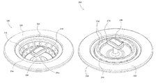
- FIGS. 19-22 illustrate another example of a strainer/stopper 300 in accordance with some embodiments.
- Features of strainer/stopper 300 that are the same or similar to features of strainer/stopper 100 have the same reference numeral increased by 200. Common descriptions are not provided herein.
- the body 304 includes a first set of holes 314 , having a first size, a second set of holes 316 having a second size, and a third set of holes 330 having a third size.
- the first, second, and third set of holes 314 , 316 , 330 are disposed in circumferential rows.
- the first, second, and third sets of holes 314 , 316 , 330 are disposed in circumferential rows with the first set of holes 314 above the second set of holes 316 and the second set of holes 316 above the third set of holes 330 .
- the holes 314 , 316 , 330 may be circular and/or non-circular openings.
- the third set of holes 330 comprises a non-circular opening having a first circumferential section and a second circumferential section coupled by an elongate section (e.g., bone shaped).
- the shape of the holes 314 , 316 , 330 may be configured to provide increased fluid flow when the body 304 is in an extended position and to reduce the necessary force to transition the body 304 to a collapsed position.
- a circumferential ring 332 (or rib) is disposed about an upper portion of the body 304 .
- the circumferential ring 332 may be coupled to the base 302 and/or the body 304 .
- the circumferential ring 332 extends over a portion of the body 304 and may be in contact with and/or spaced apart from the body 304 .
- a complementary circumferential channel 334 is defined by the flange 312 .
- the circumferential channel 334 is sized and configured to receive the circumferential ring 332 therein such that at least a portion of circumferential ring 332 contacts and seals against a wall defining channel 334 while the rest of flange 312 contacts the body 304 to provide a further seal.
- a lower-most portion of circumferential ring 332 contacts the bottom wall defining channel 334 .
- the circumferential ring 332 has a complementary geometry to channel 334 such that a ring 332 fills and contacts the walls defining channel 334 to provide a seal.
- the diameter of flange 312 of strainer/stopper 300 is greater than the diameter of flange 112 of strainer/stopper 100 and/or the flange 212 of strainer/stopper 200 such that the flange contacts and seals against the body 304 .
- the circumferential ring 332 When the body 304 is transitioned to a second collapsed position (see for example, FIGS. 23-24 ), the circumferential ring 332 is positioned within the circumferential channel 334 to further seal the strainer/stopper 300 when in a collapsed position.
- the interface between the circumferential ring 332 and the circumferential channel 334 provides a water tight seal when the body 304 is in the second collapsed position.
- the circumferential ring 332 may comprise any suitable material, such as, for example, stainless steel, aluminum, polymers, plastics, silicone and/or a flexible plastic or polymer, to list only a few possible materials.
- an apparatus comprising a base defining an opening and being formed from a first material and a body coupled to the base and formed from a second material.
- the body defines a plurality of holes and includes an outwardly extending flange.
- the body is configured to be positioned in an extended configuration and a collapsed configuration.
- the flange forms a fluid-tight seal with a portion of the body in the collapsed configuration.
- FIGS. 23-24 illustrate one embodiment of a strainer/stopper 400 .
- Features of strainer/stopper 400 that are the same or similar to features of strainer/stopper 300 have the same reference numeral increased by 100. Common descriptions are not provided herein.
- the body 404 folds about circumferential axis such that strainer/stopper 400 functions as a drain stopper in which fluid cannot pass from the upper side of the stopper 400 to the lower side of the stopper 400 .
- the top of the stem 406 is flush with a top surface of the body 404 .
- the top of the stem 406 and the body 404 are flush.
- the top of the stem 406 may be recessed beneath the top surface of the body 404 .
- an elongated stem 406 is illustrate, it will be appreciated that the stem 406 may have any suitable shape, such as, for example, a rounded shape, a square shape, and/or any other suitable geometric shape.
- FIGS. 25-34 illustrate one embodiment of a strainer/stopper 500 .
- Features of the strainer/stopper 500 that are the same or similar to features of strainer/stopper 400 have the same reference numeral increased by 100. Common descriptions are not provided herein.
- the strainer/stopper 500 includes a flange 518 having at least one rib 536 a. 536 b extending therefrom.
- the at least one rib 536 a, 536 b is sized and configured to be received within a circumferential ring 532 disposed about an upper portion 504 of the strainer/stopper 500 .
- the circumferential ring 532 has an internal diameter sized and configured to receive the flange 512 and the ribs 536 a, 536 b therein.
- the ribs 536 a, 536 b form a fluid-tight seal with the inner surface 540 of the circumferential ring.
- the flange 518 has a circumference less than the internal circumference of the circumferential ring 532 and the ribs 536 a, 536 b have a circumference equal to and/or slightly greater than the internal circumference of the circumferential ring 532 .
- the ribs 536 a , 536 b are deflected out of a plane of the flange 512 when received within the circumferential ring 532 .
- the ribs 536 a, 536 b are positioned within the circumferential ring 532 to further seal the strainer/stopper 500 when in a collapsed position.
- the circumferential ring 532 can comprise any suitable material, such as, for example, stainless steel, aluminum, polymers, plastics, silicone and/or a flexible plastic or polymer, to list only a few possible materials.
- the flange 518 and/or the ribs 536 a, 536 b can comprise any suitable material, such as, for example, stainless steel, aluminum, polymers, plastics, silicone and/or a flexible plastic or polymer, to list only a few possible materials.
- the circumferential ribs 536 a, 536 b provide a friction fit within the inner diameter of the circumferential ring 532 .
- the rings 536 a, 536 b can be forced slightly out-of-plane with respect to the flange 518 when received within the circumferential ring 532 .
- the friction fit between the ribs 536 a, 536 b and the circumferential ring 532 provides a fluid-tight seal.
- the inner surface 540 of the circumferential ring 532 can comprise one or more channels (not shown) sized and configured to receive the ribs 536 a, 536 b therein.
- a drain strainer and stopper in various embodiments, includes a base defining an opening.
- a body is coupled to the base.
- the body defines a plurality of holes and includes a circumferential ring coupled to a first side of the body.
- the body further includes an outwardly extending flange sized and configured to be received within the circumferential ring.
- the body is configured to be positioned in an extended configuration and a collapsed configuration.
- the flange includes at least one outwardly extending circumferential rib that forms a fluid-tight seal with an inner surface 540 of the circumferential ring in the collapsed configuration.
- a method of operating a strainer and stopper comprises placing an outer surface of a body of a strainer and stopper in contact with a surface of a sink such that the body of the drain strainer and stopper is at least partially aligned with a drain of the sink and transitioning the body of the strainer and stopper to one of a collapsed configuration and an extended configuration.
- the collapsed configuration at least one circumferential rib extending from a flange of the strainer and stopper forms a fluid tight seal with an inner surface of a circumferential ring coupled to a body of the strainer and stopper.
- the extended configuration fluid is able to pass through a plurality of holes defined by the body.
- a drain strainer and stopper in various embodiments, includes a base defining an opening.
- the base is formed from a first material.
- a body is coupled to the base and formed from a second material.
- the body defines a plurality of holes and includes a circumferential ring coupled to a first side of the body.
- the body further includes an outwardly extending flange sized and configured to be received within the circumferential ring.
- the body is configured to be positioned in an extended configuration and a collapsed configuration.
- the flange includes at least one outwardly extending circumferential rib that forms a fluid-tight seal with an inner surface of the circumferential ring in the collapsed configuration.
- the body includes at least one area having a reduced thickness to facilitate transitioning from the first extended configuration to the second collapsed configuration.
Abstract
Description
Claims (21)
Priority Applications (1)
| Application Number | Priority Date | Filing Date | Title |
|---|---|---|---|
| US14/973,877 US9790673B2 (en) | 2014-02-28 | 2015-12-18 | Drain strainer and stopper |
Applications Claiming Priority (3)
| Application Number | Priority Date | Filing Date | Title |
|---|---|---|---|
| US201461946182P | 2014-02-28 | 2014-02-28 | |
| PCT/US2015/018075 WO2015131082A1 (en) | 2014-02-28 | 2015-02-27 | Drain strainer and stopper |
| US14/973,877 US9790673B2 (en) | 2014-02-28 | 2015-12-18 | Drain strainer and stopper |
Related Parent Applications (1)
| Application Number | Title | Priority Date | Filing Date |
|---|---|---|---|
| PCT/US2015/018075 Continuation-In-Part WO2015131082A1 (en) | 2014-02-28 | 2015-02-27 | Drain strainer and stopper |
Publications (2)
| Publication Number | Publication Date |
|---|---|
| US20160215485A1 US20160215485A1 (en) | 2016-07-28 |
| US9790673B2 true US9790673B2 (en) | 2017-10-17 |
Family
ID=54009663
Family Applications (1)
| Application Number | Title | Priority Date | Filing Date |
|---|---|---|---|
| US14/973,877 Active 2035-06-04 US9790673B2 (en) | 2014-02-28 | 2015-12-18 | Drain strainer and stopper |
Country Status (2)
| Country | Link |
|---|---|
| US (1) | US9790673B2 (en) |
| WO (1) | WO2015131082A1 (en) |
Cited By (2)
| Publication number | Priority date | Publication date | Assignee | Title |
|---|---|---|---|---|
| US11519161B2 (en) | 2018-03-06 | 2022-12-06 | Pf Waterworks Lp | Drain stopper and strainer |
| US11680397B2 (en) | 2020-06-23 | 2023-06-20 | Pf Waterworks Lp | Kitchen sink drain stopper and strainer |
Families Citing this family (9)
| Publication number | Priority date | Publication date | Assignee | Title |
|---|---|---|---|---|
| WO2015131082A1 (en) | 2014-02-28 | 2015-09-03 | Polder Housewares, Inc. | Drain strainer and stopper |
| USD783782S1 (en) * | 2015-08-28 | 2017-04-11 | Polder Products, Llc | Sink strainer and stopper |
| USD855782S1 (en) * | 2018-03-21 | 2019-08-06 | Juka Innovations Corporation | Kitchen drain strainer |
| CN105926733A (en) * | 2016-05-09 | 2016-09-07 | 无锡昊瑜节能环保设备有限公司 | Telescopic sewer pipeline filter |
| US10273671B2 (en) * | 2016-08-30 | 2019-04-30 | Umbra Llc | Drain cover |
| CN107268736A (en) * | 2017-08-13 | 2017-10-20 | 吴滨 | A kind of lift type water tank discharge filtering device |
| USD919771S1 (en) * | 2017-08-21 | 2021-05-18 | Taizhou Luobang Sanitary Ware Mfg Co., Ltd. | Sink filter device |
| USD855160S1 (en) * | 2019-04-02 | 2019-07-30 | Juka Innovations Corporation | Drain strainer |
| CN112854412A (en) * | 2021-01-15 | 2021-05-28 | 上海翌齐科技有限公司 | Foldable floor drain |
Citations (16)
| Publication number | Priority date | Publication date | Assignee | Title |
|---|---|---|---|---|
| US2643394A (en) * | 1952-07-21 | 1953-06-30 | Kermit P Wood | Combination basket strainer and stopper |
| US2944265A (en) * | 1958-03-10 | 1960-07-12 | Carmichael Bruce | Collapsible sink stopper structure |
| US5915847A (en) | 1998-02-25 | 1999-06-29 | Spears; Cecil J. | Drain stopper with lift mechanism |
| US6067669A (en) | 1999-02-10 | 2000-05-30 | Bathcrest, Inc. | Strainer equipped drain plug assembly |
| US6418568B1 (en) | 1997-02-19 | 2002-07-16 | Raymond Briggs | Eversible stopper/strainer device |
| US6427255B1 (en) | 2001-06-28 | 2002-08-06 | Scott Duncan | Remote controlled stopper device |
| US6484329B1 (en) | 2001-01-24 | 2002-11-26 | Scott Duncan | Bladder-controlled stopper device |
| US20040073992A1 (en) | 2002-10-16 | 2004-04-22 | Husam Saman | Combined strainer and stopper for basin drain |
| US20080149552A1 (en) | 2005-10-21 | 2008-06-26 | Murphy Thomas B | Strainer board with snap-in pop strainer |
| US7678271B2 (en) | 2007-03-22 | 2010-03-16 | Progressive International Corporation | Collapsible colander and bowl |
| US7832027B2 (en) | 2006-10-10 | 2010-11-16 | Helen Of Troy Limited | Flexible sink strainer |
| US8011030B2 (en) | 2008-09-23 | 2011-09-06 | Thank Enterprise Co., Ltd. | Pop-up stopper having draining and straining functions |
| CN102535596A (en) | 2010-12-14 | 2012-07-04 | 美高(集团)实业有限公司 | Fluid discharge strainer valve |
| US8214934B2 (en) | 2007-01-24 | 2012-07-10 | Seamless Sink Llc | Seamless sink drain assembly with disposer/strainer mounting system |
| WO2015131082A1 (en) | 2014-02-28 | 2015-09-03 | Polder Housewares, Inc. | Drain strainer and stopper |
| US9386886B2 (en) * | 2014-01-31 | 2016-07-12 | Robinson Home Products Inc. | Over sink kitchen work station |
-
2015
- 2015-02-27 WO PCT/US2015/018075 patent/WO2015131082A1/en active Application Filing
- 2015-12-18 US US14/973,877 patent/US9790673B2/en active Active
Patent Citations (18)
| Publication number | Priority date | Publication date | Assignee | Title |
|---|---|---|---|---|
| US2643394A (en) * | 1952-07-21 | 1953-06-30 | Kermit P Wood | Combination basket strainer and stopper |
| US2944265A (en) * | 1958-03-10 | 1960-07-12 | Carmichael Bruce | Collapsible sink stopper structure |
| US6418568B1 (en) | 1997-02-19 | 2002-07-16 | Raymond Briggs | Eversible stopper/strainer device |
| US5915847A (en) | 1998-02-25 | 1999-06-29 | Spears; Cecil J. | Drain stopper with lift mechanism |
| US6067669A (en) | 1999-02-10 | 2000-05-30 | Bathcrest, Inc. | Strainer equipped drain plug assembly |
| US6484329B1 (en) | 2001-01-24 | 2002-11-26 | Scott Duncan | Bladder-controlled stopper device |
| US6427255B1 (en) | 2001-06-28 | 2002-08-06 | Scott Duncan | Remote controlled stopper device |
| US20040073992A1 (en) | 2002-10-16 | 2004-04-22 | Husam Saman | Combined strainer and stopper for basin drain |
| US20080149552A1 (en) | 2005-10-21 | 2008-06-26 | Murphy Thomas B | Strainer board with snap-in pop strainer |
| US7832027B2 (en) | 2006-10-10 | 2010-11-16 | Helen Of Troy Limited | Flexible sink strainer |
| US8117685B2 (en) | 2006-10-10 | 2012-02-21 | Helen Of Troy Limited | Flexible sink strainer |
| US8171574B2 (en) * | 2006-10-10 | 2012-05-08 | Helen Of Troy Limited | Flexible sink strainer |
| US8214934B2 (en) | 2007-01-24 | 2012-07-10 | Seamless Sink Llc | Seamless sink drain assembly with disposer/strainer mounting system |
| US7678271B2 (en) | 2007-03-22 | 2010-03-16 | Progressive International Corporation | Collapsible colander and bowl |
| US8011030B2 (en) | 2008-09-23 | 2011-09-06 | Thank Enterprise Co., Ltd. | Pop-up stopper having draining and straining functions |
| CN102535596A (en) | 2010-12-14 | 2012-07-04 | 美高(集团)实业有限公司 | Fluid discharge strainer valve |
| US9386886B2 (en) * | 2014-01-31 | 2016-07-12 | Robinson Home Products Inc. | Over sink kitchen work station |
| WO2015131082A1 (en) | 2014-02-28 | 2015-09-03 | Polder Housewares, Inc. | Drain strainer and stopper |
Non-Patent Citations (3)
| Title |
|---|
| "Collapsible Stopper & Strainer", Tovolo, ICI USA, LLC, 2013 Catalog, http://www.tovolo.com/product/collapsible-stopper-and-strainer-2/. |
| "Silicone Sink Strainer & Stopper", OXO Good Grips Silicone Sink Strainer and Stopper, Dec. 10, 2013, https://www.oxo.com/silicone-sink-strainer-with-stopper. |
| International Search Report/Written Opinion dated May 29, 2015 in counterpart Intl. Patent Application No. PCT/US2015/018075. |
Cited By (2)
| Publication number | Priority date | Publication date | Assignee | Title |
|---|---|---|---|---|
| US11519161B2 (en) | 2018-03-06 | 2022-12-06 | Pf Waterworks Lp | Drain stopper and strainer |
| US11680397B2 (en) | 2020-06-23 | 2023-06-20 | Pf Waterworks Lp | Kitchen sink drain stopper and strainer |
Also Published As
| Publication number | Publication date |
|---|---|
| US20160215485A1 (en) | 2016-07-28 |
| WO2015131082A1 (en) | 2015-09-03 |
Similar Documents
| Publication | Publication Date | Title |
|---|---|---|
| US9790673B2 (en) | Drain strainer and stopper | |
| USD878156S1 (en) | Beverage bottle | |
| USD882817S1 (en) | Sample container | |
| USD812430S1 (en) | Drinking vessel | |
| USD810884S1 (en) | Faucet handle | |
| USD792759S1 (en) | Tray | |
| US20220331205A1 (en) | Teat for an infant feeding bottle | |
| US9752306B2 (en) | Waste strainer | |
| USD811545S1 (en) | Faucet handle | |
| USD839996S1 (en) | Faucet handle | |
| USD846708S1 (en) | Faucet handle | |
| EP1958883A1 (en) | Dispensing valve and a container for holding fluid, provided with such a dispensing valve | |
| USD885660S1 (en) | Soap | |
| USD812197S1 (en) | Faucet handle | |
| USD839391S1 (en) | Faucet handle | |
| USD851730S1 (en) | Faucet handle | |
| USD810881S1 (en) | Faucet escutcheon | |
| USD878523S1 (en) | Faucet handle | |
| US20180320349A1 (en) | External hair strainer | |
| USD770597S1 (en) | Faucet handle | |
| USD811542S1 (en) | Faucet handle | |
| WO2018067009A8 (en) | A capsule, a system for preparing a potable beverage from such a capsule and use of such a capsule in a beverage preparation device | |
| US10577785B2 (en) | External hair strainer | |
| USD818325S1 (en) | Pail | |
| US20120036624A1 (en) | Drain insert |
Legal Events
| Date | Code | Title | Description |
|---|---|---|---|
| AS | Assignment |
Owner name: POLDER HOUSEWARES, INC., CONNECTICUT Free format text: ASSIGNMENT OF ASSIGNORS INTEREST;ASSIGNORS:SCOTT, GEORGE CALVIN;PEDROS, ROBERTO;COOPER, KERRY;SIGNING DATES FROM 20151221 TO 20151222;REEL/FRAME:037362/0797 |
|
| AS | Assignment |
Owner name: PEOPLE'S UNITED BANK, NATIONAL ASSOCIATION, CONNEC Free format text: SECURITY AGREEMENT;ASSIGNOR:POLDER PRODUCTS, LLC;REEL/FRAME:037484/0889 Effective date: 20160111 Owner name: POLDER PRODUCTS, LLC, CONNECTICUT Free format text: ASSIGNMENT OF ASSIGNORS INTEREST;ASSIGNORS:POLDER INTERNATIONAL, INC.;POLDER HOUSEWARES, INC.;POLDER INDUSTRIES, INC.;REEL/FRAME:037462/0172 Effective date: 20160111 Owner name: ADVANTAGE CAPITAL CONNECTICUT PARTNERS I, LIMITED Free format text: INTELLECTUAL PROPERTY SECURITY AGREEMENT;ASSIGNOR:POLDER PRODUCTS, LLC;REEL/FRAME:037485/0259 Effective date: 20160111 |
|
| STCF | Information on status: patent grant |
Free format text: PATENTED CASE |
|
| AS | Assignment |
Owner name: FIFTH THIRD BANK, NATIONAL ASSOCIATION, ILLINOIS Free format text: SECURITY AGREEMENT;ASSIGNOR:POLDER PRODUCTS, LLC;REEL/FRAME:054976/0023 Effective date: 20201222 Owner name: POLDER PRODUCTS, LLC, CONNECTICUT Free format text: RELEASE OF INTELLECTUAL PROPERTY SECURITY INTEREST;ASSIGNOR:PEOPLE'S UNITED BANK, NATIONAL ASSOCIATION;REEL/FRAME:054976/0055 Effective date: 20201218 |
|
| MAFP | Maintenance fee payment |
Free format text: PAYMENT OF MAINTENANCE FEE, 4TH YR, SMALL ENTITY (ORIGINAL EVENT CODE: M2551); ENTITY STATUS OF PATENT OWNER: SMALL ENTITY Year of fee payment: 4 |
|
| AS | Assignment |
Owner name: ADVANTAGE CAPITAL CONNECTICUT PARTNERS I, LIMITED PARTNERSHIP, CONNECTICUT Free format text: GRANT OF SECURITY INTEREST IN TRADEMARKS AND PATENTS;ASSIGNOR:POLDER PRODUCTS, LLC;REEL/FRAME:055973/0778 Effective date: 20210408 |
|
| AS | Assignment |
Owner name: POLDER PRODUCTS, LLC, CONNECTICUT Free format text: RELEASE AND REASSIGNMENT OF PATENTS;ASSIGNOR:ADVANTAGE CAPITAL CONNECTICUT PARTNERS I, LIMITED PARTNERSHIP;REEL/FRAME:065086/0069 Effective date: 20230929 |