US9786941B2 - Metal ionophores in PEM membranes - Google Patents
Metal ionophores in PEM membranes Download PDFInfo
- Publication number
- US9786941B2 US9786941B2 US13/611,694 US201213611694A US9786941B2 US 9786941 B2 US9786941 B2 US 9786941B2 US 201213611694 A US201213611694 A US 201213611694A US 9786941 B2 US9786941 B2 US 9786941B2
- Authority
- US
- United States
- Prior art keywords
- polymer
- electrode assembly
- membrane electrode
- membrane
- added
- Prior art date
- Legal status (The legal status is an assumption and is not a legal conclusion. Google has not performed a legal analysis and makes no representation as to the accuracy of the status listed.)
- Active, expires
Links
- 0 CCC1C*CC1 Chemical compound CCC1C*CC1 0.000 description 8
- ATEVKNNUOGFZLU-UHFFFAOYSA-N C=CC1=CC=C(COCC2=CC=C3OCCOCCOCCOCCOC3=C2)C=C1 Chemical compound C=CC1=CC=C(COCC2=CC=C3OCCOCCOCCOCCOC3=C2)C=C1 ATEVKNNUOGFZLU-UHFFFAOYSA-N 0.000 description 2
- MQDSEPJXSZVIEB-UHFFFAOYSA-N C=CC1=CC=C2OCCN3CCOCCOCCN(CCOCCOCC3)CCOC2=C1 Chemical compound C=CC1=CC=C2OCCN3CCOCCOCCN(CCOCCOCC3)CCOC2=C1 MQDSEPJXSZVIEB-UHFFFAOYSA-N 0.000 description 2
- SMJWTJPWCKITEE-UHFFFAOYSA-N CC(C)(C)CC1COCCN2CCOCCOCCN(CCOCC2)CCO1.CC(C)(C)N1CCOCCNCCOCCOCC1.CC(C)(C)N1CCOCCOCCNCCOCCOCC1.CC(C)(C)N1CCOCCOCCOCCOCCOCC1.CC(C)(C)OCC1COCCN2CCOCCOCCN(CCOCC2)CCO1.CC(C)(C)OCC1COCCN2CCOCCOCCN(CCOCCOCC2)CCO1 Chemical compound CC(C)(C)CC1COCCN2CCOCCOCCN(CCOCC2)CCO1.CC(C)(C)N1CCOCCNCCOCCOCC1.CC(C)(C)N1CCOCCOCCNCCOCCOCC1.CC(C)(C)N1CCOCCOCCOCCOCCOCC1.CC(C)(C)OCC1COCCN2CCOCCOCCN(CCOCC2)CCO1.CC(C)(C)OCC1COCCN2CCOCCOCCN(CCOCCOCC2)CCO1 SMJWTJPWCKITEE-UHFFFAOYSA-N 0.000 description 2
- VJDQXHYRLPDCSE-UHFFFAOYSA-N C.C.C.CC1CC(C2=CC=CC(O)=C2)CC(C2=CC=CC(O)=C2)CC(C2=CC=CC(O)=C2)CC(C2=CC=CC(O)=C2)CC(C)C2=CC=C(C=C2)C(C)C(C2=CC=CC(O)=C2)CC(C2=CC=C(O)C=C2)CC(C2=CC=CC(O)=C2)CC(C2=CC=CC(O)=C2)CC(C2=CC=CC(O)=C2)CC(C2=CC=C(O)C=C2)CC(C)C2=CC=C1C=C2.O.O.O.O.O.O.O.O.O.O.O.O.O.O.O.O.O.O.O.O.O.O.O.O.O.O.O.O.O.O.O.O.O.O.O.O.O.O.O Chemical compound C.C.C.CC1CC(C2=CC=CC(O)=C2)CC(C2=CC=CC(O)=C2)CC(C2=CC=CC(O)=C2)CC(C2=CC=CC(O)=C2)CC(C)C2=CC=C(C=C2)C(C)C(C2=CC=CC(O)=C2)CC(C2=CC=C(O)C=C2)CC(C2=CC=CC(O)=C2)CC(C2=CC=CC(O)=C2)CC(C2=CC=CC(O)=C2)CC(C2=CC=C(O)C=C2)CC(C)C2=CC=C1C=C2.O.O.O.O.O.O.O.O.O.O.O.O.O.O.O.O.O.O.O.O.O.O.O.O.O.O.O.O.O.O.O.O.O.O.O.O.O.O.O VJDQXHYRLPDCSE-UHFFFAOYSA-N 0.000 description 1
- RXGFJGSZTZDYFM-UHFFFAOYSA-N C.C.CC1CC(C2=CC=C3OCCOCCOCCOCCOCCOC3=C2)CC(C2=CC=C3OCCOCCOCCOCCOCCOC3=C2)CC(C2=CC=C3OCCOCCOCCOCCOCCOC3=C2)CC(C2=C\C=C3\OCCOCCOCCOCCOCCO\C3=C\2)CC(C)C2=CC=C(C=C2)C(C)C(C2=C/C=C3/OCCOCCOCCOCCOCCO/C3=C\2)CC(C2=CC=C3OCCOCCOCCOCCOCCOC3=C2)CC(C2=CC=C3OCCOCCOCCOCCOCCOC3=C2)CC(C2=C\C=C3\OCCOCCOCCOCCOCCO\C3=C\2)CC(C2=C/C=C3\OCCOCCOCCOCCOCCO\C3=C\2)CC(C2=CC=C3OCCOCCOCCOCCOCCOC3=C2)CC(C)C2=CC=C1C=C2 Chemical compound C.C.CC1CC(C2=CC=C3OCCOCCOCCOCCOCCOC3=C2)CC(C2=CC=C3OCCOCCOCCOCCOCCOC3=C2)CC(C2=CC=C3OCCOCCOCCOCCOCCOC3=C2)CC(C2=C\C=C3\OCCOCCOCCOCCOCCO\C3=C\2)CC(C)C2=CC=C(C=C2)C(C)C(C2=C/C=C3/OCCOCCOCCOCCOCCO/C3=C\2)CC(C2=CC=C3OCCOCCOCCOCCOCCOC3=C2)CC(C2=CC=C3OCCOCCOCCOCCOCCOC3=C2)CC(C2=C\C=C3\OCCOCCOCCOCCOCCO\C3=C\2)CC(C2=C/C=C3\OCCOCCOCCOCCOCCO\C3=C\2)CC(C2=CC=C3OCCOCCOCCOCCOCCOC3=C2)CC(C)C2=CC=C1C=C2 RXGFJGSZTZDYFM-UHFFFAOYSA-N 0.000 description 1
- JBXMVSFLLGHQTG-UHFFFAOYSA-N C.C.CCC(C)C Chemical compound C.C.CCC(C)C JBXMVSFLLGHQTG-UHFFFAOYSA-N 0.000 description 1
- CGIDVJJMZNVVJL-UHFFFAOYSA-N C1=CC=C2OCCOC3=C(C=CC=C3)OCCOCCOC2=C1.C1=CC=C2OCCOCCOC3=C(C=CC=C3)OCCOCCOC2=C1.C1=CC=C2OCCOCCOCCOCCOCCOC2=C1.CC(C)(C)C.CC(C)(C)C.CC(C)(C)C.CC(C)(C)C1=CC=C2OCCN3CCOCCOCCN(CCOCCOCC3)CCOC2=C1.CC(C)(C)C1COCCOCCOCCOCCO1.CC(C)(C)C1COCCOCCOCCOCCOCCO1.CC(C)(C)N1CCOCCOCCOCCOCC1 Chemical compound C1=CC=C2OCCOC3=C(C=CC=C3)OCCOCCOC2=C1.C1=CC=C2OCCOCCOC3=C(C=CC=C3)OCCOCCOC2=C1.C1=CC=C2OCCOCCOCCOCCOCCOC2=C1.CC(C)(C)C.CC(C)(C)C.CC(C)(C)C.CC(C)(C)C1=CC=C2OCCN3CCOCCOCCN(CCOCCOCC3)CCOC2=C1.CC(C)(C)C1COCCOCCOCCOCCO1.CC(C)(C)C1COCCOCCOCCOCCOCCO1.CC(C)(C)N1CCOCCOCCOCCOCC1 CGIDVJJMZNVVJL-UHFFFAOYSA-N 0.000 description 1
- KDUCTAGFESJBHE-UHFFFAOYSA-N C1COCCNCCOCCOCCN1.C=CC1=CC=C(CN2CCOCCOCCOCCOCC2)C=C1 Chemical compound C1COCCNCCOCCOCCN1.C=CC1=CC=C(CN2CCOCCOCCOCCOCC2)C=C1 KDUCTAGFESJBHE-UHFFFAOYSA-N 0.000 description 1
- ICCAFPLHNYRPEQ-UHFFFAOYSA-N C=C(=C)(OC1=CC=C(C2=CC=C(OC3(F)C(C)(F)C(F)(F)C3(F)F)C(C(F)(F)C(F)(F)OC(F)(F)C(F)(F)S(=O)(=O)O)=C2)C=C1C(F)(F)C(F)(F)OC(F)(F)C(F)(F)S(=O)(=O)O)C1(F)C(F)(F)C(F)(F)C1(F)OC1=CC=C(C(C2=CC=C(OC)C=C2)(C(F)(F)F)C(F)(F)F)C=C1 Chemical compound C=C(=C)(OC1=CC=C(C2=CC=C(OC3(F)C(C)(F)C(F)(F)C3(F)F)C(C(F)(F)C(F)(F)OC(F)(F)C(F)(F)S(=O)(=O)O)=C2)C=C1C(F)(F)C(F)(F)OC(F)(F)C(F)(F)S(=O)(=O)O)C1(F)C(F)(F)C(F)(F)C1(F)OC1=CC=C(C(C2=CC=C(OC)C=C2)(C(F)(F)F)C(F)(F)F)C=C1 ICCAFPLHNYRPEQ-UHFFFAOYSA-N 0.000 description 1
- ZKMGXQMDGGVGJU-UHFFFAOYSA-N C=CC1=CC=C2OCCN3CCOCCOCCN(CCOCC3)CCOC2=C1.C=CC1=CC=C2OCCN3CCOCCOCCN(CCOCCOCC3)CCOC2=C1 Chemical compound C=CC1=CC=C2OCCN3CCOCCOCCN(CCOCC3)CCOC2=C1.C=CC1=CC=C2OCCN3CCOCCOCCN(CCOCCOCC3)CCOC2=C1 ZKMGXQMDGGVGJU-UHFFFAOYSA-N 0.000 description 1
- ZZFCDIHBQRUIOD-UHFFFAOYSA-N C=CC1=CC=C2OCCN3CCOCCOCCN(CCOCCOCC3)CCOC2=C1.CC(=O)C1=CC=C(O)C(O)=C1 Chemical compound C=CC1=CC=C2OCCN3CCOCCOCCN(CCOCCOCC3)CCOC2=C1.CC(=O)C1=CC=C(O)C(O)=C1 ZZFCDIHBQRUIOD-UHFFFAOYSA-N 0.000 description 1
- ZAGUIKUTRQQXFR-UHFFFAOYSA-N C=CC1=CC=C2OCCOC3=C(C=C(C=C)C=C3)OCCOC2=C1 Chemical compound C=CC1=CC=C2OCCOC3=C(C=C(C=C)C=C3)OCCOC2=C1 ZAGUIKUTRQQXFR-UHFFFAOYSA-N 0.000 description 1
- MYDDYOANJGGJLA-UHFFFAOYSA-N C=CC1=CC=C2OCCOCCOCCOCCOC2=C1.C=CC1=CC=C2OCCOCCOCCOCCOCCOC2=C1 Chemical compound C=CC1=CC=C2OCCOCCOCCOCCOC2=C1.C=CC1=CC=C2OCCOCCOCCOCCOCCOC2=C1 MYDDYOANJGGJLA-UHFFFAOYSA-N 0.000 description 1
- CGZSAEJNWTUFOM-UHFFFAOYSA-N C=CC1=CC=C2OCCOCCOCCOCCOC3=C(C=C(C=C)C=C3)OCCOCCOCCOCCOC2=C1 Chemical compound C=CC1=CC=C2OCCOCCOCCOCCOC3=C(C=C(C=C)C=C3)OCCOCCOCCOCCOC2=C1 CGZSAEJNWTUFOM-UHFFFAOYSA-N 0.000 description 1
- JNNYRNNTFKYSSO-UHFFFAOYSA-N C=CC1=CC=C2OCCOCCOCCOCCOC3=C(C=C(C=C)C=C3)OCCOCCOCCOCCOC2=C1.C=CC1COCCN2CCOCCOCCN(CCOCCOCC2)CCO1 Chemical compound C=CC1=CC=C2OCCOCCOCCOCCOC3=C(C=C(C=C)C=C3)OCCOCCOCCOCCOC2=C1.C=CC1COCCN2CCOCCOCCN(CCOCCOCC2)CCO1 JNNYRNNTFKYSSO-UHFFFAOYSA-N 0.000 description 1
- INSLQRDXNHLHMF-UHFFFAOYSA-N CC(C)(C)C1=CC=C(CN2CCOCCOCCOCCOCC2)C=C1.CC(C)(C)C1=CC=C(CN2CCOCCOCCOCCOCCOCC2)C=C1 Chemical compound CC(C)(C)C1=CC=C(CN2CCOCCOCCOCCOCC2)C=C1.CC(C)(C)C1=CC=C(CN2CCOCCOCCOCCOCCOCC2)C=C1 INSLQRDXNHLHMF-UHFFFAOYSA-N 0.000 description 1
- WVPKXZXPPNENRX-UHFFFAOYSA-N CC(C)(C)C1=CC=C(CN2CCOCCOCCOCCOCC2)C=C1.CC(C)(C)C1=CC=C(CN2CCOCCOCCOCCOCCOCC2)C=C1.CC(C)(C)C1=CC=C(COCC2COCCOCCOCCOCCOCCO2)C=C1.CC(C)(C)C1=CC=C(COCO2CCOCCOCCOCCOCC2)C=C1 Chemical compound CC(C)(C)C1=CC=C(CN2CCOCCOCCOCCOCC2)C=C1.CC(C)(C)C1=CC=C(CN2CCOCCOCCOCCOCCOCC2)C=C1.CC(C)(C)C1=CC=C(COCC2COCCOCCOCCOCCOCCO2)C=C1.CC(C)(C)C1=CC=C(COCO2CCOCCOCCOCCOCC2)C=C1 WVPKXZXPPNENRX-UHFFFAOYSA-N 0.000 description 1
- RJVHSKLLTZBCEQ-UHFFFAOYSA-N CC(C)(C)C1=CC=C2OCCN3CCOCCOCCN(CCOCC3)CCOC2=C1.CC(C)(C)C1=CC=C2OCCN3CCOCCOCCN(CCOCC3)CCOC2=C1 Chemical compound CC(C)(C)C1=CC=C2OCCN3CCOCCOCCN(CCOCC3)CCOC2=C1.CC(C)(C)C1=CC=C2OCCN3CCOCCOCCN(CCOCC3)CCOC2=C1 RJVHSKLLTZBCEQ-UHFFFAOYSA-N 0.000 description 1
- APZVTBDSYKTQRC-UHFFFAOYSA-N CC(C)(C)C1=CC=C2OCCN3CCOCCOCCN(CCOCC3)CCOC2=C1.CC(C)(C)C1=CC=C2OCCN3CCOCCOCCN(CCOCC3)CCOC2=C1.CC(C)(C)C1=CC=C2OCCOCCOCCOCCOC2=C1.CC(C)(C)C1=CC=C2OCCOCCOCCOCCOCCOC2=C1.CC(C)(C)OCC1COCCOCCOCCOCCO1.CC(C)(C)OCC1COCCOCCOCCOCCOCCO1.CC(C)(C)OCC1COCCOCCOCCOCCOCCO1 Chemical compound CC(C)(C)C1=CC=C2OCCN3CCOCCOCCN(CCOCC3)CCOC2=C1.CC(C)(C)C1=CC=C2OCCN3CCOCCOCCN(CCOCC3)CCOC2=C1.CC(C)(C)C1=CC=C2OCCOCCOCCOCCOC2=C1.CC(C)(C)C1=CC=C2OCCOCCOCCOCCOCCOC2=C1.CC(C)(C)OCC1COCCOCCOCCOCCO1.CC(C)(C)OCC1COCCOCCOCCOCCOCCO1.CC(C)(C)OCC1COCCOCCOCCOCCOCCO1 APZVTBDSYKTQRC-UHFFFAOYSA-N 0.000 description 1
- OIGOOZJYMIGGBR-UHFFFAOYSA-N CC(C)(C)C1=CC=C2OCCN3CCOCCOCCN(CCOCCOCC3)CCOC2=C1.CC(C)(C)N1CCOCCOCCOCCOCC1 Chemical compound CC(C)(C)C1=CC=C2OCCN3CCOCCOCCN(CCOCCOCC3)CCOC2=C1.CC(C)(C)N1CCOCCOCCOCCOCC1 OIGOOZJYMIGGBR-UHFFFAOYSA-N 0.000 description 1
- QWWVHNYNDUHATO-UHFFFAOYSA-N CC(O)C1=CC=C2OCCOCCOCCOCCOC3=C(C=C(C(C)O)C=C3)OCCOCCOCCOCCOC2=C1 Chemical compound CC(O)C1=CC=C2OCCOCCOCCOCCOC3=C(C=C(C(C)O)C=C3)OCCOCCOCCOCCOC2=C1 QWWVHNYNDUHATO-UHFFFAOYSA-N 0.000 description 1
- ZABDVOBLDBVVLL-UHFFFAOYSA-N CC1(F)C(C)(F)C(F)(F)C1(C)F.CC1(F)C(C)(F)C(F)(F)C1(F)F Chemical compound CC1(F)C(C)(F)C(F)(F)C1(C)F.CC1(F)C(C)(F)C(F)(F)C1(F)F ZABDVOBLDBVVLL-UHFFFAOYSA-N 0.000 description 1
- UBFWKLUJZNYXAL-UHFFFAOYSA-N CC1(F)C(C)(F)C(F)(F)C1(F)F.CC1(F)C(F)(F)C(C)(F)C1(F)F Chemical compound CC1(F)C(C)(F)C(F)(F)C1(F)F.CC1(F)C(F)(F)C(C)(F)C1(F)F UBFWKLUJZNYXAL-UHFFFAOYSA-N 0.000 description 1
- AHNUDGLKXOLGIS-UHFFFAOYSA-N COC(c(cc1OCC(Cl)=O)ccc1OCC(Cl)=O)OC Chemical compound COC(c(cc1OCC(Cl)=O)ccc1OCC(Cl)=O)OC AHNUDGLKXOLGIS-UHFFFAOYSA-N 0.000 description 1
- XWRKEAFJPNEOMK-UHFFFAOYSA-N OCC1COCCN2CCOCCOCCN(CCOCCOCC2)CCO1 Chemical compound OCC1COCCN2CCOCCOCCN(CCOCCOCC2)CCO1 XWRKEAFJPNEOMK-UHFFFAOYSA-N 0.000 description 1
- JZFIYRLQCIMRCY-UHFFFAOYSA-N OCC1COCCN2CCOCCOCCN(CCOCCOCC2)CCO1.OCC1COCCOCCOCCOCCO1.OCC1COCCOCCOCCOCCOCCO1 Chemical compound OCC1COCCN2CCOCCOCCN(CCOCCOCC2)CCO1.OCC1COCCOCCOCCOCCO1.OCC1COCCOCCOCCOCCOCCO1 JZFIYRLQCIMRCY-UHFFFAOYSA-N 0.000 description 1
- UNMGNKFTTQYBMB-UHFFFAOYSA-N [H]C(=O)C1=CC(OCC(=O)O)=C(OCC(=O)O)C=C1 Chemical compound [H]C(=O)C1=CC(OCC(=O)O)=C(OCC(=O)O)C=C1 UNMGNKFTTQYBMB-UHFFFAOYSA-N 0.000 description 1
- AQFCLLOWMKPKPG-UHFFFAOYSA-N [H]C(=O)C1=CC=C2OCCOCCOCCOCCOC2=C1.[H]C(=O)C1=CC=C2OCCOCCOCCOCCOC3=C(C=C(C([H])=O)C=C3)OCCOCCOCCOCCOC2=C1 Chemical compound [H]C(=O)C1=CC=C2OCCOCCOCCOCCOC2=C1.[H]C(=O)C1=CC=C2OCCOCCOCCOCCOC3=C(C=C(C([H])=O)C=C3)OCCOCCOCCOCCOC2=C1 AQFCLLOWMKPKPG-UHFFFAOYSA-N 0.000 description 1
- DOMJCFQGDMISJY-UHFFFAOYSA-N [H]C(=O)C1=CC=C2OCCOCCOCCOCCOC3=C(C=C(C([H])=O)C=C3)OCCOCCOCCOCCOC2=C1 Chemical compound [H]C(=O)C1=CC=C2OCCOCCOCCOCCOC3=C(C=C(C([H])=O)C=C3)OCCOCCOCCOCCOC2=C1 DOMJCFQGDMISJY-UHFFFAOYSA-N 0.000 description 1
- JISMFISXMMESFR-UHFFFAOYSA-N [H]C(CO)(OC)C1=CC(OCC(=O)Cl)=C(OCC(=O)Cl)C=C1 Chemical compound [H]C(CO)(OC)C1=CC(OCC(=O)Cl)=C(OCC(=O)Cl)C=C1 JISMFISXMMESFR-UHFFFAOYSA-N 0.000 description 1
- VNYJIQDPRUMXQL-UHFFFAOYSA-N [H]C(CO)(OC)C1=CC(OCC(=O)OC)=C(OCC(=O)OC)C=C1 Chemical compound [H]C(CO)(OC)C1=CC(OCC(=O)OC)=C(OCC(=O)OC)C=C1 VNYJIQDPRUMXQL-UHFFFAOYSA-N 0.000 description 1
Images


Classifications
-
- H—ELECTRICITY
- H01—ELECTRIC ELEMENTS
- H01M—PROCESSES OR MEANS, e.g. BATTERIES, FOR THE DIRECT CONVERSION OF CHEMICAL ENERGY INTO ELECTRICAL ENERGY
- H01M8/00—Fuel cells; Manufacture thereof
- H01M8/10—Fuel cells with solid electrolytes
- H01M8/1004—Fuel cells with solid electrolytes characterised by membrane-electrode assemblies [MEA]
-
- C—CHEMISTRY; METALLURGY
- C08—ORGANIC MACROMOLECULAR COMPOUNDS; THEIR PREPARATION OR CHEMICAL WORKING-UP; COMPOSITIONS BASED THEREON
- C08J—WORKING-UP; GENERAL PROCESSES OF COMPOUNDING; AFTER-TREATMENT NOT COVERED BY SUBCLASSES C08B, C08C, C08F, C08G or C08H
- C08J5/00—Manufacture of articles or shaped materials containing macromolecular substances
- C08J5/20—Manufacture of shaped structures of ion-exchange resins
- C08J5/22—Films, membranes or diaphragms
- C08J5/2206—Films, membranes or diaphragms based on organic and/or inorganic macromolecular compounds
- C08J5/2218—Synthetic macromolecular compounds
-
- H—ELECTRICITY
- H01—ELECTRIC ELEMENTS
- H01M—PROCESSES OR MEANS, e.g. BATTERIES, FOR THE DIRECT CONVERSION OF CHEMICAL ENERGY INTO ELECTRICAL ENERGY
- H01M8/00—Fuel cells; Manufacture thereof
- H01M8/10—Fuel cells with solid electrolytes
- H01M8/1016—Fuel cells with solid electrolytes characterised by the electrolyte material
- H01M8/1018—Polymeric electrolyte materials
- H01M8/102—Polymeric electrolyte materials characterised by the chemical structure of the main chain of the ion-conducting polymer
- H01M8/1023—Polymeric electrolyte materials characterised by the chemical structure of the main chain of the ion-conducting polymer having only carbon, e.g. polyarylenes, polystyrenes or polybutadiene-styrenes
-
- H—ELECTRICITY
- H01—ELECTRIC ELEMENTS
- H01M—PROCESSES OR MEANS, e.g. BATTERIES, FOR THE DIRECT CONVERSION OF CHEMICAL ENERGY INTO ELECTRICAL ENERGY
- H01M8/00—Fuel cells; Manufacture thereof
- H01M8/10—Fuel cells with solid electrolytes
- H01M8/1016—Fuel cells with solid electrolytes characterised by the electrolyte material
- H01M8/1018—Polymeric electrolyte materials
- H01M8/1039—Polymeric electrolyte materials halogenated, e.g. sulfonated polyvinylidene fluorides
-
- H—ELECTRICITY
- H01—ELECTRIC ELEMENTS
- H01M—PROCESSES OR MEANS, e.g. BATTERIES, FOR THE DIRECT CONVERSION OF CHEMICAL ENERGY INTO ELECTRICAL ENERGY
- H01M8/00—Fuel cells; Manufacture thereof
- H01M8/10—Fuel cells with solid electrolytes
- H01M8/1016—Fuel cells with solid electrolytes characterised by the electrolyte material
- H01M8/1018—Polymeric electrolyte materials
- H01M8/1041—Polymer electrolyte composites, mixtures or blends
- H01M8/1044—Mixtures of polymers, of which at least one is ionically conductive
-
- H—ELECTRICITY
- H01—ELECTRIC ELEMENTS
- H01M—PROCESSES OR MEANS, e.g. BATTERIES, FOR THE DIRECT CONVERSION OF CHEMICAL ENERGY INTO ELECTRICAL ENERGY
- H01M8/00—Fuel cells; Manufacture thereof
- H01M8/10—Fuel cells with solid electrolytes
- H01M8/1016—Fuel cells with solid electrolytes characterised by the electrolyte material
- H01M8/1018—Polymeric electrolyte materials
- H01M8/1069—Polymeric electrolyte materials characterised by the manufacturing processes
- H01M8/1081—Polymeric electrolyte materials characterised by the manufacturing processes starting from solutions, dispersions or slurries exclusively of polymers
-
- C—CHEMISTRY; METALLURGY
- C08—ORGANIC MACROMOLECULAR COMPOUNDS; THEIR PREPARATION OR CHEMICAL WORKING-UP; COMPOSITIONS BASED THEREON
- C08J—WORKING-UP; GENERAL PROCESSES OF COMPOUNDING; AFTER-TREATMENT NOT COVERED BY SUBCLASSES C08B, C08C, C08F, C08G or C08H
- C08J2371/00—Characterised by the use of polyethers obtained by reactions forming an ether link in the main chain; Derivatives of such polymers
- C08J2371/08—Polyethers derived from hydroxy compounds or from their metallic derivatives
- C08J2371/10—Polyethers derived from hydroxy compounds or from their metallic derivatives from phenols
- C08J2371/12—Polyphenylene oxides
-
- Y—GENERAL TAGGING OF NEW TECHNOLOGICAL DEVELOPMENTS; GENERAL TAGGING OF CROSS-SECTIONAL TECHNOLOGIES SPANNING OVER SEVERAL SECTIONS OF THE IPC; TECHNICAL SUBJECTS COVERED BY FORMER USPC CROSS-REFERENCE ART COLLECTIONS [XRACs] AND DIGESTS
- Y02—TECHNOLOGIES OR APPLICATIONS FOR MITIGATION OR ADAPTATION AGAINST CLIMATE CHANGE
- Y02E—REDUCTION OF GREENHOUSE GAS [GHG] EMISSIONS, RELATED TO ENERGY GENERATION, TRANSMISSION OR DISTRIBUTION
- Y02E60/00—Enabling technologies; Technologies with a potential or indirect contribution to GHG emissions mitigation
- Y02E60/30—Hydrogen technology
- Y02E60/50—Fuel cells
-
- Y—GENERAL TAGGING OF NEW TECHNOLOGICAL DEVELOPMENTS; GENERAL TAGGING OF CROSS-SECTIONAL TECHNOLOGIES SPANNING OVER SEVERAL SECTIONS OF THE IPC; TECHNICAL SUBJECTS COVERED BY FORMER USPC CROSS-REFERENCE ART COLLECTIONS [XRACs] AND DIGESTS
- Y02—TECHNOLOGIES OR APPLICATIONS FOR MITIGATION OR ADAPTATION AGAINST CLIMATE CHANGE
- Y02P—CLIMATE CHANGE MITIGATION TECHNOLOGIES IN THE PRODUCTION OR PROCESSING OF GOODS
- Y02P70/00—Climate change mitigation technologies in the production process for final industrial or consumer products
- Y02P70/50—Manufacturing or production processes characterised by the final manufactured product
-
- Y02P70/56—
Definitions
- the present invention relates to proton exchange membranes for fuel cells with improved stability.
- Fuel cells are used as an electrical power source in many applications. In particular, fuel cells are proposed for use in automobiles to replace internal combustion engines.
- a commonly used fuel cell design uses a solid polymer electrolyte (“SPE”) membrane or proton exchange membrane (“PEM”) to provide ion transport between the anode and cathode.
- SPE solid polymer electrolyte
- PEM proton exchange membrane
- PEM fuel cells typically have a membrane electrode assembly (“MEA”) in which a solid polymer membrane has an anode catalyst on one face, and a cathode catalyst on the opposite face.
- MEA membrane electrode assembly
- the anode and cathode layers of a typical PEM fuel cell are formed of porous conductive materials, such as woven graphite, graphitized sheets, or carbon paper to enable the fuel and oxidant to disperse over the surface of the membrane facing the fuel- and oxidant-supply electrodes, respectively.
- Each electrode has finely divided catalyst particles (for example, platinum particles) supported on carbon particles to promote oxidation of hydrogen at the anode and reduction of oxygen at the cathode. Protons flow from the anode through the ionically conductive polymer membrane to the cathode where they combine with oxygen to form water which is discharged from the cell.
- the MEA is sandwiched between a pair of porous gas diffusion layers (“GDL”) which, in turn, are sandwiched between a pair of non-porous, electrically conductive elements or plates.
- GDL porous gas diffusion layers
- the plates function as current collectors for the anode and the cathode, and contain appropriate channels and openings formed therein for distributing the fuel cell's gaseous reactants over the surface of respective anode and cathode catalysts.
- the polymer electrolyte membrane of a PEM fuel cell must be thin, chemically stable, proton transmissive, non-electrically conductive and gas impermeable.
- fuel cells are provided in arrays of many individual fuel cell stacks in order to provide high levels of electrical power.
- the polymer membranes currently used in PEM fuel cells work reasonably well, such membranes are susceptible to crack propagation and mechanical failure.
- the present invention solves one or more problems of the prior art by providing a membrane electrode assembly for a fuel cell.
- the membrane electrode assembly includes a proton conducting membrane having a first side and a second side.
- the proton conducting membrane in turn includes a first polymer including an ionophore and a second polymer having sulfonic acid groups. Characteristically, the ionophores are cyclic polyether groups.
- the membrane electrode assembly further includes an anode disposed over the first side of the proton conducting layer and a cathode catalyst layer disposed over the second side of the proton conducting layer.
- a membrane electrode assembly for a fuel cell.
- the membrane electrode assembly includes a proton conducting membrane having a first side and a second side.
- the proton exchange layer includes a plurality of nanoparticles comprising a first polymer having ionophoric cyclic polyether groups and a second polymer having sulfonic acid groups.
- the membrane electrode assembly further includes an anode disposed over the first side of the proton conducting layer and a cathode catalyst layer disposed over the second side of the proton conducting layer.
- a fuel cell incorporating the membrane electrode assemblies set forth above is provided.
- the fuel cell includes a membrane electrode assembly interposed between an anode gas diffusion layer and a cathode gas diffusion layer.
- the resulting assembly is typically interposed between an anode flow field plate and a cathode flow field plate.
- a polyelectrolyte membrane is made by dispersing a polymer or ionophore having cyclic polyether groups (e.g., polycyclic crown ether or cryptand) with an ionomer in a liquid (as a solution, dispersion or suspension), followed by centrifugation and solution casting of the supernate and then drying.
- a polymer or ionophore having cyclic polyether groups e.g., polycyclic crown ether or cryptand
- FIG. 1 is a schematic illustration of a fuel cell that incorporates a PEM with a compound including cyclic polyether groups
- FIG. 2 provides a synthetic pathway for cyclic polyether compounds with the following: (i) ClH 2 CCOOH/K + ⁇ Ot-Bu; (ii) CH 3 OH/H + ; (iii) NaOH; (iv) oxalyl chloride or a. NaOH, b.
- FIG. 3 provides a synthetic pathway for cyclic polyether compounds with the following: Pathway 6.
- FIG. 4 provides components used in the preparation of cyclic polyethers (including isomers, such as meta- and para-);
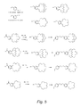
- FIG. 5 provides components and reactions used in the preparation of cyclic polyethers (including isomers, such as meta- and para-);
- FIG. 6 provides components and reactions used in the preparation of cyclic polyethers (including isomers, such as meta- and para-);
- FIG. 7 provides a synthetic pathway for cyclic polyether compounds with the following: (i) B r2 /Fe/C H2 C 12 ; (ii) n-butyllithium/THF, ⁇ 3 0 ° C.; (iii) bipyridine; (iv) dimethoxymethane, acetyl chloride, methanol, and SnC 14 in C H2 C 12 ; (v) ortho-phenanthroline-4-amine; (vi) 1-aza-15-crown-5 in THF; (vii) 2-hydroxymethyl-15-crown-5 in THF with NaH; (viii) 2-hydroxymethyl[2.2.1]cryptand in THF with NaH; (ix) 1-aza-18-crown-6 in THF; (x) 2-hydroxymethyl-18-crown-6 in THF with NaH; (xi) 2-hydroxymethyl[2.2.2]cryptand in THF with NaH;
- FIG. 8 provides a synthetic pathway for cyclic polyether compounds with the following: (i) TiCl 3 .AA/diethylaluminum chloride in toluene; (ii) 2-hydroxymethyl-18-crown-6 in THF with NaH; (iii) 2-hydroxymethyl[2.2.2]cyptand in THF with NaH; [Note: the other hydroxy-substituted ionophores (like those listed on the top in FIG. 4 ) are also possible; these might include (ii) 2-hydroxy-15-crown-5 in THF with NaH; same with (iii) 2-hydroxymethyl[2.2.1]cyptand in THF with NaH.
- FIG. 9 provides a plot of the proton conductivity versus relative humidity for a perfluorocyclobutane block copolymer ionomer with perfluorosulfonic acid side groups (PFCB-PFSA, see structure below) membrane having polymeric crown ether nanoparticles.
- PFCB-PFSA perfluorocyclobutane block copolymer ionomer with perfluorosulfonic acid side groups
- FIG. 10 provides a plot of the fuel cell performance for a 50 cm 2 -active area of cell voltage and high frequency resistance (HFR) at 1.5 A/cm 2 versus % R.H. at the cathode for a PFCB-PFSA membrane with 5 wt. % nano-particulate poly(vinylbenzo18-crown-6) added (higher-performing gray curve) and one without the polymeric crown ether additive (black curve) at 150 kPa;
- HFR high frequency resistance
- FIG. 11 provides a plot of the fuel cell performance versus fuel cell temperature for a 50 cm 2 -active area of cell voltage and high frequency resistance at 0.4 and 1.2 A/cm 2 for a PFCB-PFSA membrane with 5 wt. % nano-particulate poly(vinylbenzo18-crown-6) added;
- FIG. 12 provides a comparison of plots of the cell voltage and high frequency resistance versus current density at 55% relative humidity (R.H.) for PFCB-PFSA membranes prepared with and without 5 wt. % polymeric cyclic polyethers;
- FIG. 13 provides a comparison of plots of the cell voltage and high frequency resistance versus current density at 85% R.H. for PFCB-PFSA membranes made with and without 5 wt. % cyclic polyethers;
- FIG. 14 provides plots of the cell voltage and high frequency resistance versus current density at 150% R.H. for PFCB-PFSA membranes made with and without 5 wt. % cyclic polyethers.
- percent, “parts of,” and ratio values are by weight;
- the term “polymer” includes “oligomer,” “copolymer,” “terpolymer,” and the like; the description of a group or class of materials as suitable or preferred for a given purpose in connection with the invention implies that mixtures of any two or more of the members of the group or class are equally suitable or preferred; molecular weights provided for any polymers refers to number average molecular weight; description of constituents in chemical terms refers to the constituents at the time of addition to any combination specified in the description, and does not necessarily preclude chemical interactions among the constituents of a mixture once mixed; the first definition of an acronym or other abbreviation applies to all subsequent uses herein of the same abbreviation and applies mutatis mutandis to normal grammatical variations of the initially defined abbreviation; and, unless expressly stated to the contrary, measurement of a property is determined by the same technique as previously or later referenced for the same property.
- Fuel cell 10 includes the membrane electrode assembly 12 which includes anode catalyst layer 14 , cathode catalyst layer 16 , and ion conducting membrane (i.e., proton exchange membrane) 20 .
- Proton (i.e., ion) conducting membrane 20 is interposed between anode catalyst layer 14 and cathode catalyst layer 16 with anode catalyst layer 14 disposed over the first side of proton conducting membrane 20 and cathode catalyst layer 16 disposed over the first side of proton conducting membrane 20 .
- proton conducting membrane 20 includes an ion conducting polymer (i.e., an ionomer) having sulfonic acid groups and a compound having cyclic polyether groups.
- fuel cell 10 also includes porous gas diffusion layers 22 and 24 . Gas diffusion layer 22 is disposed over anode catalyst layer 14 while gas diffusion layer 24 is disposed over cathode catalyst layer 16 .
- fuel cell 10 includes anode flow field plate 26 disposed over gas diffusion layer 22 and cathode flow field plate 28 disposed over gas diffusion layer 24 .
- the membrane electrode assembly includes a proton conducting membrane having a first side and a second side.
- the proton exchange layer includes a second polymer having sulfonic acid groups and a plurality of nanoparticles comprising a first polymer having cyclic polyether groups.
- the nanoparticles are polymeric beads with cyclic polyether-containing groups appended thereto.
- Polymeric beads functionalized with cyclic polyether groups are made by the emulsion polymerization of styrene with 3 to 40 wt. % divinylbenzene as a crosslinking agent.
- Emulsion polymerized beads of vinyl monomers with ionophores are made typically with 10 wt % divinylbenzene as a crosslinking agent.
- cross-linked polystyrene beads with polymer anchored bipyridyl groups available from Sigma-Aldrich
- a poly(vinylbenzo-18-crown-6) in the form of 120 nm beads that are crosslinked with divinylbenzene are also useful in sequestering metal ions.
- the present embodiment includes a first polymer having cyclic polyether groups.
- the first polymer having cyclic polyether groups is a polymer.
- the first polymer having cyclic polyether groups is part of a polymeric bead.
- the cyclic polyether groups are monocyclic or polycyclic (e.g, 2 rings) having 12 to 45 member rings.
- the cyclic polyether groups are monocyclic or polycyclic (e.g, 2 rings) having 12 to 42 member rings.
- the cyclic polyether groups are monocyclic or polycyclic (e.g, 2 rings) having 12 to 39 member rings.
- the cyclic polyether groups are monocyclic or polycyclic (e.g, 2 rings) having 12 to 36 member rings.
- the size of each ring in the cyclic polyether groups is a multiple of three.
- suitable polymers having cyclic polyether groups include polymers or polymeric beads including crown ether or cryptand groups.
- one or more atoms in the polyether ring may be substituted by nitrogen atoms (azacrowns) or sulfur atoms (thiacrowns).
- the crown ether may also be substituted at any location along its polyether ring by any of a variety of groups known to those skilled in the art.
- the polymers having cyclic polyether groups are ionophores.
- Such ionophores work advantageously in three different ways.
- ionophores when added to ionomer solutions sequester metals ions which are initially present as impurities in the ionomers and the solvents.
- Some of the sequestered metal ions include the Fenton's active catalysts that form hydroxyl radical with hydrogen peroxide such as iron(II), nickel(II), cobalt(II) and copper ions.
- Other cations, such as aluminum(III), sodium, potassium, and the like, are also sequestered.
- these ions do not as readily form hydroxyl radicals by reaction with hydrogen peroxide in the membranes like the free ions such as Fe 2+ .
- Hydrogen peroxide is generated as a side reaction by the electrode catalyst during fuel cell operation, and hydroxyl radicals are known to cause chemical degradation failures in fuel cell membranes.
- the ionophores act as a chemical mitigant to prevent membrane degradation.
- these ionophores act to sequester metal ions that are introduced into the membranes as contaminants during fuel cell operation, and in particular, Fe 2+ generated from the reaction of acidic fuel cell by-products (such as HF) with stainless steel plates.
- the metal ionophore complexes prevent a parasitic, autocatalytic degradation due to Fe 2+ introduced during fuel cell operation.
- the ionophores with sequestered metal ions can be removed entirely from the ionomer coating solutions by centrifugation before the membrane is coated.
- the metal ions bind to the ionophores forming a complex which are removed by centrifugation.
- treatment of ionomer solutions can be used to purify ionomer solutions before membrane coating takes place.
- This separation process is especially advantageous when the ionophore-metal complexes are in the form of insoluble beads, fibers, particles precipitates, or sediments. All three mechanisms involving polymeric metal ionophore complexes are beneficial in improving the chemical stability of fuel cell membranes.
- cyclic polyether groups include, but are not limited to, the following structures:
- the line crossed by a wiggly line in chemical formulae represents the point of attachment of a chemical group to a polymer or other chemical group or structure.
- the first polymer having cyclic polyether groups is a polymer.
- the term polymer includes oligomers.
- such a polymer is a linear polymer.
- Such a linear polymer may be represented by the following formulae:
- R 1 is absent or a hydrocarbon group and CPG is a cyclic polyether group.
- CPG is a cyclic polyether group.
- the CPG are selected from the groups of formulae I through 23.
- hydrocarbon groups for R 1 include but are not limited to, C 1-20 alkyl groups, C 1-18 polyether groups, C 6-20 alkylaryl groups, C 6-20 aryl groups (e.g., phenyl, napthlyl, etc.), C 1-10 alkyl groups, or C 1-5 alkyl groups.
- alkylaryl groups are groups in which an alkyl group is attached to an aromatic group (e.g., phenyl).
- the alkyl group is bonded to the polymeric backbone and the aromatic group to the cyclic polyether group or the aromatic group is bonded to the polymeric backbone and the alkyl group is bonded to the cyclic polyether group.
- substituted groups include substituted or unsubstituted alkyl groups as well as branched or unbranched groups. Examples of substituted groups have one or more hydrogen atoms replaced by Cl, F, Br, OH, NO 2 , —CN, and the like.
- the polymers having formulae (24) and (25) are formed by polymerization of compounds having formula (26) and (27) respectively:
- the first polymer having cyclic polyether groups is present in an amount from about 1 to 15 weight percent of the total weight of the proton conducting membrane. In another refinement, the first polymer having cyclic polyether groups is present in an amount from about 2 to 10 weight percent of the total weight of the proton conducting membrane. In another refinement, the first polymer having cyclic polyether groups is present in an amount from about 3 to 7 weight percent of the total weight of the proton conducting membrane.
- the polycrown ethers, polymeric cryptands, and the like are added at about 1 to 15 wt. % of the ionomer, the cyclic polycrown additive can have from 1 to 100% of the monomers having cyclic polyether groups.
- the first polymer including cyclic polyether groups is a cyclic oligomer.
- cyclic oligomers may be formed from polymerization (e.g., emulsion polymerization) of compounds having formula 26 or 27 and a divinyl compound such as a compound described by formula 28:
- R 2 is a hydrocarbon group.
- suitable hydrocarbon groups for R 2 include, but are not limited to, C 1-20 alkyl groups, C 6-20 dialkylaryl groups, C 6-20 aryl groups (e.g., phenyl, napthlyl, etc), C 1-10 alkyl groups, or C 1-5 alkyl groups.
- a dialkylaryl group includes an aromatic ring with two alkyl groups bonded thereto.
- An example of such a cyclic oligomer has the following formula:
- the cyclic oligomer is formed by polymerization (e.g., emulsion polymerization) of a compound having formula 30:
- n and m are each independently an integer from 1 to 8.
- n and m are each independently an integer from 1 to 4.
- n and m are equal.
- Such polymerization may or may not be in the presence of a compound having formula 28.
- membrane electrode assembly 12 includes a second polymer having sulfonic acid groups.
- ion conducting polymers include, but are not limited to, perfluorosulfonic acid (PFSA) polymers, polymers having perfluorocyclobutyl moieties, and combinations thereof.
- Examples of useful PFSA polymers include a copolymer containing a polymerization unit based on a perfluorovinyl compound represented by: CF 2 ⁇ CF—(OCF 2 CFX 1 ) m —O r —(CF 2 ) q —SO 3 H where m represents an integer of from 0 to 3, q represents an integer of from 1 to 12, r represents 0 or 1, and X 1 represents a fluorine atom or a trifluoromethyl group and a polymerization unit based on tetrafluoroethylene.
- Suitable polymers including perfluorocyclobutyl moieties are disclosed in U.S. Pat. Pub. No. 2007/0099054, U.S. Pat. No.
- membrane electrode assembly 12 includes an anode catalyst layer 14 and cathode catalyst layer 16 .
- these catalyst layers are formed of porous conductive materials, such as woven graphite, graphitized sheets, or carbon paper to enable the fuel and oxidant to disperse over the surface of the membrane facing the fuel- and oxidant-supply electrodes, respectively.
- Each catalyst layer has finely divided catalyst particles (for example, platinum particles) supported on carbon particles to promote oxidation of hydrogen at the anode and reduction of oxygen at the cathode.
- the catalyst layers are formed by depositing a catalyst ink on ion conducting membrane 20 by direct spraying or coating in a shim frame.
- the catalyst layers are formed on a decal and transferred to ion conducting membrane 20 .
- a catalyst/ionomer ink can be coated on a gas diffusion medium substrate, which is known as a catalyst coated diffusion media (CCDM).
- the catalyst inks are typically prepared as a solution of a proton conducting polymer or ionomer (e.g. NAFIONTM), with particles of electrically conductive material, typically carbon, and particles of catalyst.
- the electrically conductive material, e.g., carbon is typically the catalyst support of the ink and the catalyst is typically a metal.
- the catalyst layer dispersion consists of a mixture of the precious metal catalyst supported on high surface carbon (e.g., Vulcan XC-72) and an ionomer solution such as NAFIONTM (DuPont Fluoroproducts, NC) in a solvent.
- useful catalysts include, but are not limited to, metals such as platinum, palladium; and mixtures of metals platinum and molybdenum, platinum and cobalt, platinum and ruthenium, platinum and nickel, and platinum and tin.
- the ionomer is typically purchased in a solvent and at the desired initial concentration. Additional solvent is optionally added to adjust the ionomer concentration to a desired concentration.
- the catalyst inks optionally contain polytetrafluoroethylene.
- the catalyst and catalyst support are dispersed in the ink by techniques such as ultrasonication or ball-milling.
- the average agglomerate size is in the range from 50 to 500 nm.
- the ink includes, for a 100 gram sample, an amount on the order of 0.5 to 5 grams of 5 to 80 wt. % catalytically active material on carbon (e.g., platinum on carbon), and on the order of 5 to 20 grams of 1 to 30 wt. % ionomer solution with a solvent.
- the weight ratio of ionomer to carbon is in the range of 0.20:1 to 2.0:1.
- the weight ratio of ionomer to carbon is in the range of 0.25:1 to 1:1.
- the ratio of solids to liquids in the ink is in the range of 0.15:1 to 0.35:1 (i.e., 13% to 27% by weight solids).
- a more preferred range is 0.2:1 to 0.3:1 or 16% to 23% by weight of solids in the slurry.
- the solvent makes up about 80% of the ink weight, and catalyst, ionomer, and carbon makes up the remaining 20%.
- Useful solvents include, but are not limited to, alcohols (e.g., propanol, ethanol, methanol), water, or a mixture of water and alcohols. Characteristically, the solvents evaporate at room temperature.
- alcohols e.g., propanol, ethanol, methanol
- a polyelectrolyte membrane is made by dispersing a polymer or ionophore having cyclic polyether groups (e.g., polycyclic crown ether or cryptand) with an ionomer in a liquid (as a solution, dispersion or suspension), followed by centrifugation and solution casting of the supernatant and then drying.
- a polymer or ionophore having cyclic polyether groups e.g., polycyclic crown ether or cryptand
- an ionomer in a liquid (as a solution, dispersion or suspension), followed by centrifugation and solution casting of the supernatant and then drying.
- ionophoric particles second polymer having cyclic polyether groups
- sequester cations such as Fe 2+
- ionophore polymer are added to a solution of the ionomer before solution casting of the membrane with added acid.
- the metal-cation ionophore polymer complex is then removed by filtration, centrifugation, and the like.
- the catalyst inks are homogenized by ball-milling for about three days before coating on the PEM, decal substrate, or gas diffusion medium.
- the catalyst loading can be controlled by the thickness of the shim; for the Mayer wire-wound rod coating, the catalyst loading can be controlled by the wire number. Multiple coatings can be applied for higher catalyst loading, as needed.
- the solvents are dried in an oven to drive off the solvent and form the electrode.
- the catalyst/ionomer coated decal dries, the catalyst/ionomer is then transferred onto a PEM by hot press to form an MEA. The anode and cathode can be hot-pressed onto a PEM simultaneously.
- Alcohols are easily converted to compounds with vinyl groups, for example by reaction with 1-(chloromethyl)-3-vinylbenzene or 1-(chloromethyl)-4-vinylbenzene.
- An alternative synthesis routes to 2-hydroxymethyl-18-crown-6,2-hydroxymethyl-15-crown-5, and 2-hydroxymethyl-[2.2.2]cryptand are reported in a Ph. D. thesis by David Alan Babb, “Synthesis and Metal Ion Complexation of Synthetic Ionophores,” A Ph.D. Dissertation in Chemistry, Texas Tech University, December, 1985; the entire disclosure of which is hereby incorporated by reference.
- a bisvinylbenzo-macrocyle is also made in one step by the reaction of compound 36 with methyltriphenylphosphonium bromide and n-butyllithium in diethyl ether or thetrahydrofuran (the Wittig reaction).
- Vinyl benzo[2.2.2]cryptand and vinyl[2.2.1]cryptand were prepared as shown in FIGS. 2 and 3 .
- the new vinylbenzo[2.2.2]cryptand (compound 36) and vinylbenzo[2.2.1]cryptand (compound 37) polymerize by radicals in emulsions.
- any known vinyl polymerization method is also possible including anionic, free radical and controlled free radical polymerization methods such as RAFT, nitroxyl mediated free radical, ATRP, and the like.
- Each of the vinylbenzl compounds such as compounds 34, 35, 36, and 37 are polymerized in emulsion with crosslinking dimers such as divinylbenzene or compound to form nanoparticulate beads which are further purified by dialysis. These polymers are then added to ionomers to scavenge metal ions before the coating of polyelectrolyte membranes.
- Polystyrene crosslinked with divinylbenzene in the form of beads, fibers, particulates and nanoparticles are functionalized with metal ionophores as shown in FIG. 7 . These materials are used as additives in polyelectrolyte membranes.
- Polyolefins are prepared by the Ziegler-Natta polymerization of 1-olefins and the polymerization proceeds with a variety of functional groups in FIG. 8 .
- undecylenyl iodide is polymerized and then the iodo group is replaced with ionophoric groups. These materials are added to ionomer coating solutions to form fuel cell membranes.
- Compound 41 Compound 1 (10 g) is dissolved in 400 mL of a 1:1 volume mixture of benzene and methanol, and then p-toluenesulfonic acid (2 g) is added. The mixture is heated to reflux for 16 h with continuous circulation of condensed vapors through anhydrous Na 2 SO 4 in a thimble of a Soxhlet extractor. The solvent is removed and an ether solution of the residue is washed with 5% aqueous NaHCO 3 . The ether layer is dried over Na 2 SO 4 and then removed to yield compound 41 (10 g).
- a small amount of pyridine (3 drops) is added as a catalyst which causes an immediate reaction.
- the flask is fitted with a drying tube and stirred for 48 h at 23° C.
- the mixture is then quickly filtered under nitrogen through a dry sintered glass Schlenk funnel, the solvent is evaporated in vacuo, and then co-evaporated once with dry benzene.
- the residue compound 43 is stirred under vacuum for 30 minutes and then used immediately after it is produced.
- the solution is cooled to 23° C., then cooled in an ice bath, and water (5 mL) is added slowly to destroy the excess BH 3 .
- the solution is evaporated in vacuo and the remaining solid is refluxed in a mixture of water (10 mL) and 6 N HCl (15 min) for 12 h.
- 50 wt. % NaOH is added slowly with stirring to adjust the pH to 10 and the solution is evaporated in vacuo.
- the resulting precipitate is washed with 2 ⁇ 30 mL of MeOH.
- the washings are combined after filtration and Et 2 O is added to precipitate the inorganic salts by adding a small amount of Et 2 O, filtering the solution, collecting the filtrate and then adding more Et 2 O. This is done repeatedly, evaporating some solution to reduce the volume needed, until no more solid precipitated from solution.
- the filtrate is evaporated in vacuo and the residue is purified by chromatography on alumina using CHCl 3 /MeOH (25:1) as eluent to give 4′-formylbenzo-[2.2.2]cryptand.
- the cyclic diamide in THF (20 mL) is added at 23° C. to a stirred suspension of LiAlH 4 in THF (20 mL).
- the mixture is cooled, and the solvent is removed using a rotary evaporator.
- the residue is washed with hexanes to remove residual unreacted ether and then is washed diethyl ether.
- Aqueous 10 wt. % hydrochloric acid (100 mL) is added and the mixture is extracted multiple times with CH 2 Cl 2 .
- the combined organic layers are separated with the aid of a centrifuge and then dried over sodium sulfate, filtered and then the solvent is evaporated.
- ratios used include: undecylenyl iodide (12 g), toluene (40 g), Et 2 AlCl (22 mL of a 1.8 M solution), TiCl 3 .AA (1 teaspoon), and then 16 h at 25° C.
- the mixture is centrifuged and the solids are washed with water and centrifuged. Increasing the reaction temperature turns the resultant polymer brown without further increasing the replacement of iodide by the 2-hydrorxymethyl-18-crown-6, as determined with infrared spectroscopy.
- the purged mixture is then heated at 70° C. for 2 h under argon with stirring.
- the reaction temperature is increased and is maintained at less than 80° C. for about 16 h.
- the mixture at 23° C. is transferred to a dialysis tube (Spectropore) and is dialyzed against 4 liters of water with two changes per day for 7 days.
- the milky dispersion is concentrated using a rotary evaporator and dry particles of polymer are obtained by freeze drying the dispersion.
- toluene (0.49 g), ether (0.19 g), and methylene chloride (0.213 g).
- the aqueous residue contains 0.014 g in emulsion.
- the polymer that forms during distillation at 80° C. contains 1.5 wt. % chlorine and consists of large (100 to 500 micrometer) flat flakes.
- This monomer is added to a mixture of potassium persulfate (0.01 g), sodium hydrogen phosphate (0.01 g) and sodium dodecylsulfate (0.1 g) in 20 mL of deionized water in a beverage bottle (6.5 fluid ounce volume) equipped with a rubber septum and a magnetic stir bar.
- the emulsion is sparged with argon for 30 minutes and is then heated at 70° C. for 24 hours. After cooling, the contents of the bottle are transferred to Spectropore dialysis tubing and dialyzed for 1 week against 4-liters of deionized water with water changes occurring at least twice per day.
- the residue is freeze dried to yield 1 gram of particles as shown in the following figure.
- the polymer is 63 wt. % (37.6 mol. %) crown ether, and the remainder is attributed to styrene moieties. After sieving of the powder, particles of less than 10 microns in dimension are obtained.
- Emulsion Polymerization of Styrene and Divinylbenzene with Persulfate In a soda pop bottle (6.5 fluid ounces) is placed 100 g water, 0.05 g potassium persulfate, 0.05 g sodium hydrogen phosphate, and 1 g sodium laurylsulfate. When this mixture dissolved, a mixture of styrene (25 g) and 3% divinylbenzene (DVB 0.77 g) is added. Nitrogen is bubbled through the mixture to replace the air and disperse the reactants. The nitrogen tube is removed and the bottle is capped and sealed, and the mixture is stirred at 70° C. for 2 h, then 95° C. for 2 h. The latex is transferred to a dialysis tube and dialyzed for 1 week with frequent water changes. After freeze-drying 24.2 g of product was obtained with an average particle size of 133 nanometers.
- Emulsion Polymerization of Styrene and 10 wt. % Divinylbenzene with Persulfate In a 3-necked, 500-mL, round-bottom flask equipped with a mechanical stirrer, condenser and argon inlet is placed 100 g water, 0.1 g potassium persulfate, 0.1 g sodium hydrogen phosphate, and 1 g sodium dodecylsulfate. When this mixture dissolved, a mixture of 25 g styrene and (2.78 g) of divinylbenzene (for 10 wt. % cross-linking) is added. After 30 minutes at 23° C., the mixture is stirred at 40° C.
- the latex is transferred to a dialysis tube and dialyzed for 1 week with frequent water changes.
- the average particle size is about 95.8 nm in diameter.
- the solvent is removed and the residue consists of an oil [hexanes soluble fraction consisting of 11.7% vinylbenzyl chloride and 88.3% 13-(4-vinylbenzyl)-1,4,7,10-tetraoxa-13-azacyclopentadecane with 8.6% unreacted 1-aza-15-crown-5 of the total mixture] and white crystals (hexanes insoluble fraction consisting of 3% vinylbenzyl chloride and 95.1% 13-(4-vinylbenzyl)-1,4,7,10-tetraoxa-13-azacyclopentadecane.
- the liquid (emulsion) is dialyzed against 4 liters of water for 1 week with frequent water changes and then the light-yellow polymer emulsion is then freeze-dried to yield particles of poly[13-(4-vinylbenzyl)-1,4,7,10-tetraoxa-13-azacyclopentadecane] and its meta-isomer.
- Chloromethylation of Emulsion Polymerized Styrene-Divinylbenzene Particles A solution of chloromethyl ether in methyl acetate is made by adding acetyl chloride (31.1 mL) to a mixture of dimethoxymethane (44 mL) and methanol (10 mL) to a 500-mL, 3-neck flask situated in an oil bath and equipped with a condenser, mechanical stirrer, argon inlet and addition funnel. To this mixture is added dichloromethane (130 mL).
- the polymer is collected and washed with methanol (two ⁇ 250 mL) using the Waring blender, isolated by filtration and rinsed with more methanol. The particles are then suspended and stirred for 2 hours in a jar with 90 mL of water and 10 mL of concentrated hydrochloric acid. The particles are filtered, washed with water (3 liters) and then with methanol (two times 200 mL). After isolation by filtration and drying, white particles are obtained.
- the % Br ranges between 32 and 35 wt. %. At 1 Br per each styrene group the calculated % Br is 44 wt. % and for 1 Br per two styrene groups, the calculated wt. % Br is 27.8. The yield of product is 7.398 g.
- the reaction mixture is allowed to stir for 16 hours at 23° C., and then air is bubbled into the reaction mixture until a color change is observed within two hours.
- the gold particles have 2,2-bipyridyl groups attached, presumably through the 2-position ortho- to the pyridyl N.
- the emulsion particles are about 150-nm in diameter.
- the particles are added at between 5 and 15 wt. % loading based on ionomer solids to NAFIONTM DE2020 in aqueous 1-propanol at 20 wt. % solids or to sulfonated perfluorocyclobutane ionomer in 1-propanol at 11.11 wt. % solids using an IKA homogenizer (Turrax T25).
- the dispersions are coated onto windowpane glass using a 6-mil Bird applicator (Gardco) and an Erichsen coater.
- the membranes are then dried on the platen at 80° C. and then the coated membrane films are floated off the glass with water and air dried.
- Emulsion Polymerization of 60 wt. %-Styrene and 40 wt. %-Divinylbenzene with Persulfate 60 wt. %-Styrene and 40 wt. %-Divinylbenzene with Persulfate.
- a soda pop bottle (6.5 fluid ounces) with a magnetic stirrer is placed 100 g water, 0.1 g potassium persulfate, 0.1 g sodium hydrogen phosphate, and 1 g sodium dodecyl sulfate. After this mixture dissolved, a mixture of styrene (10.446 g) and divinylbenzene (6.964 g) is added and the bottle is sealed with a rubber septum. Argon is passed over the emulsion to replace the air and disperse the reactants.
- the argon is removed and the mixture in the sealed bottle is stirred at 60° C. for 18 h, then 95° C. for 2 h.
- the latex contains 3.34 g of coarse polymer solids which are filtered off (with an 100- ⁇ m polypropylene mesh, Sefar) and discarded.
- the remaining emulsion is transferred to a dialysis tube and dialyzed for 1 week with frequent water changes. After freeze-drying 13.9 g of product is obtained.
- Emulsion Polymerization of 4′-Vinyl benzo-18-crown-6 To a 50-mL, one-neck flask with a 14/20 joint is added a stir bar, water (10 g), potassium persulfate (0.005 g), sodium hydrogen phosphate (0.005 g), and sodium dodecyl sulfate (0.05 g). After this mixture dissolves, 4′-vinylbenzo-18-crown-6 (Sigma-Aldrich, 1 g) and freshly distilled divinylbenzene (1 drop, 0.05 g) is added.
- the flask is then equipped with a reflux condenser, a yellow Keck clamp, and a rubber suba seal septum for sparging the liquid with argon using a long needle for an argon gas inlet and another needle connected to a silicone oil bubbler for an exit.
- Argon is passed over the emulsion to replace the air and disperse the reactants for 30 minutes.
- the argon is removed and the mixture in the sealed flask is stirred in a 70° C. oil bath for 2 h, then at 95° C. (oil bath set temperature) for 16 h.
- the cooled emulsion is transferred to a dialysis tube (Spectropore) and dialyzed for 1 week with frequent water changes.
- poly(vinylbenzo-18-crown-6) After freeze-drying 0.9 g of poly(vinylbenzo-18-crown-6) is obtained in the form of 120 nm diameter white beads. These beads are added to ionomer solutions such as TCT891.
- ionomer solutions such as TCT891.
- One fuel cell test is performed with the beads remaining suspended in the ionomer solution before coating at 5 wt. % poly(vinylbenzo-18-crown-6) based on ionomer solids.
- Another fuel cell test is performed after centrifuging the ionomer mixture and decanting the ionomer solution from the sediment at the bottom of the centrifuge vessel. The liquid ionomer phase is then coated into a fuel cell membrane.
- the particle size of the poly(vinylbenzo-18-crown-6) is shown below.
- TCT891 is a perfluorocyclobutane (compound 56) multi-block co-polymer with perfluorosulfonic acid side groups available from Tetramer Technologies, LLC.
- the structure is shown below.
- the molar ratio of biphenyl to hexafluoroisopropylidene biphenyl moieties is 2 to 1, and the ion exchange capacity of the polymer is 1.55 meq H + /g ionomer.
- the overall number average molecular weight of the polymer by size exclusion chromatography is 60,000, while that of the biphenyl chains is about 8,000.
- the hexafluoroisopropylidene biphenyl groups are interspersed between the 8000 molecular weight biphenyl segments in a less defined way, because these are introduced individually during the polymerization instead of being added as an oligomer segment.
- the polydispersity of the polymer defined as weight average molecular weight divided by number average molecular weight, is 1.3.
- the polymer is soluble in alcohols (methanol, ethanol, 1-propanol and isopropanol) and in polar aprotic solvents such as N,N-dimethylacetamide, N,N-dimethylformamide, and N-methylpyrrolidone.
- FIG. 9 provides a plot of the proton conductive versus relative humidity for a PFCB-PFSA membrane having polymeric crown ethers (NAFIONTM DE2020 membrane is provided as a reference). Although the proton conductivity of the membrane containing the poly(vinylbenzo-18-crown-6) is lower than that without the additive, the fuel cell performance of the membrane with the additive after centrifugation is better than the membrane before treatment.
- FIG. 10 provides a plot of the fuel cell performance for a 50 cm 2 -active area of cell voltage and high frequency resistance at 1.5 A/cm 2 versus relative humidity showing the performance advantage for the centrifuged crown-treated ionomer membrane [with 5 wt. % poly(vinylbenzo-8-crown-6) nanoparticles] as compared with that of the membrane made with the as-received ionomer.
- FIG. 11 is a plot of fuel cell performance versus temperature at 0.4 and 1.2 A/cm 2 for a PFCB-PFSA membrane with 5 wt. % nano-particulate poly(benzo-18-crown-6).
- FIGS. 12, 13 and 14 illustrate the performance enhancements of the centrifuged crown-containing membrane in the polarization curves at 55%, 85%, and 150% cathode out relative humidity (RH).
- FIGS. 12, 13 and 14 provide plots of the cell voltage and high frequency resistance versus current for various membranes having polymer with cyclic polyethers [5 wt. % poly(vinylbenzo-18-crown-6)].
Landscapes
- Chemical & Material Sciences (AREA)
- Engineering & Computer Science (AREA)
- Manufacturing & Machinery (AREA)
- Chemical Kinetics & Catalysis (AREA)
- Life Sciences & Earth Sciences (AREA)
- Sustainable Development (AREA)
- Sustainable Energy (AREA)
- Electrochemistry (AREA)
- General Chemical & Material Sciences (AREA)
- Inorganic Chemistry (AREA)
- Composite Materials (AREA)
- Materials Engineering (AREA)
- Health & Medical Sciences (AREA)
- Medicinal Chemistry (AREA)
- Polymers & Plastics (AREA)
- Organic Chemistry (AREA)
- Crystallography & Structural Chemistry (AREA)
- Dispersion Chemistry (AREA)
- Fuel Cell (AREA)
- Inert Electrodes (AREA)
Abstract
Description


As used herein, the line crossed by a wiggly line in chemical formulae represents the point of attachment of a chemical group to a polymer or other chemical group or structure.

where R1 is absent or a hydrocarbon group and CPG is a cyclic polyether group. When R1 is absent the polymer with formula (24) reduces to:
In a refinement, the CPG are selected from the groups of formulae I through 23. Examples of hydrocarbon groups for R1 include but are not limited to, C1-20 alkyl groups, C1-18 polyether groups, C6-20 alkylaryl groups, C6-20 aryl groups (e.g., phenyl, napthlyl, etc.), C1-10 alkyl groups, or C1-5 alkyl groups. As used herein, alkylaryl groups are groups in which an alkyl group is attached to an aromatic group (e.g., phenyl). In such groups, the alkyl group is bonded to the polymeric backbone and the aromatic group to the cyclic polyether group or the aromatic group is bonded to the polymeric backbone and the alkyl group is bonded to the cyclic polyether group. It should be appreciated that these examples include substituted or unsubstituted alkyl groups as well as branched or unbranched groups. Examples of substituted groups have one or more hydrogen atoms replaced by Cl, F, Br, OH, NO2, —CN, and the like. In a refinement, the polymers having formulae (24) and (25) are formed by polymerization of compounds having formula (26) and (27) respectively:

where R2 is a hydrocarbon group. Examples of suitable hydrocarbon groups for R2 include, but are not limited to, C1-20 alkyl groups, C6-20 dialkylaryl groups, C6-20 aryl groups (e.g., phenyl, napthlyl, etc), C1-10 alkyl groups, or C1-5 alkyl groups. A dialkylaryl group includes an aromatic ring with two alkyl groups bonded thereto. An example of such a cyclic oligomer has the following formula:


Structures analogous to 29A and B but made with vinylbenzo-15-crown-5 instead of vinylbenzo-18-crown-6 are also useful additives to the ionomers.

where n and m are each independently an integer from 1 to 8. In a refinement, n and m are each independently an integer from 1 to 4. In a further refinement, n and m are equal. Such polymerization may or may not be in the presence of a
CF2═CF—(OCF2CFX1)m—Or—(CF2)q—SO3H
where m represents an integer of from 0 to 3, q represents an integer of from 1 to 12, r represents 0 or 1, and X1 represents a fluorine atom or a trifluoromethyl group and a polymerization unit based on tetrafluoroethylene. Suitable polymers including perfluorocyclobutyl moieties are disclosed in U.S. Pat. Pub. No. 2007/0099054, U.S. Pat. No. 7,897,691 issued Mar. 1, 2011; U.S. Pat. No. 7,897,692 issued Mar. 1, 2011; U.S. Pat. No. 7,888,433 issued Feb. 15, 2011, U.S. Pat. No. 7,897,693 issued Mar. 1, 2011; and U.S. Pat. No. 8,053,530 issued Nov. 8, 2011, the entire disclosures of which are hereby incorporated by reference. Examples of perfluorocyclobutyl moieties are:


which also contains some unreacted vinylbenzyl chloride. About 20 mL of water is added and the mixture is extracted with 100 mL of hexanes. The hexanes layer contained about 1.48 grams of oil and the compound shown below and unreacted vinylbenzyl chloride. Distillation of this mixture produces oil and vinylbenzyl chloride in the volatile portion. The residue polymerizes. The aqueous layer is extracted with 100 mL of the following solvents which on drying yields compound 53:

in the amounts specified in parentheses: toluene (0.49 g), ether (0.19 g), and methylene chloride (0.213 g). The aqueous residue contains 0.014 g in emulsion. The polymer that forms during distillation at 80° C. contains 1.5 wt. % chlorine and consists of large (100 to 500 micrometer) flat flakes.


Polymers with this structure are further described in U.S. Pat. Nos. 7,897,691; 7,960,046; and 8,053,530.
Claims (10)


CF2═CF—(OCF2CFX1)m—Or—(CF2)q-SO3H

Priority Applications (3)
| Application Number | Priority Date | Filing Date | Title |
|---|---|---|---|
| US13/611,694 US9786941B2 (en) | 2012-09-12 | 2012-09-12 | Metal ionophores in PEM membranes |
| DE102013217839.5A DE102013217839B4 (en) | 2012-09-12 | 2013-09-06 | Membrane electrode assembly for a fuel cell |
| CN201310414224.2A CN103682392B (en) | 2012-09-12 | 2013-09-12 | Carriers of metal ions in PEM film |
Applications Claiming Priority (1)
| Application Number | Priority Date | Filing Date | Title |
|---|---|---|---|
| US13/611,694 US9786941B2 (en) | 2012-09-12 | 2012-09-12 | Metal ionophores in PEM membranes |
Publications (2)
| Publication Number | Publication Date |
|---|---|
| US20140072900A1 US20140072900A1 (en) | 2014-03-13 |
| US9786941B2 true US9786941B2 (en) | 2017-10-10 |
Family
ID=50153552
Family Applications (1)
| Application Number | Title | Priority Date | Filing Date |
|---|---|---|---|
| US13/611,694 Active 2035-05-19 US9786941B2 (en) | 2012-09-12 | 2012-09-12 | Metal ionophores in PEM membranes |
Country Status (3)
| Country | Link |
|---|---|
| US (1) | US9786941B2 (en) |
| CN (1) | CN103682392B (en) |
| DE (1) | DE102013217839B4 (en) |
Cited By (3)
| Publication number | Priority date | Publication date | Assignee | Title |
|---|---|---|---|---|
| US11020713B2 (en) * | 2018-06-29 | 2021-06-01 | Magna Imperio Systems Corp. | Ion selective membrane with ionophores |
| US11787777B1 (en) | 2022-11-04 | 2023-10-17 | Pall Corporation | Crown ether amines and methods of use |
| US11905269B1 (en) | 2022-11-04 | 2024-02-20 | Pall Corporation | Crown ether carbenes and methods of use |
Families Citing this family (4)
| Publication number | Priority date | Publication date | Assignee | Title |
|---|---|---|---|---|
| US10243241B2 (en) | 2015-12-01 | 2019-03-26 | GM Global Technology Operations LLC | Lithium ion battery with transition metal ion traps |
| CN106229555A (en) * | 2016-08-31 | 2016-12-14 | 井冈山大学 | The method that polymerization Azacrown ether containing coated separator improves manganese systems lithium ion battery service life |
| CN112436167B (en) * | 2020-11-17 | 2021-10-12 | 中国科学院兰州化学物理研究所 | A direct polyether compound fuel cell and system |
| CN119549146A (en) * | 2024-12-09 | 2025-03-04 | 嘉庚创新实验室 | A dual-site supported noble metal catalyst and its preparation method and application |
Citations (9)
| Publication number | Priority date | Publication date | Assignee | Title |
|---|---|---|---|---|
| US5312537A (en) * | 1989-07-20 | 1994-05-17 | Public Health Laboratory Service Board | Electrochemical cell, reference electrode and electrochemical method |
| KR20050119366A (en) * | 2004-06-16 | 2005-12-21 | 삼성에스디아이 주식회사 | A membrane for fuel cell and a fuel cell comprising the same |
| US20070099054A1 (en) | 2005-11-01 | 2007-05-03 | Fuller Timothy J | Sulfonated-perfluorocyclobutane polyelectrolyte membranes for fuel cells |
| US20100330451A1 (en) * | 2007-06-28 | 2010-12-30 | Kazuma Shinozaki | Electrode catalyst substrate and method for producing the same, and polymer electrolyte fuel cell |
| US7888433B2 (en) | 2008-05-09 | 2011-02-15 | Gm Global Technology Operations, Inc. | Sulfonated-polyperfluoro-cyclobutane-polyphenylene polymers for PEM fuel cell applications |
| US7897693B2 (en) | 2008-05-09 | 2011-03-01 | Gm Global Technology Operations, Inc. | Proton conductive polymer electrolytes and fuel cells |
| US7897692B2 (en) | 2008-05-09 | 2011-03-01 | Gm Global Technology Operations, Inc. | Sulfonated perfluorocyclobutane block copolymers and proton conductive polymer membranes |
| US7897691B2 (en) | 2008-05-09 | 2011-03-01 | Gm Global Technology Operations, Inc. | Proton exchange membranes for fuel cell applications |
| US8053530B2 (en) | 2009-08-26 | 2011-11-08 | GM Global Technology Operations LLC | Polyelectrolyte membranes made of poly(perfluorocyclobutanes) with pendant perfluorosulfonic acid groups and blends with poly(vinylidene fluoride) |
Family Cites Families (4)
| Publication number | Priority date | Publication date | Assignee | Title |
|---|---|---|---|---|
| DE10007654A1 (en) * | 2000-02-19 | 2001-09-06 | Forschungszentrum Juelich Gmbh | Membrane for fuel cells |
| US20060222920A1 (en) * | 2005-04-01 | 2006-10-05 | Belabbes Merzougui | Metal cations chelators for fuel cells |
| TWM292790U (en) | 2005-10-28 | 2006-06-21 | Antig Tech Co Ltd | Fuel cell device having operation parameter adjusting capability |
| JP4765908B2 (en) * | 2006-11-22 | 2011-09-07 | 旭硝子株式会社 | Solid polymer electrolyte membrane and membrane electrode assembly for solid polymer fuel cell |
-
2012
- 2012-09-12 US US13/611,694 patent/US9786941B2/en active Active
-
2013
- 2013-09-06 DE DE102013217839.5A patent/DE102013217839B4/en active Active
- 2013-09-12 CN CN201310414224.2A patent/CN103682392B/en active Active
Patent Citations (10)
| Publication number | Priority date | Publication date | Assignee | Title |
|---|---|---|---|---|
| US5312537A (en) * | 1989-07-20 | 1994-05-17 | Public Health Laboratory Service Board | Electrochemical cell, reference electrode and electrochemical method |
| KR20050119366A (en) * | 2004-06-16 | 2005-12-21 | 삼성에스디아이 주식회사 | A membrane for fuel cell and a fuel cell comprising the same |
| US20070099054A1 (en) | 2005-11-01 | 2007-05-03 | Fuller Timothy J | Sulfonated-perfluorocyclobutane polyelectrolyte membranes for fuel cells |
| US7960046B2 (en) | 2005-11-01 | 2011-06-14 | GM Global Technology Operations LLC | Sulfonated-perfluorocyclobutane polyelectrolyte membranes for fuel cells |
| US20100330451A1 (en) * | 2007-06-28 | 2010-12-30 | Kazuma Shinozaki | Electrode catalyst substrate and method for producing the same, and polymer electrolyte fuel cell |
| US7888433B2 (en) | 2008-05-09 | 2011-02-15 | Gm Global Technology Operations, Inc. | Sulfonated-polyperfluoro-cyclobutane-polyphenylene polymers for PEM fuel cell applications |
| US7897693B2 (en) | 2008-05-09 | 2011-03-01 | Gm Global Technology Operations, Inc. | Proton conductive polymer electrolytes and fuel cells |
| US7897692B2 (en) | 2008-05-09 | 2011-03-01 | Gm Global Technology Operations, Inc. | Sulfonated perfluorocyclobutane block copolymers and proton conductive polymer membranes |
| US7897691B2 (en) | 2008-05-09 | 2011-03-01 | Gm Global Technology Operations, Inc. | Proton exchange membranes for fuel cell applications |
| US8053530B2 (en) | 2009-08-26 | 2011-11-08 | GM Global Technology Operations LLC | Polyelectrolyte membranes made of poly(perfluorocyclobutanes) with pendant perfluorosulfonic acid groups and blends with poly(vinylidene fluoride) |
Non-Patent Citations (5)
| Title |
|---|
| Babb, D.A., "Synthesis and Metal Ion Complexation of Synthetic Ionophores," a Ph.D. Dissertation in Chemistry, Texas Tech University, Dec. 1985. |
| Jennifer A. Irvin, Polyimides for Battery and Fuel Cells Membranes, Fuel Chemistry Division Preprints, Mar. 27, 2003, 48(1), pp. 441-442. * |
| Kopolow, S. et al., "Poly(vinylmacrocyclic polyethers), Synthesis and Cation Binding Properties," Macromolecules, 1973, 6, 133. |
| Montanari, F. et al., "Hydroxymethyl Derivatives of 18-Crown-6 and [2.2.2]Cryptand: Versatile Intermediates for the Synthesis of Lipophilic and Polymer-Bonded Macrocyclic Ligands," J. Org. Chem., 1982, 47, 1298-1302. |
| Smid, J. et al., "Synthesis of 4′-vinylbenzocrown ethers," Organic Preparation and Procedures Int., 1976, 8(4), 193-196. |
Cited By (5)
| Publication number | Priority date | Publication date | Assignee | Title |
|---|---|---|---|---|
| US11020713B2 (en) * | 2018-06-29 | 2021-06-01 | Magna Imperio Systems Corp. | Ion selective membrane with ionophores |
| US11787777B1 (en) | 2022-11-04 | 2023-10-17 | Pall Corporation | Crown ether amines and methods of use |
| US11905269B1 (en) | 2022-11-04 | 2024-02-20 | Pall Corporation | Crown ether carbenes and methods of use |
| US12122758B2 (en) | 2022-11-04 | 2024-10-22 | Pall Corporation | Crown ether amines and methods of use |
| US12264144B2 (en) | 2022-11-04 | 2025-04-01 | Pall Corporation | Crown ether carbenes and methods of use |
Also Published As
| Publication number | Publication date |
|---|---|
| CN103682392B (en) | 2016-04-13 |
| DE102013217839B4 (en) | 2021-06-02 |
| US20140072900A1 (en) | 2014-03-13 |
| CN103682392A (en) | 2014-03-26 |
| DE102013217839A1 (en) | 2014-03-13 |
Similar Documents
| Publication | Publication Date | Title |
|---|---|---|
| US9786941B2 (en) | Metal ionophores in PEM membranes | |
| Mahmoud et al. | Highly conductive and alkaline stable partially fluorinated anion exchange membranes for alkaline fuel cells: Effect of ammonium head groups | |
| Zhang et al. | Anion exchange membranes based on tetra-quaternized poly (arylene ether ketone) | |
| US11394045B2 (en) | Electrolyte material, liquid composition comprising it and its use | |
| Li et al. | All‐carbon backbone aromatic polymers for proton exchange membranes | |
| CN114276505B (en) | Poly (arylene piperidine) copolymer containing polyethylene glycol flexible hydrophilic side chain, preparation method, anion exchange membrane and application | |
| US20210381119A1 (en) | Polymer electrolyte membrane, membrane electrode assembly and polymer electrolyte water electrolyzer | |
| WO2021250576A1 (en) | Process for recycling a solid article including a fluorinated polymer | |
| EP3476872B1 (en) | Electrolyte material, method for producing same, and use of same | |
| EP3239189B1 (en) | Electrolyte material, liquid composition and membrane/electrode assembly for polymer electrolyte fuel cell | |
| US20100047660A1 (en) | Development and characterization of novel proton conducting aromatic polyether type copolymers bearing main and side chain pyridine groups | |
| US20240213508A1 (en) | Fluorine-containing compound having sulfonic acid group and polymer electrolyte fuel cell | |
| Sato et al. | Synthesis of a cross-linked polymer electrolyte membrane with an ultra-high density of sulfonic acid groups | |
| US20160149250A1 (en) | Electrolyte membrane, membrane-electrode assembly, and solid polymer fuel cell | |
| Sharma et al. | Ion selective redox active anion exchange membrane: improved performance of vanadium redox flow battery | |
| US8795924B2 (en) | Crown ether containing PEM electrode | |
| Yoon et al. | Synthesis and properties of densely sulfonated polyketones (sPKs) with rigid backbone structure for PEM fuel cell application | |
| EP3892645A1 (en) | Perfluoropolymer, liquid composition, solid polymer electrolyte membrane, membrane electrode joint body, and solid polymer fuel cell | |
| Zhu et al. | Covalent organic frameworks with localized acid-base pairs confer enhanced proton conductivity | |
| Wang et al. | Self-organization behavior tuning nanophase separation morphology of sulfonated nonfluoroniated aromatic polymer membrane and its mechanism | |
| CN113307966B (en) | Copolymer containing tetramethylpiperidinium oxide quaternary ammonium salt and its preparation method and application | |
| US20070020500A1 (en) | Membrane-electrode structure for solid polymer fuel cell and solid polymer fuel cell | |
| JP5076310B2 (en) | Polymer electrolyte, polymer electrolyte membrane, membrane-electrode assembly, and solid polymer fuel cell | |
| Chang et al. | Sulfonated poly (fluorene-co-sulfone) ether membranes containing perfluorocyclobutane groups for fuel cell applications | |
| US9370750B2 (en) | Polyolefin-PFCB ionomer |
Legal Events
| Date | Code | Title | Description |
|---|---|---|---|
| AS | Assignment |
Owner name: GM GLOBAL TECHNOLOGY OPERATIONS LLC, MICHIGAN Free format text: ASSIGNMENT OF ASSIGNORS INTEREST;ASSIGNORS:FULLER, TIMOTHY J.;HALALAY, ION C.;ZOU, LIJUN;AND OTHERS;REEL/FRAME:028951/0246 Effective date: 20120806 |
|
| AS | Assignment |
Owner name: WILMINGTON TRUST COMPANY, DELAWARE Free format text: SECURITY AGREEMENT;ASSIGNOR:GM GLOBAL TECHNOLOGY OPERATIONS LLC;REEL/FRAME:030694/0500 Effective date: 20101027 |
|
| AS | Assignment |
Owner name: GM GLOBAL TECHNOLOGY OPERATIONS LLC, MICHIGAN Free format text: RELEASE BY SECURED PARTY;ASSIGNOR:WILMINGTON TRUST COMPANY;REEL/FRAME:034287/0415 Effective date: 20141017 |
|
| FEPP | Fee payment procedure |
Free format text: PAYOR NUMBER ASSIGNED (ORIGINAL EVENT CODE: ASPN) |
|
| STCF | Information on status: patent grant |
Free format text: PATENTED CASE |
|
| MAFP | Maintenance fee payment |
Free format text: PAYMENT OF MAINTENANCE FEE, 4TH YEAR, LARGE ENTITY (ORIGINAL EVENT CODE: M1551); ENTITY STATUS OF PATENT OWNER: LARGE ENTITY Year of fee payment: 4 |
|
| MAFP | Maintenance fee payment |
Free format text: PAYMENT OF MAINTENANCE FEE, 8TH YEAR, LARGE ENTITY (ORIGINAL EVENT CODE: M1552); ENTITY STATUS OF PATENT OWNER: LARGE ENTITY Year of fee payment: 8 |