US9784133B2 - Turbine frame and airfoil for turbine frame - Google Patents
Turbine frame and airfoil for turbine frame Download PDFInfo
- Publication number
- US9784133B2 US9784133B2 US14/676,385 US201514676385A US9784133B2 US 9784133 B2 US9784133 B2 US 9784133B2 US 201514676385 A US201514676385 A US 201514676385A US 9784133 B2 US9784133 B2 US 9784133B2
- Authority
- US
- United States
- Prior art keywords
- airfoil
- fairings
- turbine frame
- pressure surface
- join line
- Prior art date
- Legal status (The legal status is an assumption and is not a legal conclusion. Google has not performed a legal analysis and makes no representation as to the accuracy of the status listed.)
- Active, expires
Links
- 239000003351 stiffener Substances 0.000 claims description 23
- 239000007789 gas Substances 0.000 description 8
- 239000012080 ambient air Substances 0.000 description 4
- 239000000567 combustion gas Substances 0.000 description 4
- 230000003068 static effect Effects 0.000 description 4
- 238000002485 combustion reaction Methods 0.000 description 3
- 239000012530 fluid Substances 0.000 description 3
- 239000003570 air Substances 0.000 description 2
- 239000000284 extract Substances 0.000 description 2
- 238000009434 installation Methods 0.000 description 2
- 238000001816 cooling Methods 0.000 description 1
- 239000012809 cooling fluid Substances 0.000 description 1
- 238000010586 diagram Methods 0.000 description 1
- 239000000446 fuel Substances 0.000 description 1
- 238000012423 maintenance Methods 0.000 description 1
- 238000000034 method Methods 0.000 description 1
- 238000011144 upstream manufacturing Methods 0.000 description 1
Images


Classifications
-
- F—MECHANICAL ENGINEERING; LIGHTING; HEATING; WEAPONS; BLASTING
- F01—MACHINES OR ENGINES IN GENERAL; ENGINE PLANTS IN GENERAL; STEAM ENGINES
- F01D—NON-POSITIVE DISPLACEMENT MACHINES OR ENGINES, e.g. STEAM TURBINES
- F01D5/00—Blades; Blade-carrying members; Heating, heat-insulating, cooling or antivibration means on the blades or the members
- F01D5/12—Blades
- F01D5/14—Form or construction
- F01D5/141—Shape, i.e. outer, aerodynamic form
-
- F—MECHANICAL ENGINEERING; LIGHTING; HEATING; WEAPONS; BLASTING
- F01—MACHINES OR ENGINES IN GENERAL; ENGINE PLANTS IN GENERAL; STEAM ENGINES
- F01D—NON-POSITIVE DISPLACEMENT MACHINES OR ENGINES, e.g. STEAM TURBINES
- F01D25/00—Component parts, details, or accessories, not provided for in, or of interest apart from, other groups
- F01D25/24—Casings; Casing parts, e.g. diaphragms, casing fastenings
- F01D25/246—Fastening of diaphragms or stator-rings
-
- F—MECHANICAL ENGINEERING; LIGHTING; HEATING; WEAPONS; BLASTING
- F01—MACHINES OR ENGINES IN GENERAL; ENGINE PLANTS IN GENERAL; STEAM ENGINES
- F01D—NON-POSITIVE DISPLACEMENT MACHINES OR ENGINES, e.g. STEAM TURBINES
- F01D25/00—Component parts, details, or accessories, not provided for in, or of interest apart from, other groups
- F01D25/16—Arrangement of bearings; Supporting or mounting bearings in casings
- F01D25/162—Bearing supports
-
- F—MECHANICAL ENGINEERING; LIGHTING; HEATING; WEAPONS; BLASTING
- F01—MACHINES OR ENGINES IN GENERAL; ENGINE PLANTS IN GENERAL; STEAM ENGINES
- F01D—NON-POSITIVE DISPLACEMENT MACHINES OR ENGINES, e.g. STEAM TURBINES
- F01D9/00—Stators
- F01D9/02—Nozzles; Nozzle boxes; Stator blades; Guide conduits, e.g. individual nozzles
- F01D9/04—Nozzles; Nozzle boxes; Stator blades; Guide conduits, e.g. individual nozzles forming ring or sector
- F01D9/041—Nozzles; Nozzle boxes; Stator blades; Guide conduits, e.g. individual nozzles forming ring or sector using blades
-
- F—MECHANICAL ENGINEERING; LIGHTING; HEATING; WEAPONS; BLASTING
- F01—MACHINES OR ENGINES IN GENERAL; ENGINE PLANTS IN GENERAL; STEAM ENGINES
- F01D—NON-POSITIVE DISPLACEMENT MACHINES OR ENGINES, e.g. STEAM TURBINES
- F01D9/00—Stators
- F01D9/02—Nozzles; Nozzle boxes; Stator blades; Guide conduits, e.g. individual nozzles
- F01D9/04—Nozzles; Nozzle boxes; Stator blades; Guide conduits, e.g. individual nozzles forming ring or sector
- F01D9/042—Nozzles; Nozzle boxes; Stator blades; Guide conduits, e.g. individual nozzles forming ring or sector fixing blades to stators
-
- F—MECHANICAL ENGINEERING; LIGHTING; HEATING; WEAPONS; BLASTING
- F05—INDEXING SCHEMES RELATING TO ENGINES OR PUMPS IN VARIOUS SUBCLASSES OF CLASSES F01-F04
- F05D—INDEXING SCHEME FOR ASPECTS RELATING TO NON-POSITIVE-DISPLACEMENT MACHINES OR ENGINES, GAS-TURBINES OR JET-PROPULSION PLANTS
- F05D2220/00—Application
- F05D2220/30—Application in turbines
- F05D2220/32—Application in turbines in gas turbines
-
- F—MECHANICAL ENGINEERING; LIGHTING; HEATING; WEAPONS; BLASTING
- F05—INDEXING SCHEMES RELATING TO ENGINES OR PUMPS IN VARIOUS SUBCLASSES OF CLASSES F01-F04
- F05D—INDEXING SCHEME FOR ASPECTS RELATING TO NON-POSITIVE-DISPLACEMENT MACHINES OR ENGINES, GAS-TURBINES OR JET-PROPULSION PLANTS
- F05D2240/00—Components
- F05D2240/10—Stators
- F05D2240/12—Fluid guiding means, e.g. vanes
-
- F—MECHANICAL ENGINEERING; LIGHTING; HEATING; WEAPONS; BLASTING
- F05—INDEXING SCHEMES RELATING TO ENGINES OR PUMPS IN VARIOUS SUBCLASSES OF CLASSES F01-F04
- F05D—INDEXING SCHEME FOR ASPECTS RELATING TO NON-POSITIVE-DISPLACEMENT MACHINES OR ENGINES, GAS-TURBINES OR JET-PROPULSION PLANTS
- F05D2240/00—Components
- F05D2240/10—Stators
- F05D2240/14—Casings or housings protecting or supporting assemblies within
Definitions
- Turbine engines and particularly gas or combustion turbine engines, are rotary engines that extract energy from a flow of combusted gases passing through the engine onto a multitude of turbine blades.
- Gas turbine engines typically include a stationary turbine frame supporting a plurality of circumferentially spaced vanes having an airfoil shape, which are exposed to high temperatures in operation. It is desirable to increase operating temperatures within gas turbine engines as much as possible to increase both output and efficiency.
- a one-piece wraparound fairing can be used.
- This configuration requires the struts be separable from the frame assembly at the hub, outer ring or both to permit fairing installation over the struts. This makes installation and field maintenance difficult.
- a split fairing arrangement in which forward and aft sections are sandwiched around the struts can be used but relies on an interlocking feature to keep the fairing halves together after assembly to the frame. This interlocking feature consumes a significant amount of physical space and is therefore is less desirable for use with many frame configurations as it increases aerodynamic blockage.
- an embodiment of the invention relates to an airfoil for a turbine frame having inner and outer hubs connected by a plurality of struts with a maximum width portion relative to an axial center of the turbine frame, the airfoil comprising, at least first and second fairings connected together along first and second join lines to form the airfoil and define an interior sized to receive one of the struts when the first and second fairings are mounted to the turbine frame, wherein the first join lines are located such that the first join line is forward of the maximum width portion and the second join line is aft of the maximum width portion when the first and second fairings are mounted to the turbine frame and a strut is received within the interior.
- an embodiment of the invention relates to a turbine frame for a turbine engine having an axial centerline
- the turbine frame includes an inner hub, an outer hub encircling the inner hub, a plurality of struts extending between the inner and outer hubs and having a maximum width portion relative to the axial centerline, an airfoil comprising at least first and second fairings mounted to the inner and outer hubs and encircling one of the struts, and abutting along first and second join lines, with the first join line located axially forward of the second join line.
- FIG. 1 is a schematic cross-sectional diagram of a gas turbine engine for an aircraft.
- FIG. 2 is a perspective view of a turbine exhaust frame of the engine from FIG. 1 .
- FIG. 3 is an exploded view of the turbine exhaust frame of FIG. 2 .
- FIG. 4 is a cross section of a prior art single-piece airfoil for a turbine frame.
- FIG. 5 is a cross section of a prior art example of a multi-piece or split airfoil cross section for a turbine frame.
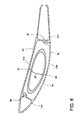
- FIG. 6 is a cross-sectional view of an airfoil vane taken along line VI-VI of FIG. 2 .
- FIG. 1 illustrates a gas turbine engine 10 for an aircraft.
- the engine 10 has a generally longitudinally extending axis or centerline 12 extending forward 14 to aft 16 .
- the engine 10 includes, in downstream serial flow relationship, a fan section 18 including a fan 20 , a compressor section 22 including a booster or low pressure (LP) compressor 24 and a high pressure (HP) compressor 26 , a combustion section 28 including a combustor 30 , a turbine section 32 including a HP turbine 34 , and a LP turbine 36 , and an exhaust section 38 .
- LP booster or low pressure
- HP high pressure
- the fan section 18 includes a fan casing 40 surrounding the fan 20 .
- the fan 20 includes a plurality of fan blades 42 disposed radially about the centerline 12 .
- the HP compressor 26 , the combustor 30 , and the HP turbine 34 form a core 44 of the engine 10 which generates combustion gases.
- the core 44 is surrounded by a core casing 46 which can be coupled with the fan casing 40 .
- a HP shaft or spool 48 disposed coaxially about the centerline 12 of the engine 10 drivingly connects the HP turbine 34 to the HP compressor 26 .
- a LP shaft or spool 50 which is disposed coaxially about the centerline 12 of the engine 10 within the larger diameter annular HP spool 48 , drivingly connects the LP turbine 36 to the LP compressor 24 and fan 20 .
- the LP compressor 24 and the HP compressor 26 respectively include a plurality of compressor stages 52 , 54 , in which a set of compressor blades 56 , 58 rotate relative to a corresponding set of static compressor vanes 60 , 62 (also called a nozzle) to compress or pressurize the stream of fluid passing through the stage.
- a set of compressor blades 56 , 58 rotate relative to a corresponding set of static compressor vanes 60 , 62 (also called a nozzle) to compress or pressurize the stream of fluid passing through the stage.
- multiple compressor blades 56 , 58 may be provided in a ring and may extend radially outwardly relative to the centerline 12 , from a blade platform to a blade tip, while the corresponding static compressor vanes 60 , 62 are positioned downstream of and adjacent to the rotating blades 56 , 58 .
- the HP turbine 34 and the LP turbine 36 respectively include a plurality of turbine stages 64 , 66 , in which a set of turbine blades 68 , 70 are rotated relative to a corresponding set of static turbine vanes 72 , 74 (also called a nozzle) to extract energy from the stream of fluid passing through the stage.
- a single turbine stage 64 , 66 multiple turbine blades 68 , 70 may be provided in a ring and may extend radially outwardly relative to the centerline 12 , from a blade platform to a blade tip, while the corresponding static turbine vanes 72 , 74 are positioned upstream of and adjacent to the rotating blades 68 , 70 .
- the rotating fan 20 supplies ambient air to the LP compressor 24 , which then supplies pressurized ambient air to the HP compressor 26 , which further pressurizes the ambient air.
- the pressurized air from the HP compressor 26 is mixed with fuel in combustor 30 and ignited, thereby generating combustion gases. Some work is extracted from these gases by the HP turbine 34 , which drives the HP compressor 26 .
- the combustion gases are discharged into the LP turbine 36 , which extracts additional work to drive the LP compressor 24 , and the exhaust gas is ultimately discharged from the engine 10 via the exhaust section 38 .
- the driving of the LP turbine 36 drives the LP spool 50 to rotate the fan 20 and the LP compressor 24 .
- Some of the ambient air supplied by the fan 20 may bypass the engine core 44 and be used for cooling of portions, especially hot portions, of the engine 10 , and/or used to cool or power other aspects of the aircraft.
- the hot portions of the engine are normally downstream of the combustor 30 , especially the turbine section 32 , with the HP turbine 34 being the hottest portion as it is directly downstream of the combustion section 28 .
- Other sources of cooling fluid may be, but is not limited to, fluid discharged from the LP compressor 24 or the HP compressor 26 .
- FIG. 2 illustrates the structural details of an exhaust frame 80 supporting the LP/HP turbine vanes 72 , 74 of FIG. 1 . So as not to limit what section of the turbine the exhaust frame 80 may be utilized in, the vanes in the remaining figures have been given alternative numerals. It will be understood however that if the exhaust frame was for the high pressure turbine, then it would correspond to turbine vanes 72 and if the exhaust frame was for the low pressure turbine, then the vanes of the exhaust frame would correspond to the low pressure vanes 74 .
- the exhaust frame 80 may provide a structural load path from bearings, which support the rotating shafts of the engine 10 to an outer casing of the engine 10 .
- the exhaust frame 80 crosses the combustion gas flow path of the turbine section 32 and is thus exposed to high temperatures in operation.
- An inner hub 82 , an outer hub 84 encircling the inner hub 82 , and a plurality of struts 86 (shown in phantom) extending between the inner hub 82 and the outer hub 84 may be included in the exhaust frame 80 .
- Conduits 83 may run through some of the struts 86 and additional structures such as hangers and retainers 87 may be included in the exhaust frame 80 .
- vanes 88 and 90 there may be any number of vanes 88 and 90 included in the exhaust frame 80 .
- the vanes 88 and 90 may have airfoil shapes and may create an airfoil cascade. During operation, the vanes 88 and 90 shape the air flow to improve the engine efficiency.
- the struts 86 which are not an airfoil shape, would negatively impact the airflow; therefore, the vanes 90 are included to form an airfoil around the struts 86 . It will be understood that in the illustrated example the vanes 90 surround structural elements, like the struts 86 while the vanes 88 surround nothing.
- FIG. 3 illustrates an exploded view of the exhaust frame 80 to illustrate this more clearly.
- FIGS. 4 and 5 illustrate two prior art aerodynamic vanes that have previously been used to cover struts in conventional engines.
- FIG. 4 illustrates a prior art turbine vane in the form of a single-piece vane 76 that has an airfoil shape. The single-piece vane 76 required the exhaust frame it is used with to be manufactured in at least two pieces to facilitate assembly.
- FIG. 5 illustrates an alternative prior art vane 78 that includes a split plane that includes the stacking axis 79 . Because the split plane is along the stacking axis 79 , the vane 78 requires a greater circumferential thickness, thereby increasing area blockage.
- embodiments of the invention include split fairings with the split lines being staggered relative to the frame struts, which enables a reduction in the cross-sectional width of the airfoil to reduce aerodynamic blockage.
- the airfoil or vane 90 ( FIG. 2 ), which may be included in the exhaust frame 80 may include a first fairing 92 and a second fairing 94 . Both the first fairing 92 and a second fairing 94 may be mounted to both the inner hub 82 and the outer hub 84 .
- the first and second fairings 92 and 94 may be mounted to the inner and outer hubs 82 and 84 in any suitable manner including that the first and second fairings 92 and 94 may be directly mounted to the inner and outer hubs 82 and 84 or they may have opposing end plates mounted to a corresponding one of the inner and outer hubs 82 and 84 .
- the vane 90 may encircle one of the struts 86 and the first fairing 92 and the second fairing 94 may abut along a first join line 96 and a second join line 98 .
- the first and second fairings 92 and 94 connect together along the first and second join lines 96 and 98 to define an interior 99 sized to receive one of the struts 86 .
- the strut 86 has a maximum width portion 89 and the first and second join lines 96 and 98 are located on axially opposite sides of the maximum width portion 89 .
- the first join line 96 may be located axially forward of the second join line 98 .
- the first join line 96 is located such that the first join line 96 is forward of the maximum width portion 89 of the strut 86 and the second join line 98 is aft of the maximum width portion 89 when the first and second fairings 92 and 94 are mounted to the exhaust frame 80 and the strut 86 is received within the interior 99 .
- the width of the vane 90 at either of the first and second join lines 96 and 98 may be less than the width of the maximum width portion 89 . This may include that the width of the vane 90 at both of the first and second join lines 96 and 98 is less than the width at the maximum width portion 89 .
- the vane 90 may have any suitable cross section including that the vane 90 may have an asymmetrical cross section as illustrated.
- a first stiffener 100 may extend between the first and second fairings 92 and 94 and the first join line 96 may be located at the first stiffener 100 .
- a second stiffener 102 may extend between the first and second fairings 92 and 94 and the second join line 98 may be located at the second stiffener 102 .
- the first and second stiffeners 100 and 102 may be axially spaced from each other and the interior 99 is located between the first and second stiffeners 100 and 102 .
- Both a high pressure surface 104 and a low pressure surface 106 may be formed by the vane 90 .
- each of the first and second fairings 92 and 94 form at least a portion of each of the high and low pressure surfaces 104 and 106 .
- the embodiments described above provide for a variety of benefits including that the split fairings act as covers of the struts of the structural exhaust frame and that a single piece exhaust frame may be utilized. Further, the airfoil includes split lines that are staggered about the struts to minimize the airfoil maximum circumferential thickness, thereby reducing aerodynamic blockage. Thus, the above described embodiments reduce pressure losses resulting in commercial advantages such as reduced frame aerodynamic losses and allowing for increased operating temperatures and increased efficiency.
Landscapes
- Engineering & Computer Science (AREA)
- Mechanical Engineering (AREA)
- General Engineering & Computer Science (AREA)
- Physics & Mathematics (AREA)
- Fluid Mechanics (AREA)
- Turbine Rotor Nozzle Sealing (AREA)
- Structures Of Non-Positive Displacement Pumps (AREA)
- Details Of Aerials (AREA)
Abstract
Description
Claims (20)
Priority Applications (6)
| Application Number | Priority Date | Filing Date | Title |
|---|---|---|---|
| US14/676,385 US9784133B2 (en) | 2015-04-01 | 2015-04-01 | Turbine frame and airfoil for turbine frame |
| JP2016062961A JP2016194297A (en) | 2015-04-01 | 2016-03-28 | Turbine frame and airfoil for turbine frame |
| CA2925537A CA2925537A1 (en) | 2015-04-01 | 2016-03-30 | Turbine frame and airfoil for turbine frame |
| EP16163348.2A EP3075968A1 (en) | 2015-04-01 | 2016-03-31 | Turbine frame and airfoil for a turbine frame |
| BR102016007109A BR102016007109A2 (en) | 2015-04-01 | 2016-03-31 | airfoil for a turbine frame |
| CN201610198591.7A CN106050314B (en) | 2015-04-01 | 2016-04-01 | Turbine frame and airfoil for turbine frame |
Applications Claiming Priority (1)
| Application Number | Priority Date | Filing Date | Title |
|---|---|---|---|
| US14/676,385 US9784133B2 (en) | 2015-04-01 | 2015-04-01 | Turbine frame and airfoil for turbine frame |
Publications (2)
| Publication Number | Publication Date |
|---|---|
| US20160290169A1 US20160290169A1 (en) | 2016-10-06 |
| US9784133B2 true US9784133B2 (en) | 2017-10-10 |
Family
ID=55646453
Family Applications (1)
| Application Number | Title | Priority Date | Filing Date |
|---|---|---|---|
| US14/676,385 Active 2035-12-04 US9784133B2 (en) | 2015-04-01 | 2015-04-01 | Turbine frame and airfoil for turbine frame |
Country Status (6)
| Country | Link |
|---|---|
| US (1) | US9784133B2 (en) |
| EP (1) | EP3075968A1 (en) |
| JP (1) | JP2016194297A (en) |
| CN (1) | CN106050314B (en) |
| BR (1) | BR102016007109A2 (en) |
| CA (1) | CA2925537A1 (en) |
Cited By (5)
| Publication number | Priority date | Publication date | Assignee | Title |
|---|---|---|---|---|
| US20190101026A1 (en) * | 2017-10-02 | 2019-04-04 | Safran Aircraft Engines | Arm for turbomachine casing comprising a body and a removable part |
| US20190242271A1 (en) * | 2018-02-02 | 2019-08-08 | Safran Aero Boosters Sa | Structural Casing for an Axial Turbine Engine |
| US11339665B2 (en) * | 2020-03-12 | 2022-05-24 | General Electric Company | Blade and airfoil damping configurations |
| US11454128B2 (en) * | 2018-08-06 | 2022-09-27 | General Electric Company | Fairing assembly |
| US11773735B2 (en) | 2021-12-22 | 2023-10-03 | Rolls-Royce Plc | Vane ring assembly with ceramic matrix composite airfoils |
Families Citing this family (7)
| Publication number | Priority date | Publication date | Assignee | Title |
|---|---|---|---|---|
| ES2774176T3 (en) * | 2015-10-20 | 2020-07-17 | MTU Aero Engines AG | Intermediate housing for a gas turbine |
| US10550726B2 (en) | 2017-01-30 | 2020-02-04 | General Electric Company | Turbine spider frame with additive core |
| US10781721B2 (en) * | 2018-02-09 | 2020-09-22 | General Electric Company | Integral turbine center frame |
| US10724390B2 (en) * | 2018-03-16 | 2020-07-28 | General Electric Company | Collar support assembly for airfoils |
| KR102441613B1 (en) * | 2020-03-05 | 2022-09-06 | 두산에너빌리티 주식회사 | Exhaust diffuser struts reduce flow separation |
| DE102020203547A1 (en) * | 2020-03-19 | 2021-09-23 | Siemens Aktiengesellschaft | Method of customizing a turbine assembly, fairing, multi-fairing kit, usage and diffuser |
| US11428160B2 (en) | 2020-12-31 | 2022-08-30 | General Electric Company | Gas turbine engine with interdigitated turbine and gear assembly |
Citations (28)
| Publication number | Priority date | Publication date | Assignee | Title |
|---|---|---|---|---|
| US94162A (en) * | 1869-08-24 | Improvement in water-wheels | ||
| US3237918A (en) * | 1963-08-30 | 1966-03-01 | Gen Electric | Variable stator vanes |
| US4793770A (en) | 1987-08-06 | 1988-12-27 | General Electric Company | Gas turbine engine frame assembly |
| US4897020A (en) * | 1988-05-17 | 1990-01-30 | Rolls-Royce Plc | Nozzle guide vane for a gas turbine engine |
| US4993918A (en) * | 1989-05-19 | 1991-02-19 | United Technologies Corporation | Replaceable fairing for a turbine exhaust case |
| US5020318A (en) * | 1987-11-05 | 1991-06-04 | General Electric Company | Aircraft engine frame construction |
| US5332357A (en) * | 1992-04-23 | 1994-07-26 | Industria De Turbo Propulsores S.A. | Stator vane assembly for controlling air flow in a gas turbine engien |
| US5357744A (en) | 1992-06-09 | 1994-10-25 | General Electric Company | Segmented turbine flowpath assembly |
| US5634767A (en) | 1996-03-29 | 1997-06-03 | General Electric Company | Turbine frame having spindle mounted liner |
| US5931636A (en) * | 1997-08-28 | 1999-08-03 | General Electric Company | Variable area turbine nozzle |
| US5941537A (en) * | 1997-09-05 | 1999-08-24 | General Eletric Company | Pressure actuated static seal |
| US6439841B1 (en) | 2000-04-29 | 2002-08-27 | General Electric Company | Turbine frame assembly |
| US20030161716A1 (en) | 2002-02-25 | 2003-08-28 | Honeywell International, Inc. | Method of forming a thermally isolated gas turbine engine housing |
| US6672833B2 (en) | 2001-12-18 | 2004-01-06 | General Electric Company | Gas turbine engine frame flowpath liner support |
| US20040088989A1 (en) * | 2002-11-07 | 2004-05-13 | Siemens Westinghouse Power Corporation | Variable exhaust struts shields |
| JP2005180418A (en) | 2003-12-22 | 2005-07-07 | General Electric Co <Ge> | Method and apparatus for assembling a gas turbine engine |
| CN101153546A (en) | 2006-09-28 | 2008-04-02 | 三菱重工业株式会社 | Doppelwellen-gasturbine |
| US20100104432A1 (en) | 2007-03-06 | 2010-04-29 | Magnus Hasselqvist | Arrangement for a gas turbine engine |
| US20100135777A1 (en) | 2008-11-29 | 2010-06-03 | John Alan Manteiga | Split fairing for a gas turbine engine |
| US20100132374A1 (en) * | 2008-11-29 | 2010-06-03 | John Alan Manteiga | Turbine frame assembly and method for a gas turbine engine |
| US20110302929A1 (en) * | 2010-06-10 | 2011-12-15 | Alstom Technology Ltd | Exhaust gas housing for a gas turbine and method for producing same |
| US20130167552A1 (en) | 2012-01-04 | 2013-07-04 | General Electric Company | Exhaust strut and turbomachine incorprating same |
| US20130336782A1 (en) | 2012-06-15 | 2013-12-19 | General Electric Company | Tripod buckle for split fairing of a gas turbine engine |
| WO2014022358A1 (en) | 2012-08-01 | 2014-02-06 | General Electric Company | Buckle joint for split fairing of a gas turbine engine |
| US20140178187A1 (en) | 2012-12-20 | 2014-06-26 | General Electric Company | Staggered double row, slotted airfoil design for gas turbine exhaust frame |
| US20140352313A1 (en) * | 2013-05-31 | 2014-12-04 | General Electric Company | Diffuser strut fairing |
| WO2014197037A2 (en) | 2013-03-11 | 2014-12-11 | United Technologies Corporation | Bench aft sub-assembly for turbine exhaust case fairing |
| US20160290168A1 (en) | 2015-04-01 | 2016-10-06 | General Electric Company | Turbine exhaust frame and method of vane assembly |
-
2015
- 2015-04-01 US US14/676,385 patent/US9784133B2/en active Active
-
2016
- 2016-03-28 JP JP2016062961A patent/JP2016194297A/en active Pending
- 2016-03-30 CA CA2925537A patent/CA2925537A1/en not_active Abandoned
- 2016-03-31 BR BR102016007109A patent/BR102016007109A2/en not_active IP Right Cessation
- 2016-03-31 EP EP16163348.2A patent/EP3075968A1/en not_active Withdrawn
- 2016-04-01 CN CN201610198591.7A patent/CN106050314B/en active Active
Patent Citations (33)
| Publication number | Priority date | Publication date | Assignee | Title |
|---|---|---|---|---|
| US94162A (en) * | 1869-08-24 | Improvement in water-wheels | ||
| US3237918A (en) * | 1963-08-30 | 1966-03-01 | Gen Electric | Variable stator vanes |
| US4793770A (en) | 1987-08-06 | 1988-12-27 | General Electric Company | Gas turbine engine frame assembly |
| US5020318A (en) * | 1987-11-05 | 1991-06-04 | General Electric Company | Aircraft engine frame construction |
| US4897020A (en) * | 1988-05-17 | 1990-01-30 | Rolls-Royce Plc | Nozzle guide vane for a gas turbine engine |
| US4993918A (en) * | 1989-05-19 | 1991-02-19 | United Technologies Corporation | Replaceable fairing for a turbine exhaust case |
| US5332357A (en) * | 1992-04-23 | 1994-07-26 | Industria De Turbo Propulsores S.A. | Stator vane assembly for controlling air flow in a gas turbine engien |
| US5357744A (en) | 1992-06-09 | 1994-10-25 | General Electric Company | Segmented turbine flowpath assembly |
| US5634767A (en) | 1996-03-29 | 1997-06-03 | General Electric Company | Turbine frame having spindle mounted liner |
| US5931636A (en) * | 1997-08-28 | 1999-08-03 | General Electric Company | Variable area turbine nozzle |
| US5941537A (en) * | 1997-09-05 | 1999-08-24 | General Eletric Company | Pressure actuated static seal |
| US6439841B1 (en) | 2000-04-29 | 2002-08-27 | General Electric Company | Turbine frame assembly |
| US6672833B2 (en) | 2001-12-18 | 2004-01-06 | General Electric Company | Gas turbine engine frame flowpath liner support |
| US20030161716A1 (en) | 2002-02-25 | 2003-08-28 | Honeywell International, Inc. | Method of forming a thermally isolated gas turbine engine housing |
| US20040088989A1 (en) * | 2002-11-07 | 2004-05-13 | Siemens Westinghouse Power Corporation | Variable exhaust struts shields |
| US6983608B2 (en) | 2003-12-22 | 2006-01-10 | General Electric Company | Methods and apparatus for assembling gas turbine engines |
| JP2005180418A (en) | 2003-12-22 | 2005-07-07 | General Electric Co <Ge> | Method and apparatus for assembling a gas turbine engine |
| CN101153546A (en) | 2006-09-28 | 2008-04-02 | 三菱重工业株式会社 | Doppelwellen-gasturbine |
| US20100303608A1 (en) | 2006-09-28 | 2010-12-02 | Mitsubishi Heavy Industries, Ltd. | Two-shaft gas turbine |
| US20100104432A1 (en) | 2007-03-06 | 2010-04-29 | Magnus Hasselqvist | Arrangement for a gas turbine engine |
| US20100135777A1 (en) | 2008-11-29 | 2010-06-03 | John Alan Manteiga | Split fairing for a gas turbine engine |
| US20100132374A1 (en) * | 2008-11-29 | 2010-06-03 | John Alan Manteiga | Turbine frame assembly and method for a gas turbine engine |
| US8152451B2 (en) * | 2008-11-29 | 2012-04-10 | General Electric Company | Split fairing for a gas turbine engine |
| US20110302929A1 (en) * | 2010-06-10 | 2011-12-15 | Alstom Technology Ltd | Exhaust gas housing for a gas turbine and method for producing same |
| US20130167552A1 (en) | 2012-01-04 | 2013-07-04 | General Electric Company | Exhaust strut and turbomachine incorprating same |
| CN103195573A (en) | 2012-01-04 | 2013-07-10 | 通用电气公司 | Exhaust strut and turbine machinery including same |
| US20130336782A1 (en) | 2012-06-15 | 2013-12-19 | General Electric Company | Tripod buckle for split fairing of a gas turbine engine |
| WO2014022358A1 (en) | 2012-08-01 | 2014-02-06 | General Electric Company | Buckle joint for split fairing of a gas turbine engine |
| JP2015524533A (en) | 2012-08-01 | 2015-08-24 | ゼネラル・エレクトリック・カンパニイ | Buckle joint for split fairing of gas turbine engine |
| US20140178187A1 (en) | 2012-12-20 | 2014-06-26 | General Electric Company | Staggered double row, slotted airfoil design for gas turbine exhaust frame |
| WO2014197037A2 (en) | 2013-03-11 | 2014-12-11 | United Technologies Corporation | Bench aft sub-assembly for turbine exhaust case fairing |
| US20140352313A1 (en) * | 2013-05-31 | 2014-12-04 | General Electric Company | Diffuser strut fairing |
| US20160290168A1 (en) | 2015-04-01 | 2016-10-06 | General Electric Company | Turbine exhaust frame and method of vane assembly |
Non-Patent Citations (8)
| Title |
|---|
| European Search Report issued in connection with corresponding Application No. 16163348.2 dated Jul. 25, 2016. |
| European Search Report issued in connection with related Application No. 16162943.1 dated Jul. 25, 2016. |
| Japanese Search Report issued in connection with corresponding JP Application No. 2016-062961 dated Mar. 28, 2017. |
| Office Action issued in connection with corresponding JP Application No. 2016-062961 dated Apr. 4, 2017. |
| U.S. Appl. No. 14/676,246, filed Apr. 1, 2015, Karafillis, Apostolos Pavlos. |
| U.S. Non-Final Office Action issued in connection with related U.S. Appl. No. 14/676,246 dated Mar. 3, 2017. |
| U.S. Non-Final Rejection issued in connection with related U.S. Appl. No. 14/676,246 dated Mar. 3, 2017. |
| Unofficial English Translation of Chinese Office Action issued in connection with corresponding CN Application No. 201610198591.7 dated Mar. 3, 2017. |
Cited By (8)
| Publication number | Priority date | Publication date | Assignee | Title |
|---|---|---|---|---|
| US20190101026A1 (en) * | 2017-10-02 | 2019-04-04 | Safran Aircraft Engines | Arm for turbomachine casing comprising a body and a removable part |
| US10883384B2 (en) * | 2017-10-02 | 2021-01-05 | Safran Aircraft Engines | Arm for turbomachine casing comprising a body and a removable part |
| US20190242271A1 (en) * | 2018-02-02 | 2019-08-08 | Safran Aero Boosters Sa | Structural Casing for an Axial Turbine Engine |
| US10907504B2 (en) * | 2018-02-02 | 2021-02-02 | Safran Aero Boosters Sa | Structural casing for an axial turbine engine |
| US11454128B2 (en) * | 2018-08-06 | 2022-09-27 | General Electric Company | Fairing assembly |
| US12158087B2 (en) | 2018-08-06 | 2024-12-03 | General Electric Company | Fairing assembly |
| US11339665B2 (en) * | 2020-03-12 | 2022-05-24 | General Electric Company | Blade and airfoil damping configurations |
| US11773735B2 (en) | 2021-12-22 | 2023-10-03 | Rolls-Royce Plc | Vane ring assembly with ceramic matrix composite airfoils |
Also Published As
| Publication number | Publication date |
|---|---|
| CN106050314A (en) | 2016-10-26 |
| BR102016007109A2 (en) | 2016-10-25 |
| EP3075968A1 (en) | 2016-10-05 |
| US20160290169A1 (en) | 2016-10-06 |
| JP2016194297A (en) | 2016-11-17 |
| CN106050314B (en) | 2018-08-17 |
| CA2925537A1 (en) | 2016-10-01 |
Similar Documents
| Publication | Publication Date | Title |
|---|---|---|
| US9784133B2 (en) | Turbine frame and airfoil for turbine frame | |
| US10655495B2 (en) | Spline for a turbine engine | |
| US10648362B2 (en) | Spline for a turbine engine | |
| EP3181860B1 (en) | Cooling air heat exchanger scoop | |
| EP2937515B1 (en) | Gas turbine engine with non-axisymmetric surface contoured vane platform | |
| US9771828B2 (en) | Turbine exhaust frame and method of vane assembly | |
| US10077663B2 (en) | Gas turbine engine rotor stack assembly | |
| US20140119883A1 (en) | Bleed flow passage | |
| US20170306768A1 (en) | Turbine engine shroud assembly | |
| US20180340437A1 (en) | Spline for a turbine engine | |
| US20180355754A1 (en) | Spline for a turbine engine | |
| US20180355741A1 (en) | Spline for a turbine engine | |
| US12535007B2 (en) | Cover plate connections for a hollow fan blade | |
| US10240461B2 (en) | Stator rim for a turbine engine | |
| EP2957721B1 (en) | Turbine section of a gas turbine engine, with disk cooling and an interstage seal having a particular geometry | |
| US20170218784A1 (en) | Spline seal for a gas turbine engine | |
| US10570767B2 (en) | Gas turbine engine with a cooling fluid path | |
| US20190024513A1 (en) | Shield for a turbine engine airfoil | |
| US10077666B2 (en) | Method and assembly for reducing secondary heat in a gas turbine engine | |
| US20170328235A1 (en) | Turbine nozzle assembly and method for forming turbine components |
Legal Events
| Date | Code | Title | Description |
|---|---|---|---|
| AS | Assignment |
Owner name: GENERAL ELECTRIC COMPANY, NEW YORK Free format text: ASSIGNMENT OF ASSIGNORS INTEREST;ASSIGNORS:KARAFILLIS, APOSTOLOS PAVLOS;FRASH, MARTIN WAYNE;ORTEGA, SCHUYLER JAVIER;AND OTHERS;REEL/FRAME:035314/0646 Effective date: 20150219 |
|
| STCF | Information on status: patent grant |
Free format text: PATENTED CASE |
|
| MAFP | Maintenance fee payment |
Free format text: PAYMENT OF MAINTENANCE FEE, 4TH YEAR, LARGE ENTITY (ORIGINAL EVENT CODE: M1551); ENTITY STATUS OF PATENT OWNER: LARGE ENTITY Year of fee payment: 4 |
|
| MAFP | Maintenance fee payment |
Free format text: PAYMENT OF MAINTENANCE FEE, 8TH YEAR, LARGE ENTITY (ORIGINAL EVENT CODE: M1552); ENTITY STATUS OF PATENT OWNER: LARGE ENTITY Year of fee payment: 8 |