US9784117B2 - Turbine engine tip clearance control system with rocker arms - Google Patents
Turbine engine tip clearance control system with rocker arms Download PDFInfo
- Publication number
- US9784117B2 US9784117B2 US14/731,140 US201514731140A US9784117B2 US 9784117 B2 US9784117 B2 US 9784117B2 US 201514731140 A US201514731140 A US 201514731140A US 9784117 B2 US9784117 B2 US 9784117B2
- Authority
- US
- United States
- Prior art keywords
- arm
- outer air
- air seal
- blade outer
- assembly
- Prior art date
- Legal status (The legal status is an assumption and is not a legal conclusion. Google has not performed a legal analysis and makes no representation as to the accuracy of the status listed.)
- Active, expires
Links
Images


Classifications
-
- F—MECHANICAL ENGINEERING; LIGHTING; HEATING; WEAPONS; BLASTING
- F01—MACHINES OR ENGINES IN GENERAL; ENGINE PLANTS IN GENERAL; STEAM ENGINES
- F01D—NON-POSITIVE DISPLACEMENT MACHINES OR ENGINES, e.g. STEAM TURBINES
- F01D11/00—Preventing or minimising internal leakage of working-fluid, e.g. between stages
- F01D11/08—Preventing or minimising internal leakage of working-fluid, e.g. between stages for sealing space between rotor blade tips and stator
- F01D11/14—Adjusting or regulating tip-clearance, i.e. distance between rotor-blade tips and stator casing
- F01D11/20—Actively adjusting tip-clearance
- F01D11/22—Actively adjusting tip-clearance by mechanically actuating the stator or rotor components, e.g. moving shroud sections relative to the rotor
-
- F—MECHANICAL ENGINEERING; LIGHTING; HEATING; WEAPONS; BLASTING
- F01—MACHINES OR ENGINES IN GENERAL; ENGINE PLANTS IN GENERAL; STEAM ENGINES
- F01D—NON-POSITIVE DISPLACEMENT MACHINES OR ENGINES, e.g. STEAM TURBINES
- F01D11/00—Preventing or minimising internal leakage of working-fluid, e.g. between stages
- F01D11/08—Preventing or minimising internal leakage of working-fluid, e.g. between stages for sealing space between rotor blade tips and stator
- F01D11/14—Adjusting or regulating tip-clearance, i.e. distance between rotor-blade tips and stator casing
- F01D11/20—Actively adjusting tip-clearance
Definitions
- This disclosure relates generally to a turbine engine and, more particularly, to tip clearance control for a turbine engine.
- an assembly for a turbine engine with an axial centerline.
- This turbine engine assembly includes a blade outer air seal segment, a linkage, a rocker arm and an actuation device.
- the linkage is attached to the blade outer air seal segment.
- the rocker arm includes a first arm and a second arm engaged with the linkage.
- the actuation device is engaged with the first arm.
- the actuation device is configured to pivot the rocker arm and thereby radially move the blade outer air seal segment.
- another assembly for a turbine engine with an axial centerline.
- This turbine engine assembly includes a plurality of blade outer air seal segments arranged around the axial centerline.
- the turbine engine assembly also includes a tip clearance control system which includes a plurality of rocker arms and an actuation ring.
- the rocker arms are arranged around the blade outer air seal segments.
- Each of the rocker arms is operatively connected between a respective one of the blade outer air seal segments and the rotatable actuation ring.
- the actuation ring is configured to circumferentially rotate and thereby cause the rocker arms to pivot and move the blade outer air seal segments.
- the tip clearance control system may include a plurality of linkages. Each of the linkages may be engaged with and extend radially between a respective one of the blade outer air seal segments and a respective one of the rocker arms.
- the tip clearance control system may include a plurality of sloped slide blocks which respectively axially engage the rocker anus and are connected to the actuation ring.
- the actuation ring may be configured to circumferentially move the sloped slide blocks and thereby axially push against the rocker arms.
- a turbine engine case may be included radially between the blade outer air seal segments and the rocker arms.
- Each of the rocker arms may include a base, a first arm and a second arm.
- the base may be pivotally attached to the turbine engine case.
- the first and the second arms may project out from the base.
- the first arm may be operatively connected with a respective one of the blade outer air seal segments.
- the second arm may be operatively connected with the actuation ring.
- the first arm may project axially out from the base.
- the second arm may project radially out from the base.
- a turbine engine case may be included, where the linkage extends radially through an aperture in the turbine engine case.
- the rocker arm may include a base pivotally attached to the turbine engine case.
- the first and the second arms may project out from the base.
- the first arm may project axially out from the base.
- the second arm may project radially out from the base.
- the first arm may be clocked from the second arm by between eighty-five degrees and ninety-five degrees.
- the first arm may be perpendicular to the second arm.
- the actuation device may axially engage the second arm.
- the actuation device may laterally and radially slideably contact the second arm.
- the actuation device may be operable to move radially relative to the second arm without pivoting the rocker arm.
- the actuation device may include a sloped slide block which axially engages the second arm.
- the actuation device may be configured to laterally move the sloped slide block and thereby axially push the second arm with the sloped slide block.
- the actuation device may include a rotatable actuation ring to which the sloped slide block is connected.
- the linkage may extend radially from the blade outer air seal segment to the second arm.
- the second arm may be operable to radially translate the linkage.
- the linkage may be substantially constrained to radial translation.
- the linkage may include a shaft and a head that radially engages the second arm.
- the shaft may extend radially away from the blade outer air seal segment, through an aperture in the second arm, and to the head.
- a rotor may be included with a plurality of rotor blades. Each of the rotor blades may extend radially outward to a tip.
- the actuation device may be operable to radially move the blade outer air seal segment to reduce air leakage between the tip and the blade outer air seal segment.
- FIG. 1 is a side cutaway illustration of a geared turbine engine.
- FIG. 2 is an end cutaway illustration of an assembly for the turbine engine.
- FIG. 3 is a side sectional illustration of a portion of the assembly.
- FIG. 4 is an end cutaway illustration of the assembly portion.
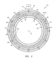
- FIG. 5 is an illustration of an exterior of the assembly portion.
- FIG. 1 is a side cutaway illustration of a geared turbine engine 10 .
- This turbine engine 10 extends along an axial centerline 12 between an upstream airflow inlet 14 and a downstream airflow exhaust 16 .
- the turbine engine 10 includes a fan section 18 , a compressor section 19 , a combustor section 20 and a turbine section 21 .
- the compressor section 19 includes a low pressure compressor (LPC) section 19 A and a high pressure compressor (HPC) section 19 B.
- the turbine section 21 includes a high pressure turbine (HPT) section 21 A and a low pressure turbine (LPT) section 21 B.
- the engine sections 18 - 21 are arranged sequentially along the centerline 12 within an engine housing 22 .
- This housing 22 includes an inner case 24 (e.g., a core case) and an outer case 26 (e.g., a fan case).
- the inner case 24 may house one or more of the engine sections 19 - 21 (e.g., an engine core), and may be housed within an inner nacelle (not shown) which provides an aerodynamic cover for the inner case 24 .
- the inner case 24 may be configured with one or more axial and/or circumferential inner case segments.
- the outer case 26 may house at least the fan section 18 , and may be housed within an outer nacelle (not shown) which provides an aerodynamic cover for the outer case 26 .
- the outer nacelle along with the outer case 26 overlaps the inner nacelle thereby defining a bypass gas path 28 radially between the nacelles.
- the outer case 26 may be configured with one or more axial and/or circumferential outer case segments.
- Each of the engine sections 18 - 19 B, 21 A and 21 B includes a respective rotor 30 - 34 .
- Each of these rotors 30 - 34 includes a plurality of rotor blades arranged circumferentially around and connected to one or more respective rotor disks.
- the rotor blades may be formed integral with or mechanically fastened, welded, brazed, adhered and/or otherwise attached to the respective rotor disk(s).
- the fan rotor 30 is connected to a gear train 36 , for example, through a fan shaft 38 .
- the gear train 36 and the LPC rotor 31 are connected to and driven by the LPT rotor 34 through a low speed shaft 39 .
- the HPC rotor 32 is connected to and driven by the HPT rotor 33 through a high speed shaft 40 .
- the shafts 38 - 40 are rotatably supported by a plurality of bearings 42 ; e.g., rolling element and/or thrust bearings. Each of these bearings 42 is connected to the engine housing 22 by at least one stationary structure such as, for example, an annular support strut.
- This air is directed through the fan section 18 and into a core gas path 42 and the bypass gas path 28 .
- the core gas path 42 extends sequentially through the engine sections 19 - 21 .
- the air within the core gas path 42 may be referred to as “core air”.
- the air within the bypass gas path 28 may be referred to as “bypass air”.
- the core air is compressed by the compressor rotors 31 and 32 and directed into a combustion chamber of a combustor 44 in the combustor section 20 .
- Fuel is injected into the combustion chamber and mixed with the compressed core air to provide a fuel-air mixture.
- This fuel air mixture is ignited and combustion products thereof flow through and sequentially cause the turbine rotors 33 and 34 to rotate.
- the rotation of the turbine rotors 33 and 34 respectively drive rotation of the compressor rotors 32 and 31 and, thus, compression of the air received from a core airflow inlet.
- the rotation of the turbine rotor 34 also drives rotation of the fan rotor 30 , which propels bypass air through and out of the bypass gas path 28 .
- the propulsion of the bypass air may account for a majority of thrust generated by the turbine engine 10 , e.g., more than seventy-five percent (75%) of engine thrust.
- the turbine engine 10 of the present disclosure is not limited to the foregoing exemplary thrust ratio.
- FIG. 2 illustrates an assembly 46 for the turbine engine 10 .
- This turbine engine assembly 46 includes a turbine engine case 48 , a rotor 50 , a blade outer air seal 52 (“BOAS”) and a tip clearance control system 54 .
- BOAS blade outer air seal
- a blade outer air seal may also be referred to as a shroud.
- the turbine engine case 48 may be configured as or part of the inner case 24 .
- the turbine engine case 48 for example, may be configured as an axial tubular segment of the inner case 24 for housing some or all of the HPT rotor 33 .
- the rotor 50 may be configured as or included in one of the rotors 30 - 34 ; e.g., the HPT rotor 33 .
- This rotor 50 includes a rotor disk 56 and a set of rotor blades 58 .
- the rotor blades 58 are arranged circumferentially around and connected to the rotor disk 56 .
- Each of the rotor blades 58 extends radially out from the rotor disk 56 to a respective rotor blade tip 60 .
- the blade outer air seal 52 circumscribes the rotor 50 and is housed radially within the turbine engine case 48 .
- the blade outer air seal 52 is configured to reduce or eliminate gas leakage across the tips 60 of the rotor blades 58 .
- the blade outer air seal 52 may be configured from or include abradable material. This abradable material, when contacted by one or more of the tips 60 during turbine engine 10 operation, may abrade to prevent damage to those rotor blades 58 as well as enabling provision of little to no gaps radially between the tips 60 and an inner surface 62 of the blade outer air seal 52 .
- the blade outer air seal 52 includes a plurality of blade outer air seal (“BOAS”) segments 64 .
- BOAS segments 64 are arranged in an annular array about the centerline 12 and the rotor 50 .
- Each of the BOAS segments 64 may have an arcuate geometry that extends partially about the centerline 12 from, for example, about one degree (1°) to about twelve degrees (12°).
- the present disclosure is not limited to the foregoing exemplary blade outer air seal or BOAS segment configurations.
- one or more of the BOAS segments 64 may have an arcuate geometry that extends more than twelve degrees.
- the tip clearance control system 54 includes a plurality of rocker arms 66 , a plurality of linkages 68 and an actuation device 70 .
- the rocker arms 66 are arranged in an array circumferentially around the centerline 12 and a radial exterior of the turbine engine case 48 . Referring to FIG. 3 , each of the rocker arms 66 is pivotally connected to the turbine engine case 48 .
- Each of the rocker arms 66 may be pivotally connected to a respective rocker arm mount 72 by a pin or shaft 74 , where the rocker arm mount 72 is mounted (directly or indirectly) to the turbine engine case 48 by one or more fasteners 76 ; see FIG. 5 .
- each of the rocker arms 66 includes a base 78 that is pivotally attached to the respective rocker arm mount 72 .
- Each of the rocker arms 66 also includes a linkage arm 80 and an actuator arm 82 .
- Each of these arms 80 and 82 projects from the base 78 .
- the linkage arm 80 of FIG. 3 projects substantially axially (relative to the centerline 12 ) from the base 78 .
- the actuator arm 82 of FIG. 3 projects substantially radially outward (relative to the centerline 12 ) from the base 78 .
- the actuator arm 82 may be clocked from the linkage arm 80 by between, for example, between about eighty-five degrees (85°) and about ninety-five degrees (95°); e.g., about ninety degrees (90°) such that the arms 80 and 82 are perpendicular to one another.
- the present disclosure is not limited to the foregoing exemplary rocker arm orientations.
- the linkage arm 80 may include an aperture such as a channel 84 .
- This channel 84 extends radially through the linkage arm 80 .
- the channel 84 also extends axially into the linkage arm 80 from a distal end 86 thereof. The channel 84 thereby provides the linkage arm 80 with a forked end configuration.
- the actuator arm 82 may include a slide block 88 .
- This slide block 88 has a tapered thickness which changes along a lateral (e.g., circumferential or tangential) width 90 (see FIG. 4 ) of the slide block 88 . More particularly, one end 92 of the slide block 88 projects axially beyond (e.g., aft or forward of) the other end 94 of the slide block 88 , as best seen in FIG. 5 .
- the linkages 68 are arranged in an array circumferentially around the centerline 12 and the blade outer air seal 52 .
- a radial inner end of each of linkages 68 is connected (directly or indirectly) to a respective one of the BOAS segments 64 .
- a radial outer end of each of the linkages 68 is connected to a respective one of the rocker arms 66 .
- the linkage arm 80 of FIGS. 3 and 4 include a shaft 96 and a head 98 .
- the shaft 96 extends radially away from the respective BOAS segment 64 , through an aperture 100 in the turbine engine case 48 and the channel 84 , and to the head 98 .
- the head 98 is radially engaged (e.g., abutted against and contacting) the linkage arm 80 .
- the head 98 may be configured to substantially prevent or otherwise limit rotation of the shaft 96 about an axis thereof.
- a bushing 102 may be configured within the aperture 100 and mated with the shaft 96 to substantially prevent or otherwise limit rocking (e.g., lateral and/or axial movement) of the shaft 96 . In this manner, the linkage 68 is substantially constrained to radial translation as described below.
- the actuation device 70 includes a rotatable actuation ring 104 , a plurality of slide blocks 106 and an actuator 108 (see FIG. 2 ).
- This actuator 108 is configured to laterally move (e.g., circumferential rotate) the actuation ring 104 about the centerline 12 .
- the actuator 108 may be configured as, but is not limited to, any type of electrical, hydraulic or other motor.
- the actuation ring 104 circumscribes the centerline 12 and the radial exterior of the turbine engine case 48 .
- the actuation ring 104 is mated with one or more supports 110 , which are mounted to the turbine engine case 48 . These supports 110 may guide circumferential rotation of the actuation ring 104 .
- the slide blocks 106 are arranged in an array circumferentially around the centerline 12 and the turbine engine case 48 .
- Each of the slide blocks 106 is configured axially between the actuation ring 104 and a respective one of the actuator arms 82 .
- each of the slide blocks 106 may be configured as part of (e.g., formed integrally/monolithically with) or otherwise connected (e.g., mechanically fastened, bonded and/or otherwise attached) to the actuation ring 104 as well as axially engage (e.g., laterally slidably contact) a respective one of the slide blocks 88 .
- Each slide block 106 has a tapered thickness which changes along a lateral (e.g., circumferential or tangential) width 112 of the slide block 106 . More particularly, one end 114 of the slide block 106 projects axially beyond (e.g., forward or aft of) the other end 116 of the slide block 106 , as best seen in FIG. 5 . It is worth noting, corresponding slide blocks 88 and 106 are tapered in opposite directions. In this manner, circumferential movement of the actuation ring 104 may axially move the actuator arms 82 . For example, counter-clockwise rotation (e.g., movement towards a left-hand-side of the page) of the actuation ring 104 of FIGS.
- counter-clockwise rotation e.g., movement towards a left-hand-side of the page
- one or more of the system 46 components may undergo thermally distortion; e.g., expand, contract, warp, etc.
- the different components may be subject to varying degrees of distortion depending upon their proximity to the core gas path 42 .
- the tip clearance control system 54 is operated to maintain a minimum (or no) gap between the tips 60 of the rotor blades 58 and the blade outer air seal 52 .
- the actuator 108 may rotate the actuation ring 104 clockwise and thereby axially move the actuator arms 82 towards the ring 104 and radially move the linkage arms 80 towards the turbine engine case 48 .
- the movement of the linkage arms 80 enable the linkages 68 and the BOAS segments 64 to move radially inwards towards the tips 60 .
- typically air pressure between the turbine engine case 48 and the BOAS segments 64 is greater than air pressure within the core gas path 42 which provides a motive force for pushing the BOAS segments 64 radially inward.
- the actuator 108 may rotate the actuation ring 104 counter-clockwise and thereby axially move the actuator arms 82 away from the ring 104 and radially move the linkage arms 80 away from the turbine engine case 48 .
- the linkage arms 80 may in turn move the linkages 68 and, thus, the BOAS segments 64 radially outward.
- the components of the tip clearance control system 54 may also be subject to varying degrees of thermal distortion and, thus, relative movement therebetween.
- the rocker arms 66 may move radially relative to the actuation device 70 due to thermal distortion.
- such relative movement may also cause movement of attached BOAS segments as described above.
- the slide blocks 88 of the present disclosure in contrast, may slide radially against the slide blocks 106 without causing rotation of the rocker arms 66 .
- the tip clearance control system 54 of the present disclosure therefore may not be subject to varying operability as components thereof are subject to different thermal distortions.
- the BOAS segments 64 described above and illustrated in the drawings are discloses as being uniquely associated with a single one of the linkages 68 and a single one of the rocker arms 66 .
- one or more of the BOAS segments 64 may be connected to two or more linkages 68 and thus operatively coupled with two or more rocker arms 66 .
- each of the slide blocks 106 may be substantially the same. In this manner, each of the BOAS segments 64 may move approximately an equal radial distance. In other embodiments, the slope of at least one of the slide blocks 106 may be different than the slope of another one of the slide blocks. In this manner, one or more of the BOAS segments 64 may move a different radial distance than at least one other BOAS segment 64 .
- Such a configuration may be beneficial where the case and/or other components asymmetrically deform during operation. Such asymmetrically deformation may be caused by positioning turbine cooling pipes around the circumference of the turbine engine.
- the turbine engine assembly 46 may be included in various turbine engines other than the one described above.
- the turbine engine assembly 46 may be included in a geared turbine engine where a gear train connects one or more shafts to one or more rotors in a fan section, a compressor section and/or any other engine section.
- the turbine engine assembly 46 may be included in a turbine engine configured without a gear train.
- the turbine engine assembly 46 may be included in a geared or non-geared turbine engine configured with a single spool, with two spools (e.g., see FIG. 1 ), or with more than two spools.
- the turbine engine may be configured as a turbofan engine, a turbojet engine, a propfan engine, a pusher fan engine or any other type of turbine engine. It is also worth noting the turbine engine assembly 46 may be included in turbine engines other than those configured for an aircraft (e.g., airplane or helicopter) propulsion system. The turbine engine assembly 46 , for example, may be configured for an industrial gas turbine engine. The present invention therefore is not limited to any particular types or configurations of turbine engines.
Landscapes
- Engineering & Computer Science (AREA)
- Mechanical Engineering (AREA)
- General Engineering & Computer Science (AREA)
- Turbine Rotor Nozzle Sealing (AREA)
Abstract
Description
Claims (20)
Priority Applications (2)
| Application Number | Priority Date | Filing Date | Title |
|---|---|---|---|
| US14/731,140 US9784117B2 (en) | 2015-06-04 | 2015-06-04 | Turbine engine tip clearance control system with rocker arms |
| EP16163706.1A EP3106624B1 (en) | 2015-06-04 | 2016-04-04 | Turbine engine tip clearance control system with rocker arms |
Applications Claiming Priority (1)
| Application Number | Priority Date | Filing Date | Title |
|---|---|---|---|
| US14/731,140 US9784117B2 (en) | 2015-06-04 | 2015-06-04 | Turbine engine tip clearance control system with rocker arms |
Publications (2)
| Publication Number | Publication Date |
|---|---|
| US20160356169A1 US20160356169A1 (en) | 2016-12-08 |
| US9784117B2 true US9784117B2 (en) | 2017-10-10 |
Family
ID=55650350
Family Applications (1)
| Application Number | Title | Priority Date | Filing Date |
|---|---|---|---|
| US14/731,140 Active 2035-10-22 US9784117B2 (en) | 2015-06-04 | 2015-06-04 | Turbine engine tip clearance control system with rocker arms |
Country Status (2)
| Country | Link |
|---|---|
| US (1) | US9784117B2 (en) |
| EP (1) | EP3106624B1 (en) |
Cited By (6)
| Publication number | Priority date | Publication date | Assignee | Title |
|---|---|---|---|---|
| US11008882B2 (en) * | 2019-04-18 | 2021-05-18 | Rolls-Royce North American Technologies Inc. | Blade tip clearance assembly |
| US11015475B2 (en) | 2018-12-27 | 2021-05-25 | Rolls-Royce Corporation | Passive blade tip clearance control system for gas turbine engine |
| US11092032B2 (en) * | 2018-08-28 | 2021-08-17 | Pratt & Whitney Canada Corp. | Variable vane actuating system |
| US11092167B2 (en) * | 2018-08-28 | 2021-08-17 | Pratt & Whitney Canada Corp. | Variable vane actuating system |
| US11105338B2 (en) | 2016-05-26 | 2021-08-31 | Rolls-Royce Corporation | Impeller shroud with slidable coupling for clearance control in a centrifugal compressor |
| US11371380B2 (en) | 2020-12-01 | 2022-06-28 | Pratt & Whitney Canada Corp. | Variable guide vane assembly and vane arms therefor |
Families Citing this family (2)
| Publication number | Priority date | Publication date | Assignee | Title |
|---|---|---|---|---|
| FR3065745B1 (en) * | 2017-04-27 | 2019-12-27 | Safran Aircraft Engines | AIRCRAFT TURBOMACHINE STATOR |
| KR102316629B1 (en) * | 2020-06-23 | 2021-10-25 | 두산중공업 주식회사 | Turbine blade tip clearance control apparatus and gas turbine comprising the same |
Citations (25)
| Publication number | Priority date | Publication date | Assignee | Title |
|---|---|---|---|---|
| US4332523A (en) | 1979-05-25 | 1982-06-01 | Teledyne Industries, Inc. | Turbine shroud assembly |
| GB2099515A (en) | 1981-05-29 | 1982-12-08 | Rolls Royce | Shroud clearance control on a gas turbine engine |
| US5018942A (en) | 1989-09-08 | 1991-05-28 | General Electric Company | Mechanical blade tip clearance control apparatus for a gas turbine engine |
| US5035573A (en) | 1990-03-21 | 1991-07-30 | General Electric Company | Blade tip clearance control apparatus with shroud segment position adjustment by unison ring movement |
| US5049033A (en) | 1990-02-20 | 1991-09-17 | General Electric Company | Blade tip clearance control apparatus using cam-actuated shroud segment positioning mechanism |
| US5054997A (en) | 1989-11-22 | 1991-10-08 | General Electric Company | Blade tip clearance control apparatus using bellcrank mechanism |
| US5056988A (en) | 1990-02-12 | 1991-10-15 | General Electric Company | Blade tip clearance control apparatus using shroud segment position modulation |
| US5096375A (en) | 1989-09-08 | 1992-03-17 | General Electric Company | Radial adjustment mechanism for blade tip clearance control apparatus |
| US5104287A (en) | 1989-09-08 | 1992-04-14 | General Electric Company | Blade tip clearance control apparatus for a gas turbine engine |
| US5228828A (en) | 1991-02-15 | 1993-07-20 | General Electric Company | Gas turbine engine clearance control apparatus |
| US5362202A (en) | 1992-10-07 | 1994-11-08 | Societe Nationale D'etude Et De Construction De Moteurs D'aviation "Snecma" | Turbomachine equipped with means for adjusting the play between the stator blades and the rotor of a compressor |
| US5545007A (en) | 1994-11-25 | 1996-08-13 | United Technologies Corp. | Engine blade clearance control system with piezoelectric actuator |
| US20060013683A1 (en) | 2004-07-15 | 2006-01-19 | Rolls-Royce Plc. | Spacer arrangement |
| US20070020095A1 (en) | 2005-07-01 | 2007-01-25 | Dierksmeier Douglas D | Apparatus and method for active control of blade tip clearance |
| WO2009067992A2 (en) * | 2007-11-26 | 2009-06-04 | Mtu Aero Engines Gmbh | Active gap regulating device for a rotor housing |
| US20120063884A1 (en) | 2009-05-28 | 2012-03-15 | Mtu Aero Engines Gmbh | Clearance control system, turbomachine and method for adjusting a running clearance between a rotor and a casing of a turbomachine |
| US8376691B2 (en) | 2007-01-20 | 2013-02-19 | Mtu Aero Engines Gmbh | Turbo engine |
| US8434997B2 (en) | 2007-08-22 | 2013-05-07 | United Technologies Corporation | Gas turbine engine case for clearance control |
| US8734090B2 (en) | 2009-02-16 | 2014-05-27 | Rolls-Royce Plc | Combination of mechanical actuator and case cooling apparatus |
| US20140212262A1 (en) | 2012-12-20 | 2014-07-31 | United Technologies Corporation | Variable outer air seal support |
| US20140271147A1 (en) | 2013-03-14 | 2014-09-18 | Rolls-Royce Corporation | Blade track assembly with turbine tip clearance control |
| WO2014160953A1 (en) | 2013-03-28 | 2014-10-02 | United Technologies Corporation | Movable air seal for gas turbine engine |
| US8934997B2 (en) | 2006-09-12 | 2015-01-13 | Sonos, Inc. | Controlling and manipulating groupings in a multi-zone media system |
| US20150218959A1 (en) * | 2014-02-03 | 2015-08-06 | General Electric Company | Variable clearance mechanism for use in a turbine engine and method of assembly |
| US20160265380A1 (en) | 2013-10-04 | 2016-09-15 | United Technologies Corporation | Gas turbine engine ramped rapid response clearance control system |
-
2015
- 2015-06-04 US US14/731,140 patent/US9784117B2/en active Active
-
2016
- 2016-04-04 EP EP16163706.1A patent/EP3106624B1/en active Active
Patent Citations (25)
| Publication number | Priority date | Publication date | Assignee | Title |
|---|---|---|---|---|
| US4332523A (en) | 1979-05-25 | 1982-06-01 | Teledyne Industries, Inc. | Turbine shroud assembly |
| GB2099515A (en) | 1981-05-29 | 1982-12-08 | Rolls Royce | Shroud clearance control on a gas turbine engine |
| US5018942A (en) | 1989-09-08 | 1991-05-28 | General Electric Company | Mechanical blade tip clearance control apparatus for a gas turbine engine |
| US5096375A (en) | 1989-09-08 | 1992-03-17 | General Electric Company | Radial adjustment mechanism for blade tip clearance control apparatus |
| US5104287A (en) | 1989-09-08 | 1992-04-14 | General Electric Company | Blade tip clearance control apparatus for a gas turbine engine |
| US5054997A (en) | 1989-11-22 | 1991-10-08 | General Electric Company | Blade tip clearance control apparatus using bellcrank mechanism |
| US5056988A (en) | 1990-02-12 | 1991-10-15 | General Electric Company | Blade tip clearance control apparatus using shroud segment position modulation |
| US5049033A (en) | 1990-02-20 | 1991-09-17 | General Electric Company | Blade tip clearance control apparatus using cam-actuated shroud segment positioning mechanism |
| US5035573A (en) | 1990-03-21 | 1991-07-30 | General Electric Company | Blade tip clearance control apparatus with shroud segment position adjustment by unison ring movement |
| US5228828A (en) | 1991-02-15 | 1993-07-20 | General Electric Company | Gas turbine engine clearance control apparatus |
| US5362202A (en) | 1992-10-07 | 1994-11-08 | Societe Nationale D'etude Et De Construction De Moteurs D'aviation "Snecma" | Turbomachine equipped with means for adjusting the play between the stator blades and the rotor of a compressor |
| US5545007A (en) | 1994-11-25 | 1996-08-13 | United Technologies Corp. | Engine blade clearance control system with piezoelectric actuator |
| US20060013683A1 (en) | 2004-07-15 | 2006-01-19 | Rolls-Royce Plc. | Spacer arrangement |
| US20070020095A1 (en) | 2005-07-01 | 2007-01-25 | Dierksmeier Douglas D | Apparatus and method for active control of blade tip clearance |
| US8934997B2 (en) | 2006-09-12 | 2015-01-13 | Sonos, Inc. | Controlling and manipulating groupings in a multi-zone media system |
| US8376691B2 (en) | 2007-01-20 | 2013-02-19 | Mtu Aero Engines Gmbh | Turbo engine |
| US8434997B2 (en) | 2007-08-22 | 2013-05-07 | United Technologies Corporation | Gas turbine engine case for clearance control |
| WO2009067992A2 (en) * | 2007-11-26 | 2009-06-04 | Mtu Aero Engines Gmbh | Active gap regulating device for a rotor housing |
| US8734090B2 (en) | 2009-02-16 | 2014-05-27 | Rolls-Royce Plc | Combination of mechanical actuator and case cooling apparatus |
| US20120063884A1 (en) | 2009-05-28 | 2012-03-15 | Mtu Aero Engines Gmbh | Clearance control system, turbomachine and method for adjusting a running clearance between a rotor and a casing of a turbomachine |
| US20140212262A1 (en) | 2012-12-20 | 2014-07-31 | United Technologies Corporation | Variable outer air seal support |
| US20140271147A1 (en) | 2013-03-14 | 2014-09-18 | Rolls-Royce Corporation | Blade track assembly with turbine tip clearance control |
| WO2014160953A1 (en) | 2013-03-28 | 2014-10-02 | United Technologies Corporation | Movable air seal for gas turbine engine |
| US20160265380A1 (en) | 2013-10-04 | 2016-09-15 | United Technologies Corporation | Gas turbine engine ramped rapid response clearance control system |
| US20150218959A1 (en) * | 2014-02-03 | 2015-08-06 | General Electric Company | Variable clearance mechanism for use in a turbine engine and method of assembly |
Non-Patent Citations (3)
| Title |
|---|
| EP search report for EP16163680.8 dated Nov. 18, 2016. |
| EP search report for EP16163706.1 dated Nov. 18, 2016. |
| Office action for U.S. Appl. No. 14/731,155 dated Dec. 22, 2017. |
Cited By (6)
| Publication number | Priority date | Publication date | Assignee | Title |
|---|---|---|---|---|
| US11105338B2 (en) | 2016-05-26 | 2021-08-31 | Rolls-Royce Corporation | Impeller shroud with slidable coupling for clearance control in a centrifugal compressor |
| US11092032B2 (en) * | 2018-08-28 | 2021-08-17 | Pratt & Whitney Canada Corp. | Variable vane actuating system |
| US11092167B2 (en) * | 2018-08-28 | 2021-08-17 | Pratt & Whitney Canada Corp. | Variable vane actuating system |
| US11015475B2 (en) | 2018-12-27 | 2021-05-25 | Rolls-Royce Corporation | Passive blade tip clearance control system for gas turbine engine |
| US11008882B2 (en) * | 2019-04-18 | 2021-05-18 | Rolls-Royce North American Technologies Inc. | Blade tip clearance assembly |
| US11371380B2 (en) | 2020-12-01 | 2022-06-28 | Pratt & Whitney Canada Corp. | Variable guide vane assembly and vane arms therefor |
Also Published As
| Publication number | Publication date |
|---|---|
| EP3106624A1 (en) | 2016-12-21 |
| US20160356169A1 (en) | 2016-12-08 |
| EP3106624B1 (en) | 2019-10-09 |
Similar Documents
| Publication | Publication Date | Title |
|---|---|---|
| US9784117B2 (en) | Turbine engine tip clearance control system with rocker arms | |
| EP3106623B1 (en) | Turbine engine tip clearance control system with lateral translatable slide block | |
| US10815815B2 (en) | Actuator for gas turbine engine blade outer air seal | |
| US10316686B2 (en) | High response turbine tip clearance control system | |
| US10550708B2 (en) | Floating, non-contact seal with at least three beams | |
| US10233763B2 (en) | Seal assembly for turbine engine component | |
| EP2984298B1 (en) | Gas turbine engine rapid response clearance control system with air seal segment interface | |
| US10408080B2 (en) | Tailored thermal control system for gas turbine engine blade outer air seal array | |
| US10316683B2 (en) | Gas turbine engine blade outer air seal thermal control system | |
| US9915163B2 (en) | Cam-follower active clearance control | |
| US9915162B2 (en) | Flexible feather seal for blade outer air seal gas turbine engine rapid response clearance control system | |
| US20160369644A1 (en) | Gas turbine rapid response clearance control system with annular piston | |
| US10132187B2 (en) | Clearance control assembly | |
| US10815884B2 (en) | Gas turbine engine de-icing system | |
| US10161260B2 (en) | Vane lever arm for a variable area vane arrangement | |
| US9915228B2 (en) | Air with integral spring for a gas turbine engine exhaust drive | |
| US11814989B2 (en) | Vane array structure for a hot section of a gas turbine engine | |
| US10746041B2 (en) | Shroud and shroud assembly process for variable vane assemblies | |
| US10030533B2 (en) | Flanged bushing for variable vane |
Legal Events
| Date | Code | Title | Description |
|---|---|---|---|
| AS | Assignment |
Owner name: UNITED TECHNOLOGIES CORPORATION, CONNECTICUT Free format text: ASSIGNMENT OF ASSIGNORS INTEREST;ASSIGNORS:DUGUAY, BRIAN;DAVIS, TIMOTHY M.;REEL/FRAME:036818/0087 Effective date: 20150604 |
|
| STCF | Information on status: patent grant |
Free format text: PATENTED CASE |
|
| CC | Certificate of correction | ||
| AS | Assignment |
Owner name: RAYTHEON TECHNOLOGIES CORPORATION, MASSACHUSETTS Free format text: CHANGE OF NAME;ASSIGNOR:UNITED TECHNOLOGIES CORPORATION;REEL/FRAME:054062/0001 Effective date: 20200403 |
|
| AS | Assignment |
Owner name: RAYTHEON TECHNOLOGIES CORPORATION, CONNECTICUT Free format text: CORRECTIVE ASSIGNMENT TO CORRECT THE AND REMOVE PATENT APPLICATION NUMBER 11886281 AND ADD PATENT APPLICATION NUMBER 14846874. TO CORRECT THE RECEIVING PARTY ADDRESS PREVIOUSLY RECORDED AT REEL: 054062 FRAME: 0001. ASSIGNOR(S) HEREBY CONFIRMS THE CHANGE OF ADDRESS;ASSIGNOR:UNITED TECHNOLOGIES CORPORATION;REEL/FRAME:055659/0001 Effective date: 20200403 |
|
| MAFP | Maintenance fee payment |
Free format text: PAYMENT OF MAINTENANCE FEE, 4TH YEAR, LARGE ENTITY (ORIGINAL EVENT CODE: M1551); ENTITY STATUS OF PATENT OWNER: LARGE ENTITY Year of fee payment: 4 |
|
| AS | Assignment |
Owner name: RTX CORPORATION, CONNECTICUT Free format text: CHANGE OF NAME;ASSIGNOR:RAYTHEON TECHNOLOGIES CORPORATION;REEL/FRAME:064714/0001 Effective date: 20230714 |