US9779516B2 - Method and device for predicting an image portion for encoding or decoding of an image - Google Patents
Method and device for predicting an image portion for encoding or decoding of an image Download PDFInfo
- Publication number
- US9779516B2 US9779516B2 US13/939,507 US201313939507A US9779516B2 US 9779516 B2 US9779516 B2 US 9779516B2 US 201313939507 A US201313939507 A US 201313939507A US 9779516 B2 US9779516 B2 US 9779516B2
- Authority
- US
- United States
- Prior art keywords
- image portion
- intra prediction
- samples
- image
- displacement
- Prior art date
- Legal status (The legal status is an assumption and is not a legal conclusion. Google has not performed a legal analysis and makes no representation as to the accuracy of the status listed.)
- Active, expires
Links
Images


Classifications
-
- G—PHYSICS
- G06—COMPUTING OR CALCULATING; COUNTING
- G06T—IMAGE DATA PROCESSING OR GENERATION, IN GENERAL
- G06T9/00—Image coding
- G06T9/004—Predictors, e.g. intraframe, interframe coding
-
- H—ELECTRICITY
- H04—ELECTRIC COMMUNICATION TECHNIQUE
- H04N—PICTORIAL COMMUNICATION, e.g. TELEVISION
- H04N19/00—Methods or arrangements for coding, decoding, compressing or decompressing digital video signals
- H04N19/10—Methods or arrangements for coding, decoding, compressing or decompressing digital video signals using adaptive coding
- H04N19/102—Methods or arrangements for coding, decoding, compressing or decompressing digital video signals using adaptive coding characterised by the element, parameter or selection affected or controlled by the adaptive coding
- H04N19/103—Selection of coding mode or of prediction mode
- H04N19/11—Selection of coding mode or of prediction mode among a plurality of spatial predictive coding modes
-
- H—ELECTRICITY
- H04—ELECTRIC COMMUNICATION TECHNIQUE
- H04N—PICTORIAL COMMUNICATION, e.g. TELEVISION
- H04N19/00—Methods or arrangements for coding, decoding, compressing or decompressing digital video signals
- H04N19/10—Methods or arrangements for coding, decoding, compressing or decompressing digital video signals using adaptive coding
- H04N19/134—Methods or arrangements for coding, decoding, compressing or decompressing digital video signals using adaptive coding characterised by the element, parameter or criterion affecting or controlling the adaptive coding
- H04N19/154—Measured or subjectively estimated visual quality after decoding, e.g. measurement of distortion
-
- H—ELECTRICITY
- H04—ELECTRIC COMMUNICATION TECHNIQUE
- H04N—PICTORIAL COMMUNICATION, e.g. TELEVISION
- H04N19/00—Methods or arrangements for coding, decoding, compressing or decompressing digital video signals
- H04N19/10—Methods or arrangements for coding, decoding, compressing or decompressing digital video signals using adaptive coding
- H04N19/169—Methods or arrangements for coding, decoding, compressing or decompressing digital video signals using adaptive coding characterised by the coding unit, i.e. the structural portion or semantic portion of the video signal being the object or the subject of the adaptive coding
- H04N19/17—Methods or arrangements for coding, decoding, compressing or decompressing digital video signals using adaptive coding characterised by the coding unit, i.e. the structural portion or semantic portion of the video signal being the object or the subject of the adaptive coding the unit being an image region, e.g. an object
- H04N19/176—Methods or arrangements for coding, decoding, compressing or decompressing digital video signals using adaptive coding characterised by the coding unit, i.e. the structural portion or semantic portion of the video signal being the object or the subject of the adaptive coding the unit being an image region, e.g. an object the region being a block, e.g. a macroblock
-
- H—ELECTRICITY
- H04—ELECTRIC COMMUNICATION TECHNIQUE
- H04N—PICTORIAL COMMUNICATION, e.g. TELEVISION
- H04N19/00—Methods or arrangements for coding, decoding, compressing or decompressing digital video signals
- H04N19/50—Methods or arrangements for coding, decoding, compressing or decompressing digital video signals using predictive coding
- H04N19/593—Methods or arrangements for coding, decoding, compressing or decompressing digital video signals using predictive coding involving spatial prediction techniques
-
- H—ELECTRICITY
- H04—ELECTRIC COMMUNICATION TECHNIQUE
- H04N—PICTORIAL COMMUNICATION, e.g. TELEVISION
- H04N19/00—Methods or arrangements for coding, decoding, compressing or decompressing digital video signals
- H04N19/60—Methods or arrangements for coding, decoding, compressing or decompressing digital video signals using transform coding
- H04N19/61—Methods or arrangements for coding, decoding, compressing or decompressing digital video signals using transform coding in combination with predictive coding
Definitions
- the invention relates to a method and a device for predicting an image portion for encoding or decoding of an image.
- the invention further relates to a method and a device for encoding or decoding an image portion.
- the invention relates more specifically to intra mode coding in the High Efficiency Video Coding (HEVC) standard under development.
- HEVC High Efficiency Video Coding
- Video applications are continuously moving towards higher resolution.
- a large quantity of video material is distributed in digital form over broadcast channels, digital networks and packaged media, with a continuous evolution towards higher quality and resolution (e.g. higher number of pixels per frame, higher frame rate, higher bit-depth or extended color gamut).
- This technology evolution puts higher pressure on the distribution networks that are already facing difficulties in bringing HDTV resolution and high data rates economically to the end user. Consequently, any further data rate increases will put additional pressure on the networks.
- ITU-T and ISO/MP a new video coding standard project, called High Efficiency Video Coding (HEVC) was launched.
- HEVC High Efficiency Video Coding
- the HEVC codec design is similar to that of previous so-called block-based hybrid transform codecs such as H.263, H.264, MPEG-1, MPEG-2, MPEG-4, SVC.
- Video compression algorithms such as those standardized by standardization bodies ITU, ISO and SMPTE use the spatial and temporal redundancies of the images in order to generate data bit streams of reduced size compared with the video sequences. Such compression techniques render the transmission and/or storage of the video sequences more effective.
- FIG. 1 shows an example of an image coding structure used in HEVC.
- a video sequence is made up of a sequence of digital images 101 represented by one or more matrices the coefficients of which represent pixels.
- An image 101 is made up of one or more slices 102 .
- a slice may be part of the image or, in some cases, the entire image.
- Slices are divided into non-overlapping blocks, typically referred to as Largest Coding Units (LCUs) 103 ; LCUs are generally blocks of size 64 pixels ⁇ 64 pixels.
- LCUs are generally blocks of size 64 pixels ⁇ 64 pixels.
- Each LCU may in turn be iteratively divided into smaller variable size Coding Units (CUs) 104 using a quadtree decomposition.
- each block of an image being processed is predicted spatially by an “Intra” predictor (so-called “Intra” coding mode), or temporally by an “Inter” predictor (so-called “Inter” coding mode).
- the predictor (Intra predictor) used for the current block being coded is a block of pixels constructed from information already encoded or decoded (depending on whether the prediction process is applied at the encoder end or the decoder end) of the current image.
- a CU may thus be coded according to an intra coding mode, (samples of the CU are spatially predicted from neighboring samples of the CU) or to an inter coding mode (samples of the CU are temporally predicted from samples of previously coded slices).
- the residual signal between the original CU samples and the prediction CU samples is generated. This residual is then coded after having applied transformation and quantization processes.
- intra coding involves deriving an intra prediction block from reconstructed neighboring samples 201 of the block to be encoded or decoded (depending on whether the prediction process is applied at the encoder end or at the decoder end), as illustrated schematically in FIG. 2A .
- intra mode coding makes use of two neighbouring CUs that have already been coded or decoded, namely the Top and Left CUs 203 and 204 .
- intra mode coding multiple prediction modes are supported.
- a CU is intra coded, its related intra prediction mode is coded in order to inform a decoder how to decode the coded CU.
- a first type corresponds to non-directional intra prediction modes and contains two modes: a Planar mode and a DC mode.
- a second type corresponds to directional intra prediction modes. Up to 33 directional modes are supported.
- FIG. 3 depicts the number of different considered modes in a recent design.
- samples inside the predicted block are equal to the mean of the neighboring samples.
- neighboring samples values are smoothly propagated inside the prediction block, using a linear variation.
- the neighboring samples values are propagated along a given angular direction.
- the prediction process operates in two steps. First a row of reference samples refMain[p] (p being the position in the refMain table) is built from the neighbouring samples and the angular direction. Then these reference samples are used to predict the samples inside the block pred[x,y] (x,y being the coordinates in the block) along the angular direction.
- the refMain row is either horizontal or vertical depending on the direction. When the direction is below the diagonal left direction (numbered as 18 in FIG. 3 ), the refMain row is vertical. Otherwise the refMain row is horizontal. For instance in FIG. 4 , when the direction 402 is below the diagonal left direction 401 , the reference samples refMain[p] 403 ) are built from the top row of the block and from the left column of the block projected along the horizontal axis. The horizontal refMain[p] table is then used to derive the block prediction pred[x,y] 404 . When the direction 405 is above the diagonal left direction 406 , the reference samples remain[p] 407 are built from the left column of the block and from the top row of the block projected along the vertical axis. The vertical refMain[p] table is then used to derive the block prediction pred[x,y] 408 .
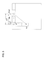
- Pred[ x,y ] ((32 ⁇ i Fact)*ref[ idx ]+ i Fact*ref[ idx +1]+16)>>5 (2) where idx and iFact are the integer and fractional parts of (y ⁇ +x), as shown in FIG. 5 .
- This process enables the reference samples signal to be interpolated with an accuracy of 1/32 pixel.
- the present invention has been devised to provide an improved intra prediction process.
- embodiments of the invention seek to address a loss in coding efficiency induced by spatial misalignment of reference samples.
- the parametric displacement transformation is applied to the derived samples prior to generation of the prediction image portion.
- the intra prediction process is adapted according to the parametric displacement transformation.
- the parametric displacement transformation is applied to the generated prediction image portion.
- the direction of the parametric displacement transformation is determined from the intra prediction mode.
- the type of parametric displacement transformation is dependent upon the intra prediction mode.
- parameters of the parametric displacement transformation are determined from data of one or more encoded image portions neighbouring the image portion to be encoded.
- the parametric displacement transformation comprises a 1D displacement defined by one parameter.
- the parametric displacement transformation comprises a 2D displacement defined by two parameters
- the parametric displacement transformation comprises an affine displacement.
- data representative of the parametric displacement transformation is signalled in the bitstream into which the image portion is encoded.
- the or each derived sample is derived from encoded neighbouring image portions of the image portion to be predicted.
- derivation means for deriving samples from at least one reference image portion
- generation means for generating, from said derived samples, by the intra prediction process, at least one prediction image portion corresponding to the image portion to be predicted;
- transformation means for applying a parametric displacement transformation to at least the derived samples and/or the prediction image portion.
- the transformation means is operable to apply a parametric displacement transformation to the derived samples prior to generation of the prediction image portion.
- the generation means is operable to adapt the intra prediction process according to the parametric displacement transformation.
- the transformation means is adapted to apply the parametric displacement transformation to the generated prediction image portion.
- the transformation means is operable to determine the direction of the parametric displacement transformation from the intra prediction mode.
- the transformation means is operable to determine the type of parametric displacement transformation based on the intra prediction mode.
- the transformation means is operable to determine the parameters of the parametric displacement transformation from data of one or more encoded image portions neighbouring the image portion to be encoded.
- the transformation means is operable to apply a 1D displacement defined by one parameter.
- the transformation means is operable to apply a 2D displacement defined by two parameters
- the transformation means is operable to apply an affine displacement.
- signalling means are provided for signalling data representative of the parametric displacement transformation in the bitstream into which the image portion is encoded.
- the derivation means is operable to derive each derived sample from encoded neighbouring image portions of the image portion to be predicted.
- an encoding device for encoding an image, comprising
- an encoder for encoding image data obtained based on the at least one prediction image portion.
- a decoding device for decoding an image, comprising
- a decoder for decoding image data obtained based on the at least one prediction image portion.
- the present invention may take the form of an entirely hardware embodiment, an entirely software embodiment (including firmware, resident software, micro-code, etc.) or an embodiment combining software and hardware aspects that may all generally be referred to herein as a “circuit”, “module” or “system”.
- the present invention may take the form of a computer program product embodied in any tangible medium of expression having computer usable program code embodied in the medium.
- a tangible carrier medium may comprise a storage medium such as a floppy disk, a CD-ROM, a hard disk drive, a magnetic tape device or a solid state memory device and the like.
- a transient carrier medium may include a signal such as an electrical signal, an electronic signal, an optical signal, an acoustic signal, a magnetic signal or an electromagnetic signal, e.g. a microwave or RF signal.
- FIG. 1 illustrates an example of image coding structure as defined in the HEVC specification.
- FIG. 2 schematically illustrates image portions of image in an intra prediction coding process.
- FIG. 3 shows various prediction modes considered in HEVC with their corresponding mode numbers.
- FIG. 4 schematically illustrates example for building an array of reference samples HEVC.
- FIG. 5 schematically illustrates a process of angular prediction in HEVC.
- FIGS. 6A to 6C illustrate a method of predicting an image portion according to a first embodiment of the invention.
- FIGS. 7A and 7B illustrate a method of predicting an image portion according to a second embodiment of the invention.
- FIG. 8 illustrates a method of predicting an image portion according to a third embodiment of the invention.
- FIG. 9 schematically illustrates the samples that are used to infer the transformation parameters at the encoder and decoder end according to one or more embodiments of the invention.
- FIG. 10 is a schematic diagram of a wireless communication network in which one or more embodiments of the invention may be implemented.
- FIG. 11 is a schematic block diagram of a wireless communication device according to at least one embodiment of the invention.
- FIGS. 6A to 6C A method of predicting a portion of an image for encoding or decoding of an image according to a first embodiment of the invention will now be described with reference to FIGS. 6A to 6C .
- FIG. 6A is a flow chart illustrating steps of a method of predicting an image portion according to a first embodiment of the invention.
- an image portion is referred to as a block.
- the input data of the prediction process include reconstructed samples 601 Rec[x,y] surrounding a block of an image to be predicted and the intra prediction mode m 606 .
- a reference samples generation process is applied in step S 602 to build reference samples Ref[x,y] from the surrounding samples Rec[x,y] 601 by applying the intra prediction mode m 606 .
- a process for generating predicted samples is then applied in step S 603 to generate the predicted samples Pred[x,y] of the block from the reference samples Ref[x,y], using the intra prediction mode m 606 .
- a final parametric transformation process is then applied in step S 604 to the predicted samples Pred[x,y] to generate final prediction samples Pred′[x,y] 605 .
- This transformation uses input transformation parameters q 607 and, when appropriate, the intra prediction mode m 606 .
- step S 604 corresponds to a 2D affine displacement potentially combined with a translation:
- an interpolation process is applied to generate Pred[u,v].
- a bilinear interpolation process can be used, for example.
- Another possibility is to use the same interpolation filter used in the motion compensation process of HEVC (8-tap linear filter for luma samples, 4-tap linear filter for chroma samples).
- the transformation of step S 604 corresponds to a 1D translation specified by one parameter.
- the direction of the displacement can be deduced from the intra prediction mode. For instance, if the intra prediction mode is angular, and applies to a horizontal refMain row of samples, the displacement is applied in the horizontal dimension. Inversely, if the intra prediction mode is angular, and applies to a vertical refMain row of samples, the displacement is applied in the vertical dimension.
- the type of transformation of step S 604 depends on the intra mode. For instance, if the mode is non-angular, a 2D displacement applies. If the mode is angular, a 1D displacement applies.
- FIGS. 6B and 6C schematically illustrate an example of this process.
- the block being predicted as well as the reference sample rows contain samples corresponding to oriented lines. It is supposed that the intra prediction mode corresponds exactly to the angular direction of these oriented lines.
- First the prediction samples Pred[x,y] 609 of the block are generated from the reference samples Ref[x,y] 608 by directional propagation along the angular direction as illustrated in FIG. 6B .
- the displacement is applied to the predicted samples Pred[x,y] 609 , to generate the final prediction samples Pred′[x,y] 610 , that correspond to the oriented lines slightly displaced, as illustrated in FIG. 6C .
- FIGS. 7A to 7B A method of predicting a portion of an image for encoding or decoding of image according to a second embodiment of the invention will now be described with reference to FIGS. 7A to 7B .
- FIG. 7A is a flow chart illustrating steps of a method of predicting an image portion according to a second embodiment of the invention.
- the input data of the prediction process are reconstructed samples Rec[x,y] 701 surrounding the block of the image to be predicted and the intra prediction mode m 706 .
- a process for generating reference samples is applied in step S 702 to generate reference samples Ref[x,y] from the surrounding samples Rec[x,y] and using the intra prediction mode m 706 .
- a transformation process is then applied in step S 703 to the reference samples Ref[x,y] to generate a new version of reference samples Ref′[x,y].
- the transformation uses input parameters q 707 and where appropriate the intra prediction mode m 706 .
- a process for generating the predicted samples is applied using the reference samples Ref′[x,y] and the intra prediction mode m 706 to generate the predicted samples of the block.
- step S 704 corresponds to a 2D affine displacement potentially combined with a translation:
- an interpolation process is applied to generate reference samples Ref′[u,v].
- a bilinear interpolation process can be used, for example.
- Another possibility is to use the same interpolation filter used in the motion compensation process of HEVC (8-tap linear filter for luma samples, 4-tap linear filter for chroma samples).
- the transformation of step S 704 corresponds to a 1D translation specified by 1 parameter.
- the direction of the displacement can be deduced from the intra prediction mode. For instance, if the intra prediction mode is angular, and applies to horizontal refMain row, the displacement applies in the horizontal dimension. Inversely, if the intra prediction mode is angular, and applies to vertical refMain row, the displacement applies in the vertical dimension.
- the direction of the displacement can also be signaled in the bitstream. If the reference samples are stored in a 1D array (refMain[x]), the displacement is necessarily 1D and no direction needs to be signaled.
- the type of transformation of step S 704 depends on the intra mode. For instance, if the mode is non-angular, a 2D displacement applies. If the mode is angular, a 1D displacement applies.
- FIG. 7B schematically illustrates an example of this process.
- the reference samples are a 1D row, the value of these samples corresponding to oriented lines.
- the modified reference samples Ref′[x,y] 709 are obtained from reference samples Ref[x,y] 708 after having applied the transformation (1D displacement).
- Some particular embodiments of the invention can be implemented in the HEVC design directly by modifying the prediction process, in the case of a 1D displacement. As explained above, for angular prediction modes, the prediction process first generates a 1D row of reference samples refMain[x].
- a simple process can be applied to generate the angular intra prediction samples without explicitly generating a new row of reference samples ref'[x] from the original row ref[x].
- this solution is advantageous in that it avoids generating a new row of reference samples ref'[x] from the original row of reference samples ref[x] and does not add any complexity since almost the same prediction equation is used as in the default HEVC design.
- An example of such a process is illustrated in FIG. 8 .
- FIG. 8 is a flow chart illustrating steps of a method of predicting an image portion according to a third embodiment of the invention.
- the input data of the prediction process are reconstructed samples Rec[x,y] 801 surrounding the block to be predicted and the intra prediction mode m 805 .
- a process for generating samples generation is applied in step S 802 to generate reference samples RefMain[x] from the surrounding samples 801 and using the intra prediction mode m 805 .
- the modified generation process of predicted samples Pred[x,y] 804 is then applied in step S 803 to generate predicted samples Pred[x,y] 804 using the reference samples RefMain[x].
- This process also uses as input data the displacement d 806 and the intra prediction mode m 805 .
- d is not constant over the entire block and may vary with the line (or column) number.
- input parameters q are identified at the encoder end and transmitted in the bitstream for each CU, and for a set of CUs (for example, for the largest coding units—LCU—specified in HEVC).
- the decoder explicitly decodes these data for each CU or set of CUs.
- the estimation process of q can comprise an exhaustive rate-distortion testing of all the possible values of q.
- q is among ⁇ 1, 0, 1 ⁇ in the case of a 1D displacement.
- q is made of 6 parameters and consequently the search set is 6-dimensional.
- the translational part (parameters e and f) can be checked similarly in the set ⁇ 1, 0, 1 ⁇ .
- the affine part (parameters a, b, c and d)
- the set ⁇ 0.1, 0, 0.1 ⁇ can be used for each parameter, for instance.
- a prediction process is applied for each considered possible value of q.
- the related distortion D(m,q) compared to the original signal is measured.
- the coding cost R(m,q) of the prediction residual, and the coding parameters (coding mode m, parameters q) is computed.
- the best parameters configuration is the parameters q_opt such as D(m,q)+ ⁇ R(m,q) is minimum.
- ⁇ is the so-called lagrangian parameter, generally set at the encoder based on the quantization parameter value.
- the decoder is operable to infer the parameters q. No signaling is thus required.
- q is computed from the prediction samples of surrounding blocks and reconstructed samples.
- FIG. 9 Virtual prediction samples virt[x,y] are considered as the surrounding samples resulting from a spatial prediction applied to the surrounding blocks (using their own intra coding mode if they are intra coded, or using the mode m if they are not intra coded, or using the mode m whatever they are intra or inter coded).
- the surrounding reconstructed samples Rec[x,y] are considered. The displacement is estimated between these 2 samples sets, for instance by a classical matching algorithm.
- the encoder must perform the same process on its side, in order to generate the same parameters as the decoder.
- the encoder and decoder infer a probable value of q. Then the encoder performs the estimation of the true value of q, based on the real samples and using for instance a rate-distortion optimization among all the possible values of q. Finally the encoder transmits the difference q_diff between the estimated parameters q_est and the true parameters q_real.
- FIG. 10 illustrates a data communication system in which one or more embodiments of the invention may be implemented.
- the data communication system comprises a transmission device, in this case a server 1001 , which is operable to transmit data packets of a data stream to a receiving device, in this case a client terminal 1002 , via a data communication network 1000 .
- the data communication network 1000 may be a Wide Area Network (WAN) or a Local Area Network (LAN).
- WAN Wide Area Network
- LAN Local Area Network
- Such a network may be for example a wireless network (Wifi/802.11a or b or g), an Ethernet network, an Internet network or a mixed network composed of several different networks.
- the data communication system may be a digital television broadcast system in which the server 1001 sends the same data content to multiple clients.
- the data stream 1004 provided by the server 1001 may be composed of a bitstream representing multimedia data such as video and/or audio data. Audio and video data streams may, in some embodiments of the invention, be captured by the server 1001 using a microphone and a camera respectively. In some embodiments data streams may be stored on the server 1001 or received by the server 1001 from another data provider, or generated at the server 1001 .
- the server 1001 is provided with an encoder for encoding video and audio streams in particular to provide a compressed bitstream for transmission that is a more compact representation of the data input to the encoder.
- the compression of video data may be for example in accordance with the HEVC format or H.264/AVC format.
- the client 1002 receives the transmitted bitstream and decodes the reconstructed bitstream to reproduce video images on a display device and audio data by a loud speaker.
- an encoded video image is transmitted with a brightness component (luma) and two colour components (chroma).
- the digital representation of the video signal thus includes a luma component (Y), representative of brightness, and colour difference (or chroma) components U and V.
- FIG. 11 schematically illustrates a processing device 1100 configured to implement at least one embodiment of the present invention.
- the processing device 1100 may be a device such as a micro-computer, a workstation or a light portable device such as a smart phone and portable computer.
- the device 1100 comprises a communication bus 1113 connected to:
- the apparatus 1100 may also include the following components:
- the apparatus 1100 can be connected to various peripherals, such as for example a digital camera 1120 or a microphone 1108 , each being connected to an input/output card (not shown) so as to supply multimedia data to the apparatus 1100 .
- peripherals such as for example a digital camera 1120 or a microphone 1108 , each being connected to an input/output card (not shown) so as to supply multimedia data to the apparatus 1100 .
- the communication bus 1113 provides communication and interoperability between the various elements included in the apparatus 1100 or connected to it.
- the representation of the communication bus is not limiting and in particular the central processing unit is operable to communicate instructions to any element of the apparatus 1100 directly or by means of another element of the apparatus 1100 .
- the disk 1106 can be replaced by any information medium such as for example a compact disk (CD-ROM), rewritable or not, a ZIP disk or a memory card and, in general terms, by an information storage means that can be read by a microcomputer or by a microprocessor, integrated or not into the apparatus, possibly removable and adapted to store one or more programs whose execution enables the method of encoding a sequence of digital images and/or the method of decoding a bitstream according to the invention to be implemented.
- CD-ROM compact disk
- ZIP disk or a memory card
- an information storage means that can be read by a microcomputer or by a microprocessor, integrated or not into the apparatus, possibly removable and adapted to store one or more programs whose execution enables the method of encoding a sequence of digital images and/or the method of decoding a bitstream according to the invention to be implemented.
- the executable code may be stored either in read only memory 1107 , on the hard disk 1104 or on a removable digital medium such as for example a disk 1106 as described previously. Moreover in some embodiments, the executable code of the programs can be received by means of the communication network 1103 , via the interface 1102 , in order to be stored in one of the storage means of the apparatus 1100 before being executed, such as the hard disk 1104 .
- the central processing unit 1111 is adapted to control and direct the execution of the instructions or portions of software code of the program or programs for running methods such as encoding or decoding according to embodiments of the invention, instructions that are stored in one of the aforementioned storage means.
- the program or programs that are stored in a non-volatile memory for example on the hard disk 1104 or in the read only memory 1107 , are transferred into the random access memory 1112 , which then contains the executable code of the program or programs, as well as registers for storing the variables and parameters necessary for implementing embodiments of the invention.
- the apparatus is a programmable apparatus which uses software to implement the invention.
- the present invention may be implemented in hardware (for example, in the form of an Application Specific Integrated Circuit or ASIC).
Landscapes
- Engineering & Computer Science (AREA)
- Multimedia (AREA)
- Signal Processing (AREA)
- Physics & Mathematics (AREA)
- General Physics & Mathematics (AREA)
- Theoretical Computer Science (AREA)
- Compression Or Coding Systems Of Tv Signals (AREA)
Abstract
Description
Pred[x,y]=refMain[y·θ+x] (1)
where θ is the arc tangent of the angle corresponding to the angular direction, as shown in
Pred[x,y]=((32−iFact)*ref[idx]+iFact*ref[idx+1]+16)>>5 (2)
where idx and iFact are the integer and fractional parts of (y·θ+x), as shown in
-
- Three options are considered:
- 1. Modification of a prediction block
- 2. Modification of reference samples
- 3. Modification of a prediction process
Pred[x,y]=((32−iFact)*ref[idx]+iFact*ref[idx+1]+16)>>5 (9)
where idx and iFact are the integer and fractional parts of (y·θ+x+d). This is equivalent to displacing the reference samples by an offset value corresponding to a displacement of d, or to displace the predicted samples.
-
- a
central processing unit 1111, such as a microprocessor, denoted CPU; - a read only
memory 1107, denoted ROM, for storing computer programs for implementing embodiments of the invention; - a
random access memory 1112, denoted RAM, which may be used for storing the executable code of the method of embodiments of the invention as well as the registers adapted to record variables and parameters necessary for implementing the method of encoding a sequence of digital images and/or the method of decoding a bitstream according to embodiments of the invention; and - a
communication interface 1102 connected to a communication network 11011 over which data to be processed is transmitted or received.
- a
-
- a data storage means 1104 such as a hard disk, for storing computer programs for implementing methods of one or more embodiments of the invention and data used or produced during the implementation of one or more embodiments of the invention;
- a disk drive 1105 for a
disk 1106, the disk drive being adapted to read data from thedisk 1106 or to write data onto said disk; - a
screen 1109 for displaying data and/or serving as a graphical interface with the user, by means of akeyboard 1110 or any other pointing means.
Claims (9)
Applications Claiming Priority (2)
| Application Number | Priority Date | Filing Date | Title |
|---|---|---|---|
| GB1212423.6 | 2012-07-12 | ||
| GB1212423.6A GB2504069B (en) | 2012-07-12 | 2012-07-12 | Method and device for predicting an image portion for encoding or decoding of an image |
Publications (2)
| Publication Number | Publication Date |
|---|---|
| US20140016874A1 US20140016874A1 (en) | 2014-01-16 |
| US9779516B2 true US9779516B2 (en) | 2017-10-03 |
Family
ID=46799523
Family Applications (1)
| Application Number | Title | Priority Date | Filing Date |
|---|---|---|---|
| US13/939,507 Active 2034-11-28 US9779516B2 (en) | 2012-07-12 | 2013-07-11 | Method and device for predicting an image portion for encoding or decoding of an image |
Country Status (2)
| Country | Link |
|---|---|
| US (1) | US9779516B2 (en) |
| GB (1) | GB2504069B (en) |
Families Citing this family (7)
| Publication number | Priority date | Publication date | Assignee | Title |
|---|---|---|---|---|
| CN106604676A (en) * | 2014-07-15 | 2017-04-26 | 传感技术股份有限公司 | Integrated optical filter system with low sensitivity to high angle of incidence light for an analyte sensor |
| WO2017030418A1 (en) * | 2015-08-19 | 2017-02-23 | 엘지전자(주) | Method and device for encoding/decoding video signal by using optimized conversion based on multiple graph-based model |
| US10194170B2 (en) * | 2015-11-20 | 2019-01-29 | Mediatek Inc. | Method and apparatus for video coding using filter coefficients determined based on pixel projection phase |
| WO2018047668A1 (en) * | 2016-09-12 | 2018-03-15 | ソニー株式会社 | Image processing device and image processing method |
| CN116634181A (en) * | 2016-10-04 | 2023-08-22 | 株式会社Kt | Method for decoding and encoding images, method for transmitting image data |
| CN115442599B (en) * | 2017-10-20 | 2025-02-21 | 英迪股份有限公司 | Image encoding and decoding method and recording medium storing bit stream |
| EP3562158A1 (en) | 2018-04-27 | 2019-10-30 | InterDigital VC Holdings, Inc. | Method and apparatus for combined intra prediction modes |
Citations (9)
| Publication number | Priority date | Publication date | Assignee | Title |
|---|---|---|---|---|
| US20090196342A1 (en) | 2006-08-02 | 2009-08-06 | Oscar Divorra Escoda | Adaptive Geometric Partitioning For Video Encoding |
| US20090268810A1 (en) | 2006-09-29 | 2009-10-29 | Congxia Dai | Geometric intra prediction |
| US20100118940A1 (en) * | 2007-04-19 | 2010-05-13 | Peng Yin | Adaptive reference picture data generation for intra prediction |
| US20100246675A1 (en) * | 2009-03-30 | 2010-09-30 | Sony Corporation | Method and apparatus for intra-prediction in a video encoder |
| US20100278267A1 (en) * | 2008-01-07 | 2010-11-04 | Thomson Licensing | Methods and apparatus for video encoding and decoding using parametric filtering |
| WO2011013253A1 (en) | 2009-07-31 | 2011-02-03 | 株式会社 東芝 | Prediction-signal producing device using geometric transformation motion-compensation prediction, time-varying image encoding device, and time-varying image decoding device |
| KR20110067539A (en) | 2009-12-14 | 2011-06-22 | 한국전자통신연구원 | Intra prediction encoding / decoding method and apparatus |
| US20120294357A1 (en) * | 2011-05-18 | 2012-11-22 | Nokia Corporation | Methods, Apparatuses and Computer Programs for Video Coding |
| US20150296193A1 (en) * | 2012-05-31 | 2015-10-15 | Apple Inc. | Systems and methods for rgb image processing |
-
2012
- 2012-07-12 GB GB1212423.6A patent/GB2504069B/en active Active
-
2013
- 2013-07-11 US US13/939,507 patent/US9779516B2/en active Active
Patent Citations (9)
| Publication number | Priority date | Publication date | Assignee | Title |
|---|---|---|---|---|
| US20090196342A1 (en) | 2006-08-02 | 2009-08-06 | Oscar Divorra Escoda | Adaptive Geometric Partitioning For Video Encoding |
| US20090268810A1 (en) | 2006-09-29 | 2009-10-29 | Congxia Dai | Geometric intra prediction |
| US20100118940A1 (en) * | 2007-04-19 | 2010-05-13 | Peng Yin | Adaptive reference picture data generation for intra prediction |
| US20100278267A1 (en) * | 2008-01-07 | 2010-11-04 | Thomson Licensing | Methods and apparatus for video encoding and decoding using parametric filtering |
| US20100246675A1 (en) * | 2009-03-30 | 2010-09-30 | Sony Corporation | Method and apparatus for intra-prediction in a video encoder |
| WO2011013253A1 (en) | 2009-07-31 | 2011-02-03 | 株式会社 東芝 | Prediction-signal producing device using geometric transformation motion-compensation prediction, time-varying image encoding device, and time-varying image decoding device |
| KR20110067539A (en) | 2009-12-14 | 2011-06-22 | 한국전자통신연구원 | Intra prediction encoding / decoding method and apparatus |
| US20120294357A1 (en) * | 2011-05-18 | 2012-11-22 | Nokia Corporation | Methods, Apparatuses and Computer Programs for Video Coding |
| US20150296193A1 (en) * | 2012-05-31 | 2015-10-15 | Apple Inc. | Systems and methods for rgb image processing |
Also Published As
| Publication number | Publication date |
|---|---|
| GB2504069B (en) | 2015-09-16 |
| US20140016874A1 (en) | 2014-01-16 |
| GB201212423D0 (en) | 2012-08-29 |
| GB2504069A (en) | 2014-01-22 |
Similar Documents
| Publication | Publication Date | Title |
|---|---|---|
| US20230291902A1 (en) | Apparatus and method for inverse quantization | |
| US10313668B2 (en) | Method and device for encoding or decoding an image comprising encoding of decoding information representing prediction modes | |
| CN111801943B (en) | Chroma block prediction method, apparatus for encoding and decoding video data, and encoding and decoding apparatus | |
| JP2024173974A (en) | Picture prediction method and apparatus | |
| US9779516B2 (en) | Method and device for predicting an image portion for encoding or decoding of an image | |
| US12003733B2 (en) | Method and apparatus for prediction refinement with optical flow for an affine coded block | |
| CN114223198B (en) | Image decoding method and device for compiling chromaticity quantization parameter data | |
| JP7346601B2 (en) | Method of configuring MPM list, method of obtaining intra prediction mode of chroma block, and apparatus | |
| US11818384B2 (en) | Affine intra block copy refinement | |
| US20230209078A1 (en) | Image decoding method for chroma component and device therefor | |
| US20240244194A1 (en) | Decoder-Side Intra Prediction Mode Derivation with Extended Angular Modes | |
| US20240179345A1 (en) | Externally enhanced prediction for video coding | |
| US20230336718A1 (en) | Video Compression Using Template-Based Determination of Intra Prediction Mode | |
| TW202301875A (en) | Encoder and decoder, encoding method and decoding method with profile and level dependent coding options | |
| US12160588B2 (en) | Inter prediction method and apparatus | |
| US20240298007A1 (en) | Methods and devices for decoder-side intra mode derivation | |
| US20230098057A1 (en) | Template Matching Based Decoder Side Intra Mode Prediction | |
| US20230021515A1 (en) | Image decoding method using bdpcm and apparatus thereof | |
| US20240129543A1 (en) | Adaptive Block Level Bit-Depth Prediction | |
| CN114342395A (en) | Image decoding method and apparatus thereof | |
| US12368882B2 (en) | Block vector predictor refinement based on reference region boundary | |
| US12327383B2 (en) | Chroma prediction from luma for video coding | |
| US12096003B2 (en) | Reduced residual inter prediction | |
| JP2024538561A (en) | Method and device for decoder-side intra mode derivation - Patents.com | |
| CN114175644B (en) | Image decoding method and device using chromaticity quantization parameter table |
Legal Events
| Date | Code | Title | Description |
|---|---|---|---|
| AS | Assignment |
Owner name: CANON KABUSHIKI KAISHA, JAPAN Free format text: ASSIGNMENT OF ASSIGNORS INTEREST;ASSIGNORS:FRANCOIS, EDOUARD;LAROCHE, GUILLAUME;ONNO, PATRICE;REEL/FRAME:030778/0219 Effective date: 20130710 |
|
| STCF | Information on status: patent grant |
Free format text: PATENTED CASE |
|
| MAFP | Maintenance fee payment |
Free format text: PAYMENT OF MAINTENANCE FEE, 4TH YEAR, LARGE ENTITY (ORIGINAL EVENT CODE: M1551); ENTITY STATUS OF PATENT OWNER: LARGE ENTITY Year of fee payment: 4 |
|
| FEPP | Fee payment procedure |
Free format text: MAINTENANCE FEE REMINDER MAILED (ORIGINAL EVENT CODE: REM.); ENTITY STATUS OF PATENT OWNER: LARGE ENTITY |