US977661A - Machine for inking and reinking type-writer and similar ribbons. - Google Patents
Machine for inking and reinking type-writer and similar ribbons. Download PDFInfo
- Publication number
- US977661A US977661A US56098110A US1910560981A US977661A US 977661 A US977661 A US 977661A US 56098110 A US56098110 A US 56098110A US 1910560981 A US1910560981 A US 1910560981A US 977661 A US977661 A US 977661A
- Authority
- US
- United States
- Prior art keywords
- machine
- inking
- roller
- ribbon
- ink
- Prior art date
- Legal status (The legal status is an assumption and is not a legal conclusion. Google has not performed a legal analysis and makes no representation as to the accuracy of the status listed.)
- Expired - Lifetime
Links
- 239000002184 metal Substances 0.000 description 4
- 238000010276 construction Methods 0.000 description 3
- 239000002023 wood Substances 0.000 description 3
- 239000000463 material Substances 0.000 description 2
- 101100310856 Drosophila melanogaster spri gene Proteins 0.000 description 1
- 239000000899 Gutta-Percha Substances 0.000 description 1
- 240000000342 Palaquium gutta Species 0.000 description 1
- 230000002745 absorbent Effects 0.000 description 1
- 239000002250 absorbent Substances 0.000 description 1
- 210000000941 bile Anatomy 0.000 description 1
- 238000006073 displacement reaction Methods 0.000 description 1
- 229920000588 gutta-percha Polymers 0.000 description 1
- 238000004519 manufacturing process Methods 0.000 description 1
- 230000001105 regulatory effect Effects 0.000 description 1
Images
Classifications
-
- B—PERFORMING OPERATIONS; TRANSPORTING
- B65—CONVEYING; PACKING; STORING; HANDLING THIN OR FILAMENTARY MATERIAL
- B65H—HANDLING THIN OR FILAMENTARY MATERIAL, e.g. SHEETS, WEBS, CABLES
- B65H35/00—Delivering articles from cutting or line-perforating machines; Article or web delivery apparatus incorporating cutting or line-perforating devices, e.g. adhesive tape dispensers
- B65H35/0006—Article or web delivery apparatus incorporating cutting or line-perforating devices
- B65H35/002—Hand-held or table apparatus
- B65H35/0046—Hand-held or table apparatus with means for moistening or coating the articles or webs, or applying adhesive thereto
Definitions
- I have in view the provision of an extremely simple construction of machine for this purpose and one which may be used by any one for the purposeof reinking typewriter ribbons at a much lower cost than would be involved in the purchase of a new ribbon.
- the novelty in my invention resides in the provisionoi an expressing roller which coijperates with the inking roller of the machine to express surplus ink from the ribbon being treated and in the novel means devised by me for so adjusting this expressing roller that it will hear more or less firmly in the direction of the inking roller, this construction permitting of the ribbon being supplied with just the proper amount of ink.
- Another novel feature of the invention resides in the manner of mounting the ink well or container, in which the inking roller is partly rotatable, so that it may be readily removed when it is desired to clean it or replenish it with ink.
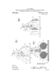
- Figure l is a side elevation of the machine embodied in my invention
- Fig. 2 is a similar view of the opposite side thereof
- Fig. 3 is a vertical longitudinal sectional view through the machine
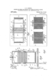
- Fig. l is va vertical transverse sectional View
- Fig. 5 is a horizontal sectional View taken in a plane with the bearings for the expressing roller oi the machine
- Fig. 6 is a similar View but taken below the bearings of the ribbon rolls or spools.
- the machine comprises a. base 10 which may be of wood or of metal as may he desired and sides 11 which extend vertically from the base in spaced parallel relation and adjacent, the side or longitudinal edge of the said base,
- the ribbon spools of the machine are indicated by the numeral 13 and thesespools are journaled' by means of suitable trunnions 14 which they carry at their sides, between the sides 11 t6 each side of the transverse middle of the machine.
- These spools may be of any desired size, both as regards width and diameter and may include any desired or conventional means for the attachment of the ends of the ribbon to be inked, thereto.
- the'sides 11 of the frame of the machine are cut away to form openings 15 through either of which a semi-cylindrical ink container 16 may be inserted into position between the said sides, the container being formed upon each of its sides with a pair of pins or studs 16 which project laterally.
- the studs 16 iipon'one side 'of the ink con-- tainer are inserted in openings 17' formed in one side 11 of the frame of the machine and the pins 16 at the other side of the container are positioned against the under edge of the opening 15 in the other side of the frame, one to each side of a projection 18 formed at the said edge of the opening and pivoted latch books 19, carried by the said side of the frame, are engaged with these last mentioned pins and serve to support the corresponding sides of the ink container.
- a vertically extending slot 20 is formed in each side 11 of the frame of the machine in a plane mid-way between the peripheries of the ribbon spools 13 and seated in each of these slots andresting at the lower end thereof, is a bearing block 21, the said blocks being formed at their side edges with flanges 22, the side edges of the slots being received between the flanges at the side edges of the corresponding blocks 21, the blocks being held in this manner-against :urcidcntal disengagement or displacement from the slots.
- An inking roller 23 is formed at itsends with trunnion 24 which are journalcdiu the bearing blocks 21 and thisrollcr is located partly within the ink container 16 so as to gather ink therefrom and apply it to the ribbon to be inked as ⁇ 'i ll be presently made apparent, the ribbon being wound upon one of the rollers 13 from the other roller, passing over the said inking roller 23.
- Bearing b ocks which eraser siniila construction to the blocks 21 exce tthat they are of greater height, are also mounted in the slots in the sides of the frame of the machine and journaled in these last mentioned.
- bearing bearing blocks are trunnions '26 at the ends oi an expressing roller 27, the said expressing, roller 27 being journaled in this manner directly above the inking roller 23 and the ribbon to be inked, which is indicated by the reference character 3, being passed as stated, over the inking roller 23 and between this roller and the expressing roller 27.
- bearing blocks 25 are slida-ble vertically in the slots 20.
- An adjusting screw 28 is threaded through a threaded opening 29 ned at the middle of the cross pieee 12 l nine of the machine and the lower nd of this adjusting screw is swiveled to a 3 spring 3 midway of the ends of the the leaf spring having its end bearing- 1 1; the upper ends of the block 25.
- the tendency of this spring 30 is, or" course, to
- the s rin serves to. 2') 3 hold the expressing roller 27 with a greater or less degree of firmness. against the inking roller 23 or, when the machine is in operation. against the ribbon which is trained. over th" roller 23.. the surplus ink taken up by the ribbon from the inking roller 23, being expre red and in this manner removed by the expressing roller 27, it being understood that the tension of the spring 30 may be adjusted by adjusting the screw 28 and consequently the ex 'n'essing roller may be llllllli ⁇ to bear with greater or' less pressure upon the roller 23, the amount of ink taken up and absorbed by the ribbon being in this manner regulated.
- the expressing roller may be brought to bear with a greater or, less degree oi ill'lilllOSS against the inking roller and that consequently the machine may be adapted to apply a greater or less quantity of ink to the ribbon to be treated.
- the ribbon nbsoi'biu loss ink as the expressing roller is brought [0 bear with considerable firmness against the inking roller.
- rollers may be made of metal with a wooden shell or sleeve or may be made of metal or wood with arubber or guttapercha covering or they may be made of wood or metal and provided with an absorbent covering of any desired material.
Landscapes
- Impression-Transfer Materials And Handling Thereof (AREA)
Description
v 1). N.:LENN0X. MACHINE FOR INKING AND REINKING TYPE WRITER AND SIMILAR RIBBONS.
APPLIOATION FILED MAR.27, 1908. RENEWED MAY 12, 19 10.
Patbnted Dec. 6, 1910.
9. BHEETSBHEET 1.
Damn/52272,
attain, 5
Patented Dec. 6, 1910.
2 SHEETS-SHEET Z D. N. LENNOX.
MACHINE FOR INKING AND REINKING TYPE WRITER AND SIMILAR RIBBONS.
APPLICATION FILEDMAB..27, 190a. RENEWED MAY 12, 1910. 977,661
ire s'rrin DAVID N. LENNOX, F GREENOCK, SCOTLAND.
Specification of Letters Patent.
Patented Dec. 6, 1815 Application filed. March 27, 1908, Serial E0. 423,755. Renewed May 12, 1910. Serial No. 560,981.
To all whom it may concern:
Be it known that I, DAVID NEIL LnNNoX, a sub ect'ot' the King of Great Britain, re-
siding at Greenock, Scotland, have invented certain new and useful Improvements in hiachines for Inking and R-einking Type- 1V riter and Similar Ribbons; and I do hereby declare the following to be a full, clear, and exact description of the invention, such as will enable others skilled in the art to which it appertains to make and use the same.
This invention relates to a machine designed for use-in inking and reinking typewriter and similar ribbons= In carrying out my invention, I have in view the provision of an extremely simple construction of machine for this purpose and one which may be used by any one for the purposeof reinking typewriter ribbons at a much lower cost than would be involved in the purchase of a new ribbon.
More specifically, the novelty in my invention resides in the provisionoi an expressing roller which coijperates with the inking roller of the machine to express surplus ink from the ribbon being treated and in the novel means devised by me for so adjusting this expressing roller that it will hear more or less firmly in the direction of the inking roller, this construction permitting of the ribbon being supplied with just the proper amount of ink.
Another novel feature of the invention resides in the manner of mounting the ink well or container, in which the inking roller is partly rotatable, so that it may be readily removed when it is desired to clean it or replenish it with ink.
In the accompanyi11gdrawings, Figure l is a side elevation of the machine embodied in my invention, Fig. 2 is a similar view of the opposite side thereof, Fig. 3 is a vertical longitudinal sectional view through the machine, Fig, l is va vertical transverse sectional View, Fig. 5 is a horizontal sectional View taken in a plane with the bearings for the expressing roller oi the machine; and, Fig. 6 is a similar View but taken below the bearings of the ribbon rolls or spools.
As shown in the drawings, the machine comprises a. base 10 which may be of wood or of metal as may he desired and sides 11 which extend vertically from the base in spaced parallel relation and adjacent, the side or longitudinal edge of the said base,
the said sides being connected at their up per ends by means of a cross piece 12 which may be integral with the said ends of the sides or separate therefrom and secured thereto. The ribbon spools of the machine are indicated by the numeral 13 and thesespools are journaled' by means of suitable trunnions 14 which they carry at their sides, between the sides 11 t6 each side of the transverse middle of the machine. These spools may be of any desired size, both as regards width and diameter and may include any desired or conventional means for the attachment of the ends of the ribbon to be inked, thereto. Between these spools l3, the'sides 11 of the frame of the machine are cut away to form openings 15 through either of which a semi-cylindrical ink container 16 may be inserted into position between the said sides, the container being formed upon each of its sides with a pair of pins or studs 16 which project laterally.
The studs 16 iipon'one side 'of the ink con-- tainer are inserted in openings 17' formed in one side 11 of the frame of the machine and the pins 16 at the other side of the container are positioned against the under edge of the opening 15 in the other side of the frame, one to each side of a projection 18 formed at the said edge of the opening and pivoted latch books 19, carried by the said side of the frame, are engaged with these last mentioned pins and serve to support the corresponding sides of the ink container.
A vertically extending slot 20 is formed in each side 11 of the frame of the machine in a plane mid-way between the peripheries of the ribbon spools 13 and seated in each of these slots andresting at the lower end thereof, is a bearing block 21, the said blocks being formed at their side edges with flanges 22, the side edges of the slots being received between the flanges at the side edges of the corresponding blocks 21, the blocks being held in this manner-against :urcidcntal disengagement or displacement from the slots. An inking roller 23 is formed at itsends with trunnion 24 which are journalcdiu the bearing blocks 21 and thisrollcr is located partly within the ink container 16 so as to gather ink therefrom and apply it to the ribbon to be inked as \\'i ll be presently made apparent, the ribbon being wound upon one of the rollers 13 from the other roller, passing over the said inking roller 23. Bearing b ocks which eraser siniila construction to the blocks 21 exce tthat they are of greater height, are also mounted in the slots in the sides of the frame of the machine and journaled in these last mentioned. bearing" blocks are trunnions '26 at the ends oi an expressing roller 27, the said expressing, roller 27 being journaled in this manner directly above the inking roller 23 and the ribbon to be inked, which is indicated by the reference character 3, being passed as stated, over the inking roller 23 and between this roller and the expressing roller 27.
It will be understood of course that the bearing blocks 25 are slida-ble vertically in the slots 20. An adjusting screw 28 is threaded through a threaded opening 29 ned at the middle of the cross pieee 12 l nine of the machine and the lower nd of this adjusting screw is swiveled to a 3 spring 3 midway of the ends of the the leaf spring having its end bearing- 1 1; the upper ends of the block 25. The tendency of this spring 30 is, or" course, to
c bearings in a downward direction and in doin this the s rin serves to. 2') 3 hold the expressing roller 27 with a greater or less degree of firmness. against the inking roller 23 or, when the machine is in operation. against the ribbon which is trained. over th" roller 23.. the surplus ink taken up by the ribbon from the inking roller 23, being expre red and in this manner removed by the expressing roller 27, it being understood that the tension of the spring 30 may be adjusted by adjusting the screw 28 and consequently the ex 'n'essing roller may be llllllli} to bear with greater or' less pressure upon the roller 23, the amount of ink taken up and absorbed by the ribbon being in this manner regulated.
l' ixcd upon on of the trunnions l-l for czich oi the ribbon spools a balanced handle fit. these handles serving as a means \vbcreb spools may be rotatcd to unwind the ribbon from one spool and wind it upon the oth r spool. i lar handle 32 is fixed to onc'ol thrtr .WHMIS 2U tor the expressing roller 3? and i handle is used under eondliioiis \i'bu-h will be presently explained. loaf spri .g 232' is lixcd to the inner face of each of ill{ sides ll of the frame of the 1111! cbinc adjacent cacb end thereof and these springs are bent 'to extend outwardly and to bear against tl adjacent cnd faces of the rozzalablc ribbon spools 123, the spring acting to prevent racing of the spools or in other words to llli'lli their freedoi'n of movement so tbal one s ion-l will not unwind a surplus of ri hon bile. the other spool is performing the windin operation.
'iho operation of the machine embodied in in ini'ention is as follows:-The ribbon to be inlnd first wound upon one of the spools i3 and the free .end of the ribbon is then inserted between the inking roller and the expressing roller, the handle for the expressing roller being then. rotated so as to receive the ribbon between the two rollers, I the ribbon being thencoiniected at its said end to the other spool 13 and the last men tioned spool, rotated to wind the ribbon thereon and to unwind it from the first mentioned spool 13. it will be understood in connection with the above description and from the d innings that the expressing roller may be brought to bear with a greater or, less degree oi ill'lilllOSS against the inking roller and that consequently the machine may be adapted to applya greater or less quantity of ink to the ribbon to be treated. the ribbon nbsoi'biu loss ink as the expressing roller is brought [0 bear with considerable firmness against the inking roller. a
It will be understood that l. am not to be limited to the particular material in manufacturing any of l e elements of the machine and particularly the inking and expressing rollers. These rollers may be made of metal with a wooden shell or sleeve or may be made of metal or wood with arubber or guttapercha covering or they may be made of wood or metal and provided with an absorbent covering of any desired material.
\Vhat claimed. is:
l. A machine of the class described com prising a frame including sides, rotatable ribbon spools mounted in the frame, an inking roller journaied in the frame, an expressing roller mounted in the frame in operative relation with respect to the ink ng roller, one of the sides ol the llillit being formed with openings latches fixed at the other side of the frame. an ink conlairer within which the inking roll r partly rotatable. and pins projecting lateral! from cach side of the ink container. pins at one side of the ink 0011-. taiucr being inserted in the openings in the said side of the frame, and-the pins at the other side of the ink container being engaged b the latches. Y
in a device of the hind described a pair of standards. an inking roll re'volubly supported in said standards, bearings slidably mount d in said standards, an expressing rbll revolublv supporlci'l in said bearings, a cross bar connecting said standards, a tension screw held in said cross bar and provided at its lower cud with a ball projection, and a lea t spring bcaring at its ends on the expressingroll bearings and connected to said spring by a socket arranged to form in conncction with the bail of the tension screw 21 ball and socket joint.
in testimony whereof. l', atiix my signaturc. in presence of two witnesses.
DAVID N. LENNOX. \Vitnesscs:
Ammli. imwroan, Puma iii. biir'rii.
Priority Applications (1)
| Application Number | Priority Date | Filing Date | Title |
|---|---|---|---|
| US56098110A US977661A (en) | 1910-05-12 | 1910-05-12 | Machine for inking and reinking type-writer and similar ribbons. |
Applications Claiming Priority (1)
| Application Number | Priority Date | Filing Date | Title |
|---|---|---|---|
| US56098110A US977661A (en) | 1910-05-12 | 1910-05-12 | Machine for inking and reinking type-writer and similar ribbons. |
Publications (1)
| Publication Number | Publication Date |
|---|---|
| US977661A true US977661A (en) | 1910-12-06 |
Family
ID=3046039
Family Applications (1)
| Application Number | Title | Priority Date | Filing Date |
|---|---|---|---|
| US56098110A Expired - Lifetime US977661A (en) | 1910-05-12 | 1910-05-12 | Machine for inking and reinking type-writer and similar ribbons. |
Country Status (1)
| Country | Link |
|---|---|
| US (1) | US977661A (en) |
Cited By (1)
| Publication number | Priority date | Publication date | Assignee | Title |
|---|---|---|---|---|
| US2747542A (en) * | 1953-11-06 | 1956-05-29 | Aloysius A Nowicki | Ribbon and roll inker for cash registers and like machines |
-
1910
- 1910-05-12 US US56098110A patent/US977661A/en not_active Expired - Lifetime
Cited By (1)
| Publication number | Priority date | Publication date | Assignee | Title |
|---|---|---|---|---|
| US2747542A (en) * | 1953-11-06 | 1956-05-29 | Aloysius A Nowicki | Ribbon and roll inker for cash registers and like machines |
Similar Documents
| Publication | Publication Date | Title |
|---|---|---|
| US3326124A (en) | System for re-filling printing ink containers of printing presses | |
| US341630A (en) | Ribbon-inking attachment for type-writing machines | |
| US624020A (en) | Nopris peters co | |
| US903672A (en) | Wall-papering machine. | |
| US2771028A (en) | Tape dispensing and printing device | |
| US427649A (en) | Printing attachment for paper-roll holders | |
| US530304A (en) | Whitney | |
| US1211341A (en) | Inking device. | |
| US1311688A (en) | Paper feeding device | |
| US848400A (en) | Sheet-winder. | |
| US831744A (en) | Paper-marking apparatus. | |
| US674966A (en) | Type-writing machine. | |
| US747325A (en) | Combined hand and automatic roll printing device. | |
| US656131A (en) | Advertising device. | |
| US441660A (en) | Printing attachment for paper-roll holders | |
| US1174704A (en) | Self-inking hand-stamp. | |
| US416821A (en) | Paper-reel with printing attachment | |
| US627355A (en) | Display device for photographs | |
| US1847526A (en) | Typewriting machine | |
| US1332632A (en) | Protective check-writing attachment fob | |
| US1596420A (en) | Drop platen | |
| US809188A (en) | Tag-stamping device. | |
| US519343A (en) | Paper-roll holder | |
| US976062A (en) | Device for recording or registering messages, memoranda, and the like. | |
| US1158519A (en) | Roll-holder for calculators. |