US9776294B2 - Apparatus for keeping a friction roller - Google Patents
Apparatus for keeping a friction roller Download PDFInfo
- Publication number
- US9776294B2 US9776294B2 US14/744,239 US201514744239A US9776294B2 US 9776294 B2 US9776294 B2 US 9776294B2 US 201514744239 A US201514744239 A US 201514744239A US 9776294 B2 US9776294 B2 US 9776294B2
- Authority
- US
- United States
- Prior art keywords
- friction roller
- cylinder
- pick
- brackets
- friction
- Prior art date
- Legal status (The legal status is an assumption and is not a legal conclusion. Google has not performed a legal analysis and makes no representation as to the accuracy of the status listed.)
- Expired - Fee Related, expires
Links
Images


Classifications
-
- B—PERFORMING OPERATIONS; TRANSPORTING
- B23—MACHINE TOOLS; METAL-WORKING NOT OTHERWISE PROVIDED FOR
- B23Q—DETAILS, COMPONENTS, OR ACCESSORIES FOR MACHINE TOOLS, e.g. ARRANGEMENTS FOR COPYING OR CONTROLLING; MACHINE TOOLS IN GENERAL CHARACTERISED BY THE CONSTRUCTION OF PARTICULAR DETAILS OR COMPONENTS; COMBINATIONS OR ASSOCIATIONS OF METAL-WORKING MACHINES, NOT DIRECTED TO A PARTICULAR RESULT
- B23Q3/00—Devices holding, supporting, or positioning work or tools, of a kind normally removable from the machine
- B23Q3/155—Arrangements for automatic insertion or removal of tools, e.g. combined with manual handling
- B23Q3/157—Arrangements for automatic insertion or removal of tools, e.g. combined with manual handling of rotary tools
- B23Q3/15713—Arrangements for automatic insertion or removal of tools, e.g. combined with manual handling of rotary tools a transfer device taking a single tool from a storage device and inserting it in a spindle
- B23Q3/1572—Arrangements for automatic insertion or removal of tools, e.g. combined with manual handling of rotary tools a transfer device taking a single tool from a storage device and inserting it in a spindle the storage device comprising rotating or circulating storing means
-
- A—HUMAN NECESSITIES
- A47—FURNITURE; DOMESTIC ARTICLES OR APPLIANCES; COFFEE MILLS; SPICE MILLS; SUCTION CLEANERS IN GENERAL
- A47B—TABLES; DESKS; OFFICE FURNITURE; CABINETS; DRAWERS; GENERAL DETAILS OF FURNITURE
- A47B49/00—Revolving cabinets or racks; Cabinets or racks with revolving parts
- A47B49/008—Revolving cabinets or racks; Cabinets or racks with revolving parts with motorisation means
-
- B—PERFORMING OPERATIONS; TRANSPORTING
- B65—CONVEYING; PACKING; STORING; HANDLING THIN OR FILAMENTARY MATERIAL
- B65G—TRANSPORT OR STORAGE DEVICES, e.g. CONVEYORS FOR LOADING OR TIPPING, SHOP CONVEYOR SYSTEMS OR PNEUMATIC TUBE CONVEYORS
- B65G1/00—Storing articles, individually or in orderly arrangement, in warehouses or magazines
- B65G1/02—Storage devices
-
- G—PHYSICS
- G02—OPTICS
- G02F—OPTICAL DEVICES OR ARRANGEMENTS FOR THE CONTROL OF LIGHT BY MODIFICATION OF THE OPTICAL PROPERTIES OF THE MEDIA OF THE ELEMENTS INVOLVED THEREIN; NON-LINEAR OPTICS; FREQUENCY-CHANGING OF LIGHT; OPTICAL LOGIC ELEMENTS; OPTICAL ANALOGUE/DIGITAL CONVERTERS
- G02F1/00—Devices or arrangements for the control of the intensity, colour, phase, polarisation or direction of light arriving from an independent light source, e.g. switching, gating or modulating; Non-linear optics
- G02F1/01—Devices or arrangements for the control of the intensity, colour, phase, polarisation or direction of light arriving from an independent light source, e.g. switching, gating or modulating; Non-linear optics for the control of the intensity, phase, polarisation or colour
- G02F1/13—Devices or arrangements for the control of the intensity, colour, phase, polarisation or direction of light arriving from an independent light source, e.g. switching, gating or modulating; Non-linear optics for the control of the intensity, phase, polarisation or colour based on liquid crystals, e.g. single liquid crystal display cells
- G02F1/1303—Apparatus specially adapted to the manufacture of LCDs
-
- B—PERFORMING OPERATIONS; TRANSPORTING
- B23—MACHINE TOOLS; METAL-WORKING NOT OTHERWISE PROVIDED FOR
- B23Q—DETAILS, COMPONENTS, OR ACCESSORIES FOR MACHINE TOOLS, e.g. ARRANGEMENTS FOR COPYING OR CONTROLLING; MACHINE TOOLS IN GENERAL CHARACTERISED BY THE CONSTRUCTION OF PARTICULAR DETAILS OR COMPONENTS; COMBINATIONS OR ASSOCIATIONS OF METAL-WORKING MACHINES, NOT DIRECTED TO A PARTICULAR RESULT
- B23Q3/00—Devices holding, supporting, or positioning work or tools, of a kind normally removable from the machine
- B23Q3/155—Arrangements for automatic insertion or removal of tools, e.g. combined with manual handling
- B23Q3/1552—Arrangements for automatic insertion or removal of tools, e.g. combined with manual handling parts of devices for automatically inserting or removing tools
- B23Q3/15546—Devices for recognizing tools in a storage device, e.g. coding devices
-
- Y—GENERAL TAGGING OF NEW TECHNOLOGICAL DEVELOPMENTS; GENERAL TAGGING OF CROSS-SECTIONAL TECHNOLOGIES SPANNING OVER SEVERAL SECTIONS OF THE IPC; TECHNICAL SUBJECTS COVERED BY FORMER USPC CROSS-REFERENCE ART COLLECTIONS [XRACs] AND DIGESTS
- Y10—TECHNICAL SUBJECTS COVERED BY FORMER USPC
- Y10T—TECHNICAL SUBJECTS COVERED BY FORMER US CLASSIFICATION
- Y10T483/00—Tool changing
- Y10T483/10—Process
-
- Y—GENERAL TAGGING OF NEW TECHNOLOGICAL DEVELOPMENTS; GENERAL TAGGING OF CROSS-SECTIONAL TECHNOLOGIES SPANNING OVER SEVERAL SECTIONS OF THE IPC; TECHNICAL SUBJECTS COVERED BY FORMER USPC CROSS-REFERENCE ART COLLECTIONS [XRACs] AND DIGESTS
- Y10—TECHNICAL SUBJECTS COVERED BY FORMER USPC
- Y10T—TECHNICAL SUBJECTS COVERED BY FORMER US CLASSIFICATION
- Y10T483/00—Tool changing
- Y10T483/13—Tool changing with control means energized in response to activator stimulated by condition sensor
-
- Y—GENERAL TAGGING OF NEW TECHNOLOGICAL DEVELOPMENTS; GENERAL TAGGING OF CROSS-SECTIONAL TECHNOLOGIES SPANNING OVER SEVERAL SECTIONS OF THE IPC; TECHNICAL SUBJECTS COVERED BY FORMER USPC CROSS-REFERENCE ART COLLECTIONS [XRACs] AND DIGESTS
- Y10—TECHNICAL SUBJECTS COVERED BY FORMER USPC
- Y10T—TECHNICAL SUBJECTS COVERED BY FORMER US CLASSIFICATION
- Y10T483/00—Tool changing
- Y10T483/17—Tool changing including machine tool or component
- Y10T483/1733—Rotary spindle machine tool [e.g., milling machine, boring, machine, grinding machine, etc.]
- Y10T483/1748—Tool changer between spindle and matrix
- Y10T483/1783—Tool changer between spindle and matrix including linearly translatable tool changer [e.g., shuttle, ram, etc.]
- Y10T483/1786—Plural tool holders
-
- Y—GENERAL TAGGING OF NEW TECHNOLOGICAL DEVELOPMENTS; GENERAL TAGGING OF CROSS-SECTIONAL TECHNOLOGIES SPANNING OVER SEVERAL SECTIONS OF THE IPC; TECHNICAL SUBJECTS COVERED BY FORMER USPC CROSS-REFERENCE ART COLLECTIONS [XRACs] AND DIGESTS
- Y10—TECHNICAL SUBJECTS COVERED BY FORMER USPC
- Y10T—TECHNICAL SUBJECTS COVERED BY FORMER US CLASSIFICATION
- Y10T483/00—Tool changing
- Y10T483/18—Tool transfer to or from matrix
- Y10T483/1873—Indexing matrix
Definitions
- the disclosure relates to the field of liquid crystal manufacturing device storage, and in particular, to an apparatus for keeping a friction roller.
- the friction process refers to rubbing a glass substrate by a friction roller, to cause an alignment film on the glass substrate to have the ability of aligning liquid crystal molecules, such that the liquid crystal molecules have a desired inclination angle.
- the quality of a friction roller is crucial to the product quality.
- On the surface of the friction roller is glued a layer of cloth with a double-sided adhesive, which is called friction cloth.
- friction cloth On the surface of the friction roller is glued a layer of cloth with a double-sided adhesive, which is called friction cloth.
- each piece of friction cloth has a lifetime, and therefore the storage of the friction roller is a relatively complicated task.
- FIG. 1 shows a schematic diagram of a structure for storing a friction roller in the prior art.
- a way of storing a friction roller in the prior art is that a pre-stored friction roller is placed in a friction roller feeding area 13 , a plurality of brackets 2 are fixed at a position to the side of a store, and a friction roller pick-and-place execution mechanism 14 is disposed in the middle of the store, and picks and places a friction roller from the plurality of brackets 2 .
- the disclosure provides an apparatus for keeping a friction roller to solve the problems of a limited storage quantity and a low work efficiency existing in the structure for storing a friction roller in the prior art.
- the apparatus for keeping a friction roller comprises: a cylinder provided with a plurality of brackets for storing the friction roller, a friction roller pick-and-place execution unit for picking and placing the friction roller, a cylinder driving unit for driving the cylinder to rotate, a storage sensor unit for sensing whether a friction roller exists on a bracket, a pick-and-place position sensor unit for sensing whether a bracket arrives at a pick-and-place position of the friction roller, and a control unit, wherein the friction roller pick-and-place execution unit is disposed at a position close to the cylinder; the cylinder comprises a fixed part and a rotating part, the rotating part is connected with the cylinder driving unit, the plurality of brackets are juxtaposed at the periphery of the rotating part of the cylinder, the storage sensor unit is disposed on the fixed part of the cylinder and corresponds to a position storing the friction roller on a bracket, and the pick-and-place position sensor unit is disposed at a position on the fixed part of the
- the apparatus for keeping a friction roller further comprises an origin position sensor unit disposed at a position on the fixed part of the cylinder close to the friction roller pick-and-place execution unit, which position is called the cylinder origin position.
- the fixed part of the cylinder comprises two placement platforms disposed at both ends of the rotating part of the cylinder.
- the storage sensor unit comprises a plurality of pairs of first sensors uniformly distributed on the placement platforms, and individual pairs of first sensors are oppositely placed on the two placement platforms at both ends of the rotating part of the cylinder respectively.
- the pick-and-place position sensor unit comprises a pair of second sensors disposed at the periphery of the placement platforms, and the pair of second sensors is oppositely placed on the two placement platforms at both ends of the rotating part of the cylinder respectively.
- the origin position sensor unit comprises a pair of third sensors disposed at the periphery of the placement platforms, and the pair of third sensors is oppositely placed on the two placement platforms at both ends of the rotating part of the cylinder respectively.
- the brackets have a first through-hole for use with the pair of second sensors and a second through-hole for use with the pair of third sensors.
- the brackets are disposed at an acute angle with respect to the axis of the cylinder, such that the rotation is more stationary.
- the cylinder driving unit comprises a driving motor and a transmission belt, wherein the rotating part of the cylinder is connected with the driving motor via the transmission belt, such that the driving motor drives the rotating part of the cylinder to rotate through the transmission belt.
- the apparatus for keeping a friction roller there are further comprised a store and a traveling track disposed in the middle of the store, wherein the friction roller pick-and-place execution unit is disposed on the traveling track and a plurality of the cylinders are disposed around the traveling track.
- a bar code scanner which is connected with the control unit.
- a method for depositing a friction roller in an apparatus for keeping a friction roller which comprises the following steps of:
- the bar code scanner reading the bar code on the friction roller and transmitting the information to the control unit;
- control unit controlling the cylinder driving unit to drive the rotating part of the cylinder according to the information on the positions of the pre-placing brackets, and causing the pre-placing brackets to rotate to a pick-and-place position by means of the pick-and-place position sensor unit, and the friction roller pick-and-place execution unit taking out the friction roller from the friction roller feeding area and placing on a corresponding bracket in the cylinder;
- control unit controlling the cylinder driving unit to drive the brackets, and causing the specified bracket to rotate back to the cylinder origin position by means of the origin position sensor unit.
- a method for taking out a friction roller in an apparatus for keeping a friction roller which comprises the following steps of:
- control unit controlling the cylinder driving unit to drive the rotating part of the cylinder and causing a bracket where a friction roller corresponding to the bar code is located to rotate to a pick-and-place position by means of the pick-and-place position sensor unit;
- the friction roller pick-and-place execution unit taking down the friction roller on the corresponding bracket and placing it in the friction roller feeding area, and the bar code scanner reading the bar code on the friction roller to confirm its identity;
- control unit controlling the cylinder driving unit to drive the brackets, and causing the specified bracket to rotate back to the cylinder origin position by means of the origin position sensor unit.
- a plurality of brackets are juxtaposed at the periphery of the rotating part of the cylinder for storing the friction roller
- the storage sensor unit and the pick-and-place position sensor unit are disposed on the fixed part of the cylinder and thus may respectively ascertain whether a friction roller exists on the brackets and whether a bracket where the friction roller is located arrives at a pick-and-place position and pass such information to the control unit, and in turn, the friction roller pick-and-place execution unit accesses the friction roller under the control of the control unit, such that more friction rollers may be accessed accurately, and the number of the stored friction rollers is increased very greatly; and since the friction roller pick-and-place execution unit is disposed at a position close to the cylinder, the stroke of its pick-and-place action is relatively short, and thereby the work efficiency of picking and placing a friction roller is also increased very greatly.
- FIG. 1 is a schematic diagram of a structure for storing a friction roller in the prior art
- FIG. 2 is a schematic plan view of an apparatus for keeping a friction roller according to an embodiment of the disclosure
- FIG. 3 is a three-dimensional structural schematic diagram of the cylinder in the apparatus for keeping a friction roller according to an embodiment of the disclosure
- FIG. 4 is a schematic plan view of the cylinder in the apparatus for keeping a friction roller according to an embodiment of the disclosure
- FIG. 5 is a schematic plan view after a placement platform is removed at the top of the cylinder in the apparatus for keeping a friction roller according to an embodiment of the disclosure
- FIG. 6 is a schematic diagram of an arrangement of individual sensors on a placement platform in the apparatus for keeping a friction roller according to an embodiment of the disclosure
- FIG. 7 is a schematic plan view after a placement platform is removed at the bottom of the cylinder in the apparatus for keeping a friction roller according to an embodiment of the disclosure.
- FIG. 8 is a structural schematic side view of the cylinder driving unit at the bottom of the cylinder in the apparatus for keeping a friction roller according to an embodiment of the disclosure.
- 1 denotes cylinder; 2 bracket; 3 first sensor; 4 placement platform; 5 traveling track; 6 first through-hole; 7 second sensor; 8 cylinder origin position; 9 second through-hole; 10 third sensor; 11 driving motor; 12 transmission belt; 13 friction roller feeding area; 14 friction roller pick-and-place execution unit; 15 store.
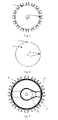
- FIG. 2 shows a schematic plan view of an apparatus for keeping a friction roller according to an embodiment of the disclosure.
- the apparatus for keeping a friction roller according to an embodiment of the disclosure comprises a cylinder 1 , a friction roller pick-and-place execution unit 14 , and besides, further comprises a control unit, a cylinder driving unit, a storage sensor unit and a pick-and-place position sensor unit not shown in the figure.
- a plurality of brackets 2 for storing a friction roller are disposed at the periphery of the cylinder 1 , and the friction roller pick-and-place execution unit 14 is disposed at a position close to the cylinder 1 for picking and placing a friction roller from/to a bracket 2 .
- the apparatus for keeping a friction roller may further comprise a store 15 and a traveling track 5 disposed in the middle of the store 15 , and a plurality of the cylinders 1 may be disposed around the traveling track 5 .
- the friction roller pick-and-place execution unit 14 may be disposed on the traveling track 5 and slide thereon, and thereby may be close to an individual cylinder 1 for accessing a friction roller.
- the end of the traveling track 5 close to the inlet of the store 15 is a friction roller feeding area 13 .
- a bar code scanner may be disposed, which is connected with the control unit.
- the bar code scanner may read information on a bar code stuck on a pre-stored friction roller and pass the information to the control unit, such that a storage position of the friction roller in the store 15 may be traced.
- FIG. 3 and FIG. 4 respectively show a three-dimensional structural schematic diagram and a schematic plan view of the cylinder in the apparatus for keeping a friction roller according to an embodiment of the disclosure.
- the cylinder 1 comprises a fixed part and a rotating part, wherein as shown in FIG. 3 and FIG. 4 , the rotating part may be the plurality of brackets 2 for storing a friction roller disposed at the periphery of the cylinder 1 , and is driven by the cylinder driving unit connected with it, whereas the fixed part is particularly two placement platforms 4 disposed at both ends of the rotating part of the cylinder 1 respectively.
- the storage sensor unit is disposed on the placement platforms 4 at both ends of the cylinder 1 and corresponds to a position on a bracket 2 storing a friction roller for sensing whether a friction roller exists on the bracket 2 ;
- the pick-and-place position sensor unit is disposed at a position on a placement platform 4 of the cylinder 1 close to the friction roller pick-and-place execution unit 14 as shown in FIG.
- a friction roller pick-and-place position i.e., a position corresponding to the pick-and-place position sensor unit
- the friction roller pick-and-place execution unit 14 , the storage sensor unit, the pick-and-place position sensor unit and the cylinder driving unit are all connected with the control unit and uniformly controlled by the control unit.
- a plurality of friction rollers may be placed vertically on the plurality of brackets 2 respectively, and with the rotation of the cylinder 1 , the brackets 2 may bring the friction rollers to rotate.
- the storage sensor unit may sense whether a friction roller exists on a bracket 2 ;
- the pick-and-place position sensor unit may sense whether a bracket 2 where a friction roller predetermined to be accessed is located arrives at a friction roller pick-and-place position; and the control unit may control the friction roller pick-and-place execution unit 14 to perform the action of picking and placing a friction roller accordingly according to the information sensed by the two sensor units.
- the control unit may control the friction roller pick-and-place execution unit 14 to perform a corresponding action of storing a friction roller; while in the process of taking out a friction roller from the apparatus for keeping a friction roller, if the pick-and-place position sensor unit senses that a bracket 2 where a friction roller predetermined to be accessed is located arrives at a friction roller pick-and-place position and the storage sensor unit senses that a friction roller is deposited on the bracket 2 , the control unit may control the friction roller pick-and-place execution unit 14 to perform a corresponding action of taking out a friction roller.
- FIG. 6 shows a schematic diagram of an arrangement of individual sensor units on a placement platform 4 in the apparatus for keeping a friction roller according to an embodiment of the disclosure.
- the storage sensor unit comprises a plurality of pairs of first sensors 3 uniformly distributed on the placement platforms 4 , and individual pairs of first sensors 3 are oppositely placed on the two placement platforms 4 at both ends of the rotating part of the cylinder 1 respectively. Since a pair of first sensors 3 corresponds to a position storing a friction roller on a bracket 2 , the pair of first sensors 3 may sense whether a friction roller exists on the racket 2 between each other for example by the infrared shoot sensing technique and thereby pass the information to the control unit.
- the pick-and-place position sensor unit comprises a pair of second sensors 7 disposed at the periphery of the placement platforms 4 , which are oppositely placed on the two placement platforms 4 at both ends of the rotating part of the cylinder 1 respectively.
- the apparatus for keeping a friction roller may further comprise an origin position sensor unit which is disposed at a position on a placement platform 4 of the cylinder close to the friction roller pick-and-place execution unit 14 .
- the origin position sensor unit comprises a pair of third sensors 10 disposed at the periphery of the placement platforms 4 , and the pair of third sensors 10 is oppositely placed on the two placement platforms 4 at both ends of the rotating part of the cylinder 1 respectively, generally disposed near the second sensors 7 .
- the position where the origin position sensor unit e.g., the third sensor 10
- the cylinder origin position e.g., 8 as shown in FIG. 2 ).
- the relative positions of individual brackets 2 of the cylinder 1 may be determined, thereby facilitating the access of a friction roller on a certain bracket 2 .
- FIG. 5 and FIG. 7 respectively show a schematic plan view after a placement platform is removed at the top and the bottom of the cylinder in the apparatus for keeping a friction roller according to an embodiment of the disclosure.
- each bracket 2 has a first through-hole 6 for the pair of second sensors 7 to sense whether the bracket 2 is at a pick-and-place position for example by the infrared shoot sensing technique; and a specified bracket 2 has a second through-hole 9 for the pair of third sensors 10 to sense whether the specified bracket 2 is at the cylinder origin position for example by the infrared shoot sensing technique.
- the pair of second sensors 7 shoots via a corresponding first through-hole 6 of a bracket 2 , indicating that a corresponding bracket 2 arrives at a pick-and-place position, they will transmit information that a corresponding bracket 2 arrives at a pick-and-place position; and for example when the pair of third sensors 10 shoots via a corresponding second through-hole 9 , they will transmit information that the specified bracket 2 arrives at the cylinder origin position.
- the position where the whole brackets 2 (or the rotating part of the cylinder 1 ) are located when the specified bracket 2 is at the cylinder origin position may be set to be an initial position, and at this point, the relative positions of all the brackets 2 may be determined, and the relative positions may be taken as the position information of the brackets 2 in the following.
- brackets 2 may be disposed at an acute angle with respect to the axis of the cylinder 1 , for example, the angle may be 5°.
- the angle may be 5°.
- FIG. 8 is a structural schematic side view of the cylinder driving unit at the bottom of the cylinder in the apparatus for keeping a friction roller according to an embodiment of the disclosure.
- the cylinder driving unit comprises a driving motor 11 and a transmission belt 12 , and the rotating part of the cylinder 1 is connected with the driving motor 11 via the transmission belt 12 .
- the driving motor 11 is connected with the control unit. Under the driving of the driving motor 11 , the rotating part of the cylinder 1 is brought to rotate via the transmission belt 12 .
- a method for depositing a friction roller may comprise the following steps:
- control unit controlling the cylinder driving unit to drive the rotating part of the cylinder 1 according to the information on the positions of the pre-placing brackets 2 , and causing the pre-placing brackets 2 to rotate to a pick-and-place position by means of the pick-and-place position sensor unit (i.e., the second sensors), and the friction roller pick-and-place execution unit 14 taking out the friction roller from the friction roller feeding area 13 and placing on a corresponding bracket 2 in the cylinder 1 ; and
- the control unit controlling the cylinder driving unit to drive the brackets 2 , and causing the specified bracket 2 to rotate back to the cylinder origin position 8 by means of the origin position sensor unit (i.e., the third sensors), i.e., the whole brackets 2 restore to the initial position.
- the origin position sensor unit i.e., the third sensors
- a method for taking out a friction roller may comprise the following steps:
- control unit controlling the cylinder driving unit to drive the rotating part of the cylinder 1 and causing a bracket 2 where a friction roller corresponding to the bar code is located to rotate to a pick-and-place position by means of the pick-and-place position sensor unit;
- the control unit controlling the cylinder driving unit to drive the brackets 2 , and causing the specified bracket 2 to rotate back to the cylinder origin position 8 by means of the origin position sensor unit (i.e., the third sensors), i.e., the whole brackets 2 restore to the initial position.
- the origin position sensor unit i.e., the third sensors
- a plurality of brackets 2 are juxtaposed at the periphery of the rotating part of the cylinder 1 for storing the friction roller
- the storage sensor unit and the pick-and-place position sensor unit are disposed on the placement platforms 4 at both ends of the cylinder 1 and thus may respectively sense whether a friction roller exists on the brackets 2 and whether a bracket 2 where the friction roller is located arrives at a pick-and-place position, and in turn, the friction roller pick-and-place execution unit 14 may be controlled to access the friction roller under the control of the control unit, such that more friction rollers may be accessed accurately, and the number of the stored friction rollers is increased very greatly.
- the friction roller pick-and-place execution unit 14 is disposed at a position close to the cylinder 1 , the stroke of its action is relatively short, and thereby the work efficiency of picking and placing a friction roller is also increased very greatly. Additionally, since the capability of the store 15 of storing friction rollers is promoted, it is unnecessary to build a store once more, and thereby the production cost is also lowered.
Landscapes
- Physics & Mathematics (AREA)
- Engineering & Computer Science (AREA)
- Nonlinear Science (AREA)
- Mechanical Engineering (AREA)
- Manufacturing & Machinery (AREA)
- Chemical & Material Sciences (AREA)
- Crystallography & Structural Chemistry (AREA)
- General Physics & Mathematics (AREA)
- Optics & Photonics (AREA)
- Warehouses Or Storage Devices (AREA)
- Robotics (AREA)
- Rollers For Roller Conveyors For Transfer (AREA)
Abstract
Description
Claims (12)
Applications Claiming Priority (3)
| Application Number | Priority Date | Filing Date | Title |
|---|---|---|---|
| CN201410686540.X | 2014-11-24 | ||
| CN201410686540.XA CN104495189B (en) | 2014-11-24 | 2014-11-24 | A kind of friction roller storage appts |
| CN201410686540 | 2014-11-24 |
Publications (2)
| Publication Number | Publication Date |
|---|---|
| US20160143436A1 US20160143436A1 (en) | 2016-05-26 |
| US9776294B2 true US9776294B2 (en) | 2017-10-03 |
Family
ID=52936672
Family Applications (1)
| Application Number | Title | Priority Date | Filing Date |
|---|---|---|---|
| US14/744,239 Expired - Fee Related US9776294B2 (en) | 2014-11-24 | 2015-06-19 | Apparatus for keeping a friction roller |
Country Status (2)
| Country | Link |
|---|---|
| US (1) | US9776294B2 (en) |
| CN (1) | CN104495189B (en) |
Families Citing this family (1)
| Publication number | Priority date | Publication date | Assignee | Title |
|---|---|---|---|---|
| CN111134460A (en) * | 2020-02-20 | 2020-05-12 | 埃尔法帝智能科技(上海)有限公司 | A Controllable Fractional Format Disc |
Citations (12)
| Publication number | Priority date | Publication date | Assignee | Title |
|---|---|---|---|---|
| US3187123A (en) * | 1961-04-03 | 1965-06-01 | Scully Anthony Corp | Binary key identifier for machine tools |
| US3657627A (en) * | 1969-07-23 | 1972-04-18 | Fujitsu Ltd | Tool selection system |
| DE2609337A1 (en) * | 1976-03-06 | 1977-09-08 | Kelch & Co Werkzeugmaschf | Machine tool automatic tool exchange - has feeler probing each magazine tool position, and has tool issuing and return unit |
| US4109188A (en) * | 1976-11-06 | 1978-08-22 | Toyoda-Koki Kabushiki-Kaisha | Index device for tool storage magazine |
| JPS6244337A (en) * | 1985-08-22 | 1987-02-26 | Yamazaki Mazak Corp | Tool magazine |
| GB2199022A (en) | 1986-11-20 | 1988-06-29 | Shimizu Construction Co Ltd | Storing semi-conductor wafers in cassettes |
| US5065905A (en) | 1990-05-23 | 1991-11-19 | Xerox Corporation | Hardware delivery system |
| US5304110A (en) * | 1991-06-03 | 1994-04-19 | Erowa Ag | Magazine for tools and/or workpieces |
| US6024681A (en) * | 1996-10-18 | 2000-02-15 | Amada Gmbh | Tool changing mechanism for a metal forming press |
| TW561520B (en) | 2001-01-12 | 2003-11-11 | Asyst Technoligies Inc | Reticle management system |
| CN201942242U (en) | 2011-02-14 | 2011-08-24 | 四川迈克生物科技股份有限公司 | Sample storehouse for sample storage and transfer |
| CN203740596U (en) | 2014-03-25 | 2014-07-30 | 合肥鑫晟光电科技有限公司 | Friction roller taking-and-placing device |
-
2014
- 2014-11-24 CN CN201410686540.XA patent/CN104495189B/en not_active Expired - Fee Related
-
2015
- 2015-06-19 US US14/744,239 patent/US9776294B2/en not_active Expired - Fee Related
Patent Citations (12)
| Publication number | Priority date | Publication date | Assignee | Title |
|---|---|---|---|---|
| US3187123A (en) * | 1961-04-03 | 1965-06-01 | Scully Anthony Corp | Binary key identifier for machine tools |
| US3657627A (en) * | 1969-07-23 | 1972-04-18 | Fujitsu Ltd | Tool selection system |
| DE2609337A1 (en) * | 1976-03-06 | 1977-09-08 | Kelch & Co Werkzeugmaschf | Machine tool automatic tool exchange - has feeler probing each magazine tool position, and has tool issuing and return unit |
| US4109188A (en) * | 1976-11-06 | 1978-08-22 | Toyoda-Koki Kabushiki-Kaisha | Index device for tool storage magazine |
| JPS6244337A (en) * | 1985-08-22 | 1987-02-26 | Yamazaki Mazak Corp | Tool magazine |
| GB2199022A (en) | 1986-11-20 | 1988-06-29 | Shimizu Construction Co Ltd | Storing semi-conductor wafers in cassettes |
| US5065905A (en) | 1990-05-23 | 1991-11-19 | Xerox Corporation | Hardware delivery system |
| US5304110A (en) * | 1991-06-03 | 1994-04-19 | Erowa Ag | Magazine for tools and/or workpieces |
| US6024681A (en) * | 1996-10-18 | 2000-02-15 | Amada Gmbh | Tool changing mechanism for a metal forming press |
| TW561520B (en) | 2001-01-12 | 2003-11-11 | Asyst Technoligies Inc | Reticle management system |
| CN201942242U (en) | 2011-02-14 | 2011-08-24 | 四川迈克生物科技股份有限公司 | Sample storehouse for sample storage and transfer |
| CN203740596U (en) | 2014-03-25 | 2014-07-30 | 合肥鑫晟光电科技有限公司 | Friction roller taking-and-placing device |
Non-Patent Citations (1)
| Title |
|---|
| Office action from Chinese Application No. 201410686540.X dated Feb. 19, 2016. |
Also Published As
| Publication number | Publication date |
|---|---|
| CN104495189A (en) | 2015-04-08 |
| CN104495189B (en) | 2016-06-29 |
| US20160143436A1 (en) | 2016-05-26 |
Similar Documents
| Publication | Publication Date | Title |
|---|---|---|
| US9568753B2 (en) | Turnover device, substrate cell-assembling apparatus and substrate cell-assembling method | |
| US8864435B2 (en) | Turnover device of liquid crystal panel | |
| JP4705624B2 (en) | Substrate etching apparatus and liquid crystal display element production line using the same | |
| KR101190911B1 (en) | Method and apparatus for the contamination-free treatment of shock-sensitive glass plates in ultra clean rooms | |
| KR101400676B1 (en) | Apparatus for attaching film and method for attaching film using the same | |
| US20160272424A1 (en) | Fork assembly for storage/retrieval machine and storage/retrieval machine, method for conveying cartridges | |
| CN102183854A (en) | Panel alignment device and panel alignment method | |
| CN104802495B (en) | Panel sticker | |
| CN102275707A (en) | Panel holding rack and panel conveying system | |
| CN204287670U (en) | Polaroid visual-alignment device | |
| US9776294B2 (en) | Apparatus for keeping a friction roller | |
| KR100884585B1 (en) | Transfer system for substrate | |
| CN203037589U (en) | Line positive scanning video detection system | |
| CN103399431B (en) | A kind of liquid crystal display light orientation exposure device | |
| CN103935138B (en) | A kind of stamp system, method and device | |
| CN102759812A (en) | Automatic processing system applicable to LCD panel | |
| CN207781550U (en) | Substrate alignment detection apparatus | |
| US11084265B2 (en) | Manufacturing system for laminated film and manufacturing method for laminated film | |
| CN100462842C (en) | camera device | |
| US7881819B2 (en) | Substrate transfer apparatus, method of transferring substrate, and method of manufacturing electro-optical device | |
| US20130199896A1 (en) | Conveyor control apparatus of liquid crystal panel substrates and control method thereof | |
| CN204595585U (en) | A kind of novel automatic production line training device | |
| CN102252615B (en) | Stamped mark width measuring device and method | |
| CN103213369A (en) | Film laminating device | |
| CN208616924U (en) | A kind of glass positioning conveying whirler |
Legal Events
| Date | Code | Title | Description |
|---|---|---|---|
| AS | Assignment |
Owner name: BOE TECHNOLOGY GROUP CO., LTD., CHINA Free format text: ASSIGNMENT OF ASSIGNORS INTEREST;ASSIGNORS:LIU, LAIFENG;HUANG, ZHUBING;JING, HUI;AND OTHERS;REEL/FRAME:036216/0013 Effective date: 20150605 Owner name: HEFEI XINSHENG OPTOELECTRONICS TECHNOLOGY CO., LTD Free format text: ASSIGNMENT OF ASSIGNORS INTEREST;ASSIGNORS:LIU, LAIFENG;HUANG, ZHUBING;JING, HUI;AND OTHERS;REEL/FRAME:036216/0013 Effective date: 20150605 |
|
| STCF | Information on status: patent grant |
Free format text: PATENTED CASE |
|
| MAFP | Maintenance fee payment |
Free format text: PAYMENT OF MAINTENANCE FEE, 4TH YEAR, LARGE ENTITY (ORIGINAL EVENT CODE: M1551); ENTITY STATUS OF PATENT OWNER: LARGE ENTITY Year of fee payment: 4 |
|
| FEPP | Fee payment procedure |
Free format text: MAINTENANCE FEE REMINDER MAILED (ORIGINAL EVENT CODE: REM.); ENTITY STATUS OF PATENT OWNER: LARGE ENTITY |
|
| LAPS | Lapse for failure to pay maintenance fees |
Free format text: PATENT EXPIRED FOR FAILURE TO PAY MAINTENANCE FEES (ORIGINAL EVENT CODE: EXP.); ENTITY STATUS OF PATENT OWNER: LARGE ENTITY |
|
| STCH | Information on status: patent discontinuation |
Free format text: PATENT EXPIRED DUE TO NONPAYMENT OF MAINTENANCE FEES UNDER 37 CFR 1.362 |
|
| FP | Lapsed due to failure to pay maintenance fee |
Effective date: 20251003 |